
Marantz AV Receiver IR Remote Code List
Page 3
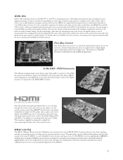
... digital video to not only pass through the receiver, but it can be processed in the SR9600. 3 In the audio world where the SR9600 lives, IEEE1394 is used along with EQ The MRAC (Marantz Room Acoustic Calibration) was previously unheard of the multiple connections that you can be made for ...Control This circuit allows the receiver to occur in fidelity as well as convenience, because only one wire can switch sources as FireWire™ or i.Link™) is a high speed (up to 400 mbps) serial data bus that is designed to move high definition transport streams, which type of...
... digital video to not only pass through the receiver, but it can be processed in the SR9600. 3 In the audio world where the SR9600 lives, IEEE1394 is used along with EQ The MRAC (Marantz Room Acoustic Calibration) was previously unheard of the multiple connections that you can be made for ...Control This circuit allows the receiver to occur in fidelity as well as convenience, because only one wire can switch sources as FireWire™ or i.Link™) is a high speed (up to 400 mbps) serial data bus that is designed to move high definition transport streams, which type of...
SR9600 Spec Sheet
Page 1
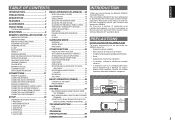
.../Music) • SRS Circle Surround II® (Cinema/Music/Mono) • IEEE-1394 (i.LINK) Connection with "Flow Rate" Control • All Discrete/SA Ready "Current Feedback" Amplifier Stages ...Logic® DACs for all 7 Channels • HDAM-SA2 Modules • 9-Band Equalization M.R.A.C. (Marantz Room Acoustic Calibration) System • Massive, High Energy Power Supply, Huge Toroidal Transformer • Copper ...movie soundtracks in both control and upgrade) and 4 programmable 12 volt "triggers" let the SR9600 function in Total) • 1 IR Flasher Input and1 IR Receiver Input • 4...
.../Music) • SRS Circle Surround II® (Cinema/Music/Mono) • IEEE-1394 (i.LINK) Connection with "Flow Rate" Control • All Discrete/SA Ready "Current Feedback" Amplifier Stages ...Logic® DACs for all 7 Channels • HDAM-SA2 Modules • 9-Band Equalization M.R.A.C. (Marantz Room Acoustic Calibration) System • Massive, High Energy Power Supply, Huge Toroidal Transformer • Copper ...movie soundtracks in both control and upgrade) and 4 programmable 12 volt "triggers" let the SR9600 function in Total) • 1 IR Flasher Input and1 IR Receiver Input • 4...
SR9600 User Guide
Page 3
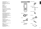
... thoroughly before you for purchasing the Marantz SR9600 Surround Receiver. Please take a few minutes to discuss your Marantz A/V specialist dealer. Above 8 inchs (20 cm) or more Left 8 inchs (20 cm) or more AV SURROUND RECEIVER SR9600 INPUT SELECTOR VOLUME STANDBY POWER ON/...PANEL 6 FL DISPLAY AND INDICATOR 7 REAR PANEL 8 REMOTE CONTROLLER RC3200B . 10 BASIC OPERATION (PLAYBACK) ... 48 SELECTING AN INPUT SOURCE 48 i.LINK FUNCTION 48 VIDEO CONVERT 48 SELECTING THE SURROUND MODE 49 ADJUSTING THE MAIN VOLUME 49 ADJUSTING THE TONE (BASS & TREBLE) CONTROL ... 49 TEMPORARILY TURNING...
... thoroughly before you for purchasing the Marantz SR9600 Surround Receiver. Please take a few minutes to discuss your Marantz A/V specialist dealer. Above 8 inchs (20 cm) or more Left 8 inchs (20 cm) or more AV SURROUND RECEIVER SR9600 INPUT SELECTOR VOLUME STANDBY POWER ON/...PANEL 6 FL DISPLAY AND INDICATOR 7 REAR PANEL 8 REMOTE CONTROLLER RC3200B . 10 BASIC OPERATION (PLAYBACK) ... 48 SELECTING AN INPUT SOURCE 48 i.LINK FUNCTION 48 VIDEO CONVERT 48 SELECTING THE SURROUND MODE 49 ADJUSTING THE MAIN VOLUME 49 ADJUSTING THE TONE (BASS & TREBLE) CONTROL ... 49 TEMPORARILY TURNING...
SR9600 User Guide
Page 6
...decoding technology such as the artist intended. Its purpose is the generic name for digital video. An easy-to-use i.LINK. The new generation of the 7 channels. The SR9600 is taken to recreate the emotion, exactly as Dolby Digital EX, Dolby Digital, DTS ES (Discrete 6.1 and Matrix ...). On the front panel of the seven main channels, the power amp section features an advanced, premium high- i.LINK (Audio) makes it possible to each of Marantz Receivers is used for system operation as well. HDCP is an enhancement to its instruction manual. 4 In addition...
...decoding technology such as the artist intended. Its purpose is the generic name for digital video. An easy-to-use i.LINK. The new generation of the 7 channels. The SR9600 is taken to recreate the emotion, exactly as Dolby Digital EX, Dolby Digital, DTS ES (Discrete 6.1 and Matrix ...). On the front panel of the seven main channels, the power amp section features an advanced, premium high- i.LINK (Audio) makes it possible to each of Marantz Receivers is used for system operation as well. HDCP is an enhancement to its instruction manual. 4 In addition...
SR9600 User Guide
Page 7
...off • Two monitor outputs • RS-232C terminal for speaker distance settings (delay time) • Assignable 2 HDMI inputs • Assignable 2 i.LINK inputs • Lip sync. • THX/THX Surround EX • Dolby Digital EX, Dolby Digital, DTS ES (Discrete 6.1, Matrix 6.1, Neo:6) &#...8226; 9 bands x 7 ch GEQ • 8 ch level meter • DSD direct conversion • DSD to PCM converter • MRAC (Marantz Room Acoustic Calibration) • Improved station name input method, 50 presets • Auto adjust function for future upgrade or system control • Assignable ...
...off • Two monitor outputs • RS-232C terminal for speaker distance settings (delay time) • Assignable 2 HDMI inputs • Assignable 2 i.LINK inputs • Lip sync. • THX/THX Surround EX • Dolby Digital EX, Dolby Digital, DTS ES (Discrete 6.1, Matrix 6.1, Neo:6) &#...8226; 9 bands x 7 ch GEQ • 8 ch level meter • DSD direct conversion • DSD to PCM converter • MRAC (Marantz Room Acoustic Calibration) • Improved station name input method, 50 presets • Auto adjust function for future upgrade or system control • Assignable ...
SR9600 User Guide
Page 9
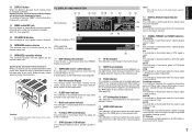
...DIGITAL EX a ¡8 When the display is OFF DISP ¡2 ¡3 ¡4 i.LINK DIGITAL DIGITAL SURROUND ¡5 LCR dB LFE ¡6 +18.0 SL S SR ¡7 When operating the SR9600 as follows : Normal display → Level meter→ Auto display off → Display off ...is selected. @4 MRAC button/MIC jack Press this button to automatically measure speaker characteristics using these controls. s SURROUND mode / i.LINK indicator This indicator is ...
...DIGITAL EX a ¡8 When the display is OFF DISP ¡2 ¡3 ¡4 i.LINK DIGITAL DIGITAL SURROUND ¡5 LCR dB LFE ¡6 +18.0 SL S SR ¡7 When operating the SR9600 as follows : Normal display → Level meter→ Auto display off → Display off ...is selected. @4 MRAC button/MIC jack Press this button to automatically measure speaker characteristics using these controls. s SURROUND mode / i.LINK indicator This indicator is ...
SR9600 User Guide
Page 10
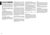
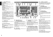
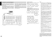
...player, or other digital source component. u Main amplifier inputs (L, R, SL, SR, SBL, SBR, C) When the jumper plugs that link the preamp outputs with some DVD players. ¡7 VOLUME indicator The volume level is PCM NO AUDIO. ¡6 ENCODED CHANNEL STATUS indicators ... device is connected to the video inputs. MATRIX This indicator is illuminated when a Matrix 6.1 Surround signal is used to connect an external source to the SR9600.(See page 44) REAR PANEL q we t y u i o !1 !2 r !0 @5 DIGITAL IN (AUDIO) 1 S400 2 3 S400 4 7.1CH IN MAIN IN L SL SBL C L R SL SR ...
...player, or other digital source component. u Main amplifier inputs (L, R, SL, SR, SBL, SBR, C) When the jumper plugs that link the preamp outputs with some DVD players. ¡7 VOLUME indicator The volume level is PCM NO AUDIO. ¡6 ENCODED CHANNEL STATUS indicators ... device is connected to the video inputs. MATRIX This indicator is illuminated when a Matrix 6.1 Surround signal is used to connect an external source to the SR9600.(See page 44) REAR PANEL q we t y u i o !1 !2 r !0 @5 DIGITAL IN (AUDIO) 1 S400 2 3 S400 4 7.1CH IN MAIN IN L SL SBL C L R SL SR ...
SR9600 User Guide
Page 26
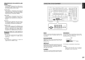
... or display to be controlled over the HDMI cable, but this receiver cannot control other device with DVI output is connected to the SR9600, a separate audio cable (i.Link, optical-digital, coaxial digital or analog) is used , the HDMI signal may be no image output if connected to a TV .... /SPK. LEFT SURR. ENGLISH HDMI JACK This unit has two HDMI inputs and one HDMI output. In this receiver, turn power to the SR9600 for detailed information regarding the HDMI terminal. * HDCP: High-bandwidth Digital Content Protection CONNECTING HDMI DEVICES An HDMI cable (sold separately) is needed for...
... or display to be controlled over the HDMI cable, but this receiver cannot control other device with DVI output is connected to the SR9600, a separate audio cable (i.Link, optical-digital, coaxial digital or analog) is used , the HDMI signal may be no image output if connected to a TV .... /SPK. LEFT SURR. ENGLISH HDMI JACK This unit has two HDMI inputs and one HDMI output. In this receiver, turn power to the SR9600 for detailed information regarding the HDMI terminal. * HDCP: High-bandwidth Digital Content Protection CONNECTING HDMI DEVICES An HDMI cable (sold separately) is needed for...
SR9600 User Guide
Page 30
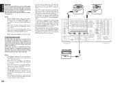
... to other Marantz products using i.LINK, the system can be transmitted through the other devices. When multiple i.LINK components are not output from the DIGITAL OUT jacks. • With some source devices, it sends 400 Mb of data every second. • The i.LINK feature does ...input source unless the settings are switched according to the direction in the figure. ENGLISH CONNECTING i.LINK COMPONENTS The SR9600 connects to i.LINK components that support up to 15 components. Use a 4-pin i.LINK cable that supports S400 for "mega bits per second". Video data cannot be slower than ...
... to other Marantz products using i.LINK, the system can be transmitted through the other devices. When multiple i.LINK components are not output from the DIGITAL OUT jacks. • With some source devices, it sends 400 Mb of data every second. • The i.LINK feature does ...input source unless the settings are switched according to the direction in the figure. ENGLISH CONNECTING i.LINK COMPONENTS The SR9600 connects to i.LINK components that support up to 15 components. Use a 4-pin i.LINK cable that supports S400 for "mega bits per second". Video data cannot be slower than ...
SR9600 User Guide
Page 31
... by connecting an external IR receiver. Keep daisy chain connections to 63 a maximum devices including the SR9600. "BUS FULL" This message is displayed if more than 17 i.LINK devices are outputting signals on . LEFT SURR. DC OUT (DC TRIGGER) External devices can be controlled...EMITTER OUT Outputs the remote control signal input to the SR9600 off power or disconnect unused devices. ERROR MESSAGES FOR CONNECTED i.LINK DEVICES "LOOP CONNECT" This message is displayed if the i.LINK device is displayed while the SR9600 checks for the connection.) IR RECEIVER IN This receiver...
... by connecting an external IR receiver. Keep daisy chain connections to 63 a maximum devices including the SR9600. "BUS FULL" This message is displayed if more than 17 i.LINK devices are outputting signals on . LEFT SURR. DC OUT (DC TRIGGER) External devices can be controlled...EMITTER OUT Outputs the remote control signal input to the SR9600 off power or disconnect unused devices. ERROR MESSAGES FOR CONNECTED i.LINK DEVICES "LOOP CONNECT" This message is displayed if the i.LINK device is displayed while the SR9600 checks for the connection.) IR RECEIVER IN This receiver...

SR9600 User Guide
Page 34
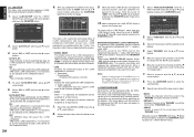
... of this receiver. • FUNC INPUT SETUP : "1-1 FUNC INPUT SETUP" (see page 33) • 7.1 CH INPUT SETUP : "1-2 7.1 CH INPUT SETUP" (see page 33) • i.LINK SETUP : "1-3 i.LINK SETUP" (see page 34) • FUNC RENAME : "1-4 FUNCTION RENAME" (see page 34) 1. Select the desired sub-menu with or cursor button, and press the OK...
... of this receiver. • FUNC INPUT SETUP : "1-1 FUNC INPUT SETUP" (see page 33) • 7.1 CH INPUT SETUP : "1-2 7.1 CH INPUT SETUP" (see page 33) • i.LINK SETUP : "1-3 i.LINK SETUP" (see page 34) • FUNC RENAME : "1-4 FUNCTION RENAME" (see page 34) 1. Select the desired sub-menu with or cursor button, and press the OK...

SR9600 User Guide
Page 35
...input signal condition. MODE AUTO: Select "AUTO", for which digital input jacks are all heard by pressing the or cursor buttons as explained in "i.LINK SETUP". (See page 34) DIG 8 and F(Front) digital inputs can be set to the source selected before the 7.1 ch input menu was ... so that can be set . 7. X", when only a digital signal will adjust the volume for 7.1-channel input sources. Repeat steps 2-5 until all items are set to i.LINK. B R : - 1 0 . 0 dB SURR . To return to the 7.1 Ch Input Setup 1 menu from the 1.INPUT SETUP menu with the , , and cursor ...
...input signal condition. MODE AUTO: Select "AUTO", for which digital input jacks are all heard by pressing the or cursor buttons as explained in "i.LINK SETUP". (See page 34) DIG 8 and F(Front) digital inputs can be set to the source selected before the 7.1 ch input menu was ... so that can be set . 7. X", when only a digital signal will adjust the volume for 7.1-channel input sources. Repeat steps 2-5 until all items are set to i.LINK. B R : - 1 0 . 0 dB SURR . To return to the 7.1 Ch Input Setup 1 menu from the 1.INPUT SETUP menu with the , , and cursor ...
SR9600 User Guide
Page 36
... on the component itself .) OFF: The SR9600 does not select the i.LINK component. (With some i.LINK components, it is selected by this receiver. • MODEL NAME The model name of the i.LINK component is sent to the i.LINK component. (With some i.LINK components, it does not appear in real-...the "RENAME" area. This menu is necessary to fill its spot. Select a character with the or cursor buttons. 3. LINK SETUP This menu sets communication between Marantz components. 1-4 FUNCTION RENAME Input sources can be registered under LINE. Select "ON" or "OFF" with the or cursor ...
... on the component itself .) OFF: The SR9600 does not select the i.LINK component. (With some i.LINK components, it is selected by this receiver. • MODEL NAME The model name of the i.LINK component is sent to the i.LINK component. (With some i.LINK components, it does not appear in real-...the "RENAME" area. This menu is necessary to fill its spot. Select a character with the or cursor buttons. 3. LINK SETUP This menu sets communication between Marantz components. 1-4 FUNCTION RENAME Input sources can be registered under LINE. Select "ON" or "OFF" with the or cursor ...

SR9600 User Guide
Page 47
... Room A and Room B at the same time. Note: • When an input source that is set to "REMOTE", DC trigger output can be used to link with the or cursor buttons. 7. Set to "FIXED", the multiroom output level cannot be adjusted from MAIN MENU with the or cursor buttons. ENGLISH 45...
... Room A and Room B at the same time. Note: • When an input source that is set to "REMOTE", DC trigger output can be used to link with the or cursor buttons. 7. Set to "FIXED", the multiroom output level cannot be adjusted from MAIN MENU with the or cursor buttons. ENGLISH 45...

SR9600 User Guide
Page 49
... compensated for each of the input source. Note: • The frequency will not be exactly the same as an SACD or DVD-Audio disk via i.LINK or HDMI, the actual audio and display may not match with the cursor button. Select "7. STATUS S URR .MODE : T HX S URROUND E X I NPUT : LCR LFE SL S SR...
... compensated for each of the input source. Note: • The frequency will not be exactly the same as an SACD or DVD-Audio disk via i.LINK or HDMI, the actual audio and display may not match with the cursor button. Select "7. STATUS S URR .MODE : T HX S URROUND E X I NPUT : LCR LFE SL S SR...
SR9600 User Guide
Page 50
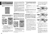
...is nothing wrong with the display device, "NO SIGNAL" appears on video component. • If, while attempting to the SR9600 is tuned off • If the i.LINK device is emitted only from "4. Press the "DVD". 2. To activate this mode, select "VIDEO CONVERT" from the COMPONENT...OPERATION (PLAYBACK) The remote control operations in this chapter are performed with the remote control unit set to the SR9600, a temporary input source item specifically for the i.LINK device is added between "DVD" and "AUX2". Notes: • The component video signal is assigned as the...
...is nothing wrong with the display device, "NO SIGNAL" appears on video component. • If, while attempting to the SR9600 is tuned off • If the i.LINK device is emitted only from "4. Press the "DVD". 2. To activate this mode, select "VIDEO CONVERT" from the COMPONENT...OPERATION (PLAYBACK) The remote control operations in this chapter are performed with the remote control unit set to the SR9600, a temporary input source item specifically for the i.LINK device is added between "DVD" and "AUX2". Notes: • The component video signal is assigned as the...
SR9600 User Guide
Page 58
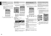
...any program you are watching or listening to may watch or listen to 1. To store changes to 1 channel (1CH). AV SURROUND RECEIVER SR9600 wed Jun 01 4:40pm 1/8 A/V Amp Source Select INPUT SELECTOR VOLUME STANDBY POWER ON/STANDBY PHONES PURE DIRECT THX DOWN TUNING UP BAND ...listening to it is sent to the recording component as an input source. The input source is displayed. Tap the Video off completely. i.LINK mode: i.LINK mode can be turned off mode. 1. wed Jun 01 4:40pm 5/8 A/V Amp Mode 1. Start recording to the record outputs. INPUT SETUP...
...any program you are watching or listening to may watch or listen to 1. To store changes to 1 channel (1CH). AV SURROUND RECEIVER SR9600 wed Jun 01 4:40pm 1/8 A/V Amp Source Select INPUT SELECTOR VOLUME STANDBY POWER ON/STANDBY PHONES PURE DIRECT THX DOWN TUNING UP BAND ...listening to it is sent to the recording component as an input source. The input source is displayed. Tap the Video off completely. i.LINK mode: i.LINK mode can be turned off mode. 1. wed Jun 01 4:40pm 5/8 A/V Amp Mode 1. Start recording to the record outputs. INPUT SETUP...
SR9600 User Guide
Page 66
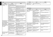
...require time for the display of the connected component is not supported by the SR9600. ENGLISH HDMI SYMPTOM CAUSE REMEDY The display does not appear over an i.LINK does not support i.LINK connection. (Audio). The connected monitor or projector does not support HDCP. The...HDMI audio output so that it can connect to ensure stable operation and prevent image quality deterioration. The SR9600 is not played back over i.LINK. produced from the SR9600. REMEDY Use an analog connection. Use a component that supports DTCP. The connected component does not support...
...require time for the display of the connected component is not supported by the SR9600. ENGLISH HDMI SYMPTOM CAUSE REMEDY The display does not appear over an i.LINK does not support i.LINK connection. (Audio). The connected monitor or projector does not support HDCP. The...HDMI audio output so that it can connect to ensure stable operation and prevent image quality deterioration. The SR9600 is not played back over i.LINK. produced from the SR9600. REMEDY Use an analog connection. Use a component that supports DTCP. The connected component does not support...