
User Guide
Page 4
... following two conditions: (1) this device may cause harmful interference to radio communications. Operation is no guarantee that may cause undesired operation. iv Micro-Star International MS-7173 This device complies with Part 15 of the FCC Rules. Notice 2 Shielded interface cables and A.C. VOIR LANOTICE D'INSTALLATIONAVANT DE RACCORDER AU RESEAU. power cord...
... following two conditions: (1) this device may cause harmful interference to radio communications. Operation is no guarantee that may cause undesired operation. iv Micro-Star International MS-7173 This device complies with Part 15 of the FCC Rules. Notice 2 Shielded interface cables and A.C. VOIR LANOTICE D'INSTALLATIONAVANT DE RACCORDER AU RESEAU. power cord...
User Guide
Page 11
Getting Started Chapter 1 Getting Started Thank you for optimal system efficiency. The RC410M2 Series mainboards are based on AT I® RC410S & SB600 chipsets for choosing the RC410M2 Series (MS-7173 v2.X) Micro-ATX mainboard. Designed to fit the advanced Intel® Pentium 4, Cedar Mill, and Celeron D processors, the RC410M2 Series deliver a high performance and professional desktop platform solution. 1-1
Getting Started Chapter 1 Getting Started Thank you for optimal system efficiency. The RC410M2 Series mainboards are based on AT I® RC410S & SB600 chipsets for choosing the RC410M2 Series (MS-7173 v2.X) Micro-ATX mainboard. Designed to fit the advanced Intel® Pentium 4, Cedar Mill, and Celeron D processors, the RC410M2 Series deliver a high performance and professional desktop platform solution. 1-1
User Guide
Page 12
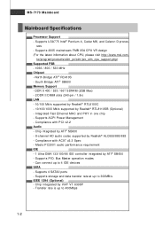
...; SB600 - Compliance with AC97 v2.3 Spec - Can connect up to 400Mbps 1-2 Transfer rate is up to 300MB/s IEEE 1394 (Optional) - North Bridge: ATI® RC410S - MS-7173 Mainboard Mainboard Specifications Processor Support - Chip integrated by ATI® SB600 - 8-channel HD audio codec supported by VIA® VT 6308P - Supports storage and... integrated by Realtek® ALC655/880/883 - Supports 2005 mainstream FMB 05A CPU VR design (For the latest information about CPU, please visit http://www.msi.com. sors - Supports PIO, Bus Master operation modes -
...; SB600 - Compliance with AC97 v2.3 Spec - Can connect up to 400Mbps 1-2 Transfer rate is up to 300MB/s IEEE 1394 (Optional) - North Bridge: ATI® RC410S - MS-7173 Mainboard Mainboard Specifications Processor Support - Chip integrated by ATI® SB600 - 8-channel HD audio codec supported by VIA® VT 6308P - Supports storage and... integrated by Realtek® ALC655/880/883 - Supports 2005 mainstream FMB 05A CPU VR design (For the latest information about CPU, please visit http://www.msi.com. sors - Supports PIO, Bus Master operation modes -
User Guide
Page 14
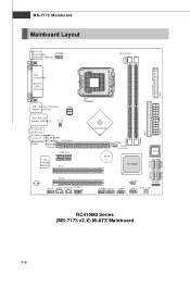
FDD 1 MS-7173 Mainboard Mainboard Layout Top: Mouse JCOM1 Bottom: Keyboard CPU_FAN1 Top: Parallel Port Bottom: COM 1 VGA Port Top: 1394 Port (Optional) Bottom: USB Ports JPW1 ...) PCIE 1X1 PCI1 ATI RC410S BATT + ATI SB600 BIOS ALC883 PCI 2 JAUD1 JCD1 SPDOUT J1394_1 (Optional) JBAT1 JLPC1 JUSB3 JUS B1 JUS B2 JFP1 SYS_FAN RC410M2 Series (MS-7173 v2.X) M-ATX Mainboard DIMM1 DIMM2 IDE1 ATX1 SATA4 SATA2 SATA3 SATA1 1-4
FDD 1 MS-7173 Mainboard Mainboard Layout Top: Mouse JCOM1 Bottom: Keyboard CPU_FAN1 Top: Parallel Port Bottom: COM 1 VGA Port Top: 1394 Port (Optional) Bottom: USB Ports JPW1 ...) PCIE 1X1 PCI1 ATI RC410S BATT + ATI SB600 BIOS ALC883 PCI 2 JAUD1 JCD1 SPDOUT J1394_1 (Optional) JBAT1 JLPC1 JUSB3 JUS B1 JUS B2 JFP1 SYS_FAN RC410M2 Series (MS-7173 v2.X) M-ATX Mainboard DIMM1 DIMM2 IDE1 ATX1 SATA4 SATA2 SATA3 SATA1 1-4
User Guide
Page 17
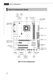
MS-7173 Mainboard Quick Components Guide JTV1, JPW1, p.2-21 p.2-11 (Optional) JCOM1, p.2-18 CPU, p.2-3 CPU_FAN1, p.2-15 Rear Panel I/O, p.2-12 DDR DIMMs, p.2-8 FDD1, p.2-15 ATX1, p.2-10 PCI Express Slots, p.2-25 PCI Slots, p.2-25 IDE1, p.2-16 SATA 1-4, p.2-17 JLPC1, p.2-23 JBAT, p.2-24 JAUD1, p.2-18 SPDOUT, p.2-22 (Optional) JUSB1-3 p.2-20 JCD1, p.2-18 J1394_1, p.2-19 (Optional) SYS_FAN, p.2-15 JFP1, p.2-20 MS-7173 (V2.X) Mainboard 2-2
MS-7173 Mainboard Quick Components Guide JTV1, JPW1, p.2-21 p.2-11 (Optional) JCOM1, p.2-18 CPU, p.2-3 CPU_FAN1, p.2-15 Rear Panel I/O, p.2-12 DDR DIMMs, p.2-8 FDD1, p.2-15 ATX1, p.2-10 PCI Express Slots, p.2-25 PCI Slots, p.2-25 IDE1, p.2-16 SATA 1-4, p.2-17 JLPC1, p.2-23 JBAT, p.2-24 JAUD1, p.2-18 SPDOUT, p.2-22 (Optional) JUSB1-3 p.2-20 JCD1, p.2-18 J1394_1, p.2-19 (Optional) SYS_FAN, p.2-15 JFP1, p.2-20 MS-7173 (V2.X) Mainboard 2-2
User Guide
Page 19
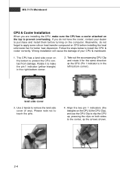
... 1 indicators (the triangles on the CPU & the CPU Clip), and use the CPU Clip to clip the CPU up, pressing the clips on the computer. MS-7173 Mainboard CPU & Cooler Installation W hen you do not forget to remove the land side cover (if any). The CPU has a land side cover on...
... 1 indicators (the triangles on the CPU & the CPU Clip), and use the CPU Clip to clip the CPU up, pressing the clips on the computer. MS-7173 Mainboard CPU & Cooler Installation W hen you do not forget to remove the land side cover (if any). The CPU has a land side cover on...
User Guide
Page 21
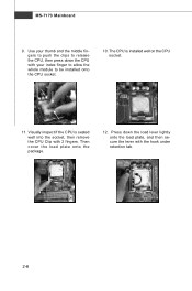
Press down the CPU with your index finger to allow the whole module to release the CPU, then press down the load lever lightly onto the load plate, and then secure the lever with 2 fingers. MS-7173 Mainboard 9. Visually inspect if the CPU is installed well on the CPU socket. 11. Then cover the load plate onto the p ac kage. 12. Use your thumb and the middle fingers to push the clips to be installed onto the CPU socket. 10. The CPU is seated well into the socket, then remove the CPU Clip with the hook under retention tab. 2-6
Press down the CPU with your index finger to allow the whole module to release the CPU, then press down the load lever lightly onto the load plate, and then secure the lever with 2 fingers. MS-7173 Mainboard 9. Visually inspect if the CPU is installed well on the CPU socket. 11. Then cover the load plate onto the p ac kage. 12. Use your thumb and the middle fingers to push the clips to be installed onto the CPU socket. 10. The CPU is seated well into the socket, then remove the CPU Clip with the hook under retention tab. 2-6
User Guide
Page 23
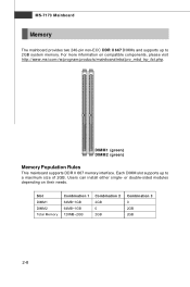
... Total Memory Combination 1 64MB~1GB 64MB~1GB 128MB~2GB Combination 2 2GB 0 2GB Combination 3 0 2GB 2GB 2-8 For more information on their needs. MS-7173 Mainboard Memory The mainboard provides two 240-pin non-ECC DDR II 667 DIMMs and supports up to 2GB system memory. Users can install... either single- or double-sided modules depending on compatible components, please visit ht tp:/ /ww w.ms i.c om.t w/p rogr am/ prod uc t s /m ainb oar d/mb d/p ro_m bd_ trp_ lis t.ph p. DIMM1 (green) DIMM2 (green) Memory Population Rules This...
... Total Memory Combination 1 64MB~1GB 64MB~1GB 128MB~2GB Combination 2 2GB 0 2GB Combination 3 0 2GB 2GB 2-8 For more information on their needs. MS-7173 Mainboard Memory The mainboard provides two 240-pin non-ECC DDR II 667 DIMMs and supports up to 2GB system memory. Users can install... either single- or double-sided modules depending on compatible components, please visit ht tp:/ /ww w.ms i.c om.t w/p rogr am/ prod uc t s /m ainb oar d/mb d/p ro_m bd_ trp_ lis t.ph p. DIMM1 (green) DIMM2 (green) Memory Population Rules This...
User Guide
Page 25
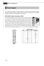
... to the image at the right hand). pin 13 To connect the ATX 24-pin power supply, make sure that no damage will be caused. MS-7173 Mainboard Power Supply The mainboard supports ATX power supply for the power system.
... to the image at the right hand). pin 13 To connect the ATX 24-pin power supply, make sure that no damage will be caused. MS-7173 Mainboard Power Supply The mainboard supports ATX power supply for the power system.
User Guide
Page 27
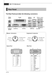
MS-7173 Mainboard Rear Panel The Rear Panel provides the following connectors: Mouse (green) Parallel 1394 Port (Optional) LAN CS-Out Line-In RS-Out Line-...
MS-7173 Mainboard Rear Panel The Rear Panel provides the following connectors: Mouse (green) Parallel 1394 Port (Optional) LAN CS-Out Line-In RS-Out Line-...
User Guide
Page 29
MS-7173 Mainboard Serial Ports The mainboard offers two 9-pins male DIN connectors as the Side-Surround Out. USB Connectors The OHCI (Open Host Controller Interface) ...
MS-7173 Mainboard Serial Ports The mainboard offers two 9-pins male DIN connectors as the Side-Surround Out. USB Connectors The OHCI (Open Host Controller Interface) ...
User Guide
Page 31
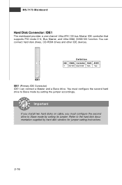
You must configure the second drive to Slave mode by setting its jumper. MS-7173 Mainboard Hard Disk Connector: IDE1 The mainboard provides a one-channel Ultra ATA 100 bus Master IDE controller that supports PIO mode 0~4, Bus Master, and ...
You must configure the second drive to Slave mode by setting its jumper. MS-7173 Mainboard Hard Disk Connector: IDE1 The mainboard provides a one-channel Ultra ATA 100 bus Master IDE controller that supports PIO mode 0~4, Bus Master, and ...
User Guide
Page 33
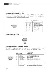
... Ready Ground Data Set Ready Request To Send Clear To Send Ring Indicate CD-In Connector: JCD1 This connector is provided for CD-ROM audio. MS-7173 Mainboard Serial Port Connector: JCOM1 The mainboard provides one 9-pin header as serial port JCOM1.
... Ready Ground Data Set Ready Request To Send Clear To Send Ring Indicate CD-In Connector: JCD1 This connector is provided for CD-ROM audio. MS-7173 Mainboard Serial Port Connector: JCOM1 The mainboard provides one 9-pin header as serial port JCOM1.
User Guide
Page 35
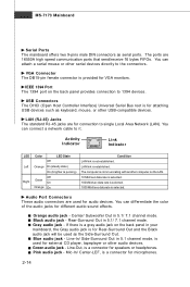
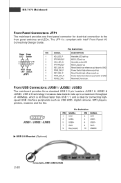
... pull-up to a maximum throughput of 480Mbps, which is 40 times faster than USB 1.1, and is compliant with Intel® Front Panel I/O Connectivity Design Guide. MS-7173 Mainboard Front Panel Connectors: JFP1 The mainboard provides one front panel connector for connecting highspeed USB interface peripherals such as USB HDD, digital cameras...
... pull-up to a maximum throughput of 480Mbps, which is 40 times faster than USB 1.1, and is compliant with Intel® Front Panel I/O Connectivity Design Guide. MS-7173 Mainboard Front Panel Connectors: JFP1 The mainboard provides one front panel connector for connecting highspeed USB interface peripherals such as USB HDD, digital cameras...
User Guide
Page 37
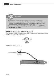
... TVs. 2. Simultaneous connection (of this bracket) to two TVs is used to Appendix D: Using the TV-Out Function (HDTV-Out Integrated) for digital audio transmission. MS-7173 Mainboard Important 1. SPDIF-Out Connector: SPDOUT (Optional) This connector is prohibited and may lead to one TV only.
... TVs. 2. Simultaneous connection (of this bracket) to two TVs is used to Appendix D: Using the TV-Out Function (HDTV-Out Integrated) for digital audio transmission. MS-7173 Mainboard Important 1. SPDIF-Out Connector: SPDOUT (Optional) This connector is prohibited and may lead to one TV only.
User Guide
Page 42
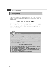
... digit refers to BIOS maker as A= AMI, W= AWARD, and P= PHOENIX. 2nd - 5th digit refers to the model number. 6th digit refers to the chipset as MS= all standard customers. It is the BIOS version. When the message below appears on the computer and the system will start POST (Power On Self... be held for better system performance. Therefore, the description may also restart the system by turning it OFF and On or pressing the RESET button. MS-7173 M ainboard Entering Setup Power on the screen, press key to the date this chapter are under each BIOS category described in this BIOS was...
... digit refers to BIOS maker as A= AMI, W= AWARD, and P= PHOENIX. 2nd - 5th digit refers to the model number. 6th digit refers to the chipset as MS= all standard customers. It is the BIOS version. When the message below appears on the computer and the system will start POST (Power On Self... be held for better system performance. Therefore, the description may also restart the system by turning it OFF and On or pressing the RESET button. MS-7173 M ainboard Entering Setup Power on the screen, press key to the date this chapter are under each BIOS category described in this BIOS was...
User Guide
Page 44
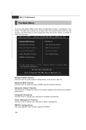
... menu to specify your system's performance. Use arrow keys to select among the items and press to setup the items of BIOS special enhanced features. MS-7173 M ainboard The Main Menu Once you to select from nine setup functions and two exit choices. Advanced Chipset Features Use this menu to accept...
... menu to specify your system's performance. Use arrow keys to select among the items and press to setup the items of BIOS special enhanced features. MS-7173 M ainboard The Main Menu Once you to select from nine setup functions and two exit choices. Advanced Chipset Features Use this menu to accept...
User Guide
Page 46
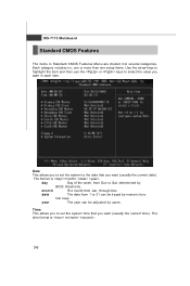
.... date The date from 1 to Sat, determined by BIOS. The format is . 3-6 Read-only. year The year can be adjusted by numeric func tion keys. MS-7173 M ainboard Standard CMOS Features The items in each item. through Dec. Each category includes no, one or more than one setup items. Use the...
.... date The date from 1 to Sat, determined by BIOS. The format is . 3-6 Read-only. year The year can be adjusted by numeric func tion keys. MS-7173 M ainboard Standard CMOS Features The items in each item. through Dec. Each category includes no, one or more than one setup items. Use the...
User Guide
Page 48
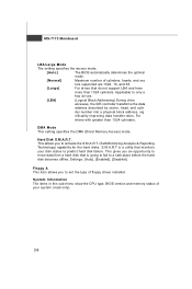
...]. This gives you an opportunity to move data from a hard disk that is a utility that do not support LBA and have more than 1024 cylinders. MS-7173 M ainboard LBA/Large M ode The setting specifies the access mode. [ Au to ] The BIOS automatically determines the optimal mode. [Nor m al ] Maximum number of...
...]. This gives you an opportunity to move data from a hard disk that is a utility that do not support LBA and have more than 1024 cylinders. MS-7173 M ainboard LBA/Large M ode The setting specifies the access mode. [ Au to ] The BIOS automatically determines the optimal mode. [Nor m al ] Maximum number of...
User Guide
Page 50
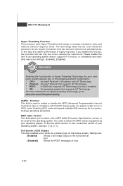
...: An operating system that can execute instructions simultaneously. Settings: [Enabled], [Disabled]. To find out which MPS (Multi-Processor Specification) version to run in APIC mode. MS-7173 M ainboard Hyper-Threading Function The processor uses Hyper-Threading technology to show the company logo on the full screen at boot. [ Di sa bl...
...: An operating system that can execute instructions simultaneously. Settings: [Enabled], [Disabled]. To find out which MPS (Multi-Processor Specification) version to run in APIC mode. MS-7173 M ainboard Hyper-Threading Function The processor uses Hyper-Threading technology to show the company logo on the full screen at boot. [ Di sa bl...


