
User Guide
Page 2
...://support.msi.com.tw ii AMD, Athlon™, Athlon™ XP, Thoroughbred™, and Duron™ are registered trademarks of AMD Corporation. PS/2 and OS®/2 are the properties of Phoenix Technologies Ltd. Netware® is a registered trademark of Microsoft Corporation. Alternatively, please try the following help resources for FAQ, technical guide, BIOS updates, driver updates, and other countries. Award®...
...://support.msi.com.tw ii AMD, Athlon™, Athlon™ XP, Thoroughbred™, and Duron™ are registered trademarks of AMD Corporation. PS/2 and OS®/2 are the properties of Phoenix Technologies Ltd. Netware® is a registered trademark of Microsoft Corporation. Alternatively, please try the following help resources for FAQ, technical guide, BIOS updates, driver updates, and other countries. Award®...
User Guide
Page 8
... Specifications 1-2 Mainboard Layout 1-4 Packing Checklist 1-5 Chapter 2. Hardware Setup 2-1 Quick Components Guide 2-2 Central Processing Unit: CPU 2-3 Introduction to LGA 775 CPU 2-3 CPU & Cooler Installation 2-4 Memory...2-8 Memory Population Rules 2-8 Installing DDR II Modules 2-9 Power Supply...2-10 ATX 24-Pin Power Connector: ATX1 2-10 ATX 12V Power Connector: JPW 1 2-11 Rear Panel...2-12 Connectors...2-15 Floppy Disk Drive Connector: FDD1 2-15 Fan Power Connectors: CPU_FAN1 / SYS_FAN 2-15 Hard Disk Connector: IDE1 2-16 Serial ATA Connectors: SATA1~SATA4 2-17 Serial Port...
... Specifications 1-2 Mainboard Layout 1-4 Packing Checklist 1-5 Chapter 2. Hardware Setup 2-1 Quick Components Guide 2-2 Central Processing Unit: CPU 2-3 Introduction to LGA 775 CPU 2-3 CPU & Cooler Installation 2-4 Memory...2-8 Memory Population Rules 2-8 Installing DDR II Modules 2-9 Power Supply...2-10 ATX 24-Pin Power Connector: ATX1 2-10 ATX 12V Power Connector: JPW 1 2-11 Rear Panel...2-12 Connectors...2-15 Floppy Disk Drive Connector: FDD1 2-15 Fan Power Connectors: CPU_FAN1 / SYS_FAN 2-15 Hard Disk Connector: IDE1 2-16 Serial ATA Connectors: SATA1~SATA4 2-17 Serial Port...
User Guide
Page 9
Jumper...2-24 Clear CMOS Jumper: JBAT1 2-24 Slots...2-25 PCI (Peripheral Component Interconnect) Express Slots 2-25 PCI (Peripheral Component Interconnect) Slots 2-25 PCI Interrupt Request Routing 2-25 Chapter 3. BIOS Setup 3-1 Entering Setup...3-2 Control Keys 3-3 Getting Help 3-3 General Help
Jumper...2-24 Clear CMOS Jumper: JBAT1 2-24 Slots...2-25 PCI (Peripheral Component Interconnect) Express Slots 2-25 PCI (Peripheral Component Interconnect) Slots 2-25 PCI Interrupt Request Routing 2-25 Chapter 3. BIOS Setup 3-1 Entering Setup...3-2 Control Keys 3-3 Getting Help 3-3 General Help
User Guide
Page 12
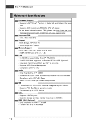
... with AC97 v2.3 Spec - Compliance with PCI v2.2 Audio - Supports PIO, Bus Master operation modes - Supports ACPI Power Management - South Bridge: ATI® SB600 Memory Support - Can connect up to 400Mbps 1-2 Transfer rate is up to 300MB/s IEEE 1394 (Optional) - MS-7173 Mainboard Mainboard Specifications Processor Support - t w / program / produc t s/ slim _pc /sl m / pro_sl m _c pu_support .php) Supported FSB - 1066 / 800 / 533 MHz Chipset - Supports 2005 mainstream FMB 05A CPU VR design (For...
... with AC97 v2.3 Spec - Compliance with PCI v2.2 Audio - Supports PIO, Bus Master operation modes - Supports ACPI Power Management - South Bridge: ATI® SB600 Memory Support - Can connect up to 400Mbps 1-2 Transfer rate is up to 300MB/s IEEE 1394 (Optional) - MS-7173 Mainboard Mainboard Specifications Processor Support - t w / program / produc t s/ slim _pc /sl m / pro_sl m _c pu_support .php) Supported FSB - 1066 / 800 / 533 MHz Chipset - Supports 2005 mainstream FMB 05A CPU VR design (For...
User Guide
Page 23
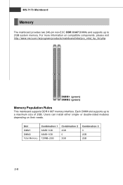
.... Slot DIMM1 DIMM2 Total Memory Combination 1 64MB~1GB 64MB~1GB 128MB~2GB Combination 2 2GB 0 2GB Combination 3 0 2GB 2GB 2-8 Each DIMM slot supports up to a maximum size of 2GB. MS-7173 Mainboard Memory The mainboard provides two 240-pin non-ECC DDR II 667 DIMMs and supports up to 2GB system memory. DIMM1 (green) DIMM2 (green) Memory Population Rules This mainboard supports DDR II 667 memory...
.... Slot DIMM1 DIMM2 Total Memory Combination 1 64MB~1GB 64MB~1GB 128MB~2GB Combination 2 2GB 0 2GB Combination 3 0 2GB 2GB 2-8 Each DIMM slot supports up to a maximum size of 2GB. MS-7173 Mainboard Memory The mainboard provides two 240-pin non-ECC DDR II 667 DIMMs and supports up to 2GB system memory. DIMM1 (green) DIMM2 (green) Memory Population Rules This mainboard supports DDR II 667 memory...
User Guide
Page 31
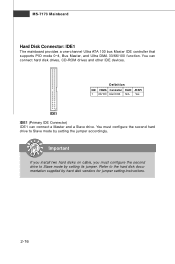
... jumper. Important If you install two hard disks on cable, you must configure the second hard drive to the hard disk documentation supplied by setting the jumper accordingly. Refer to Slave mode by hard disk vendors for jumper setting instructions. 2-16 Definition IDE VDMA Controller RAID ATAPI 1 66/100 Intel ICH6 N/A Yes IDE1 IDE1 (Primary IDE Connector) IDE1 can connect hard disk drives, CD-ROM drives and other IDE devices. MS-7173 Mainboard Hard Disk Connector: IDE1 The mainboard provides a one-channel Ultra ATA 100 bus Master IDE controller that supports PIO mode 0~4, Bus...
... jumper. Important If you install two hard disks on cable, you must configure the second hard drive to the hard disk documentation supplied by setting the jumper accordingly. Refer to Slave mode by hard disk vendors for jumper setting instructions. 2-16 Definition IDE VDMA Controller RAID ATAPI 1 66/100 Intel ICH6 N/A Yes IDE1 IDE1 (Primary IDE Connector) IDE1 can connect hard disk drives, CD-ROM drives and other IDE devices. MS-7173 Mainboard Hard Disk Connector: IDE1 The mainboard provides a one-channel Ultra ATA 100 bus Master IDE controller that supports PIO mode 0~4, Bus...
User Guide
Page 33
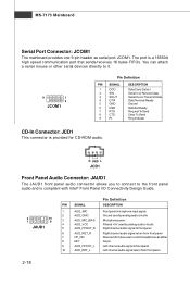
... panel audio and is compliant with Intel® Front Panel I/O Connectivity Design Guide. 2 10 1 9 JAUD1 PIN SIGNAL Pin Definition DESCRIPTION 1 AUD_MIC Front panel microphone input signal 2 AUD_GND Ground used by analog audio circuits 3 AUD_MIC_BIAS Microphone power 4 AUD_VCC Filtered +5V used by analog audio circuits 5 AUD_FPOUT_R Right channel audio signal to front panel 6 AUD_RET_R Right channel audio signal return from front panel 2-18 MS-7173 Mainboard Serial Port Connector: JCOM1 The mainboard provides one 9-pin header as serial port...
... panel audio and is compliant with Intel® Front Panel I/O Connectivity Design Guide. 2 10 1 9 JAUD1 PIN SIGNAL Pin Definition DESCRIPTION 1 AUD_MIC Front panel microphone input signal 2 AUD_GND Ground used by analog audio circuits 3 AUD_MIC_BIAS Microphone power 4 AUD_VCC Filtered +5V used by analog audio circuits 5 AUD_FPOUT_R Right channel audio signal to front panel 6 AUD_RET_R Right channel audio signal return from front panel 2-18 MS-7173 Mainboard Serial Port Connector: JCOM1 The mainboard provides one 9-pin header as serial port...
User Guide
Page 39
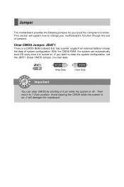
... to change your motherboard's function through the use of system configuration. With the CMOS RAM, the system can clear CMOS by shorting 2-3 pin while the system is turned on ; Jumper The motherboard provides the following jumpers for you want to clear the system configuration, set the computer's function. If you to set the JBAT1 (Clear CMOS Jumper ) to keep the data of jumpers. it is off. This section will damage the mainboard. Clear CMOS Jumper: JBAT1...
... to change your motherboard's function through the use of system configuration. With the CMOS RAM, the system can clear CMOS by shorting 2-3 pin while the system is turned on ; Jumper The motherboard provides the following jumpers for you want to clear the system configuration, set the computer's function. If you to set the JBAT1 (Clear CMOS Jumper ) to keep the data of jumpers. it is off. This section will damage the mainboard. Clear CMOS Jumper: JBAT1...
User Guide
Page 40
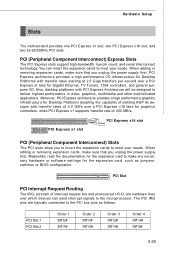
... the PCI bus pins as jumpers, switches or BIOS configuration. PCI Express x16 slot PCI Express x1 slot PCI (Peripheral Component Interconnect) Slots The PCI slots allow you unplug the power supply first. The PCI IRQ pins are hardware lines over a PCI Express x16 lane for graphics controllers, while PCI Express x1 supports transfer rate of 250 MB/s. Hardware Setup Slots The motherboard provides one PCI Express x1 slot, one PCI Express x16 slot, and two 32-bit/33MHz PCI slots. W hen adding or removing expansion cards, make any necessary hardware or software settings...
... the PCI bus pins as jumpers, switches or BIOS configuration. PCI Express x16 slot PCI Express x1 slot PCI (Peripheral Component Interconnect) Slots The PCI slots allow you unplug the power supply first. The PCI IRQ pins are hardware lines over a PCI Express x16 lane for graphics controllers, while PCI Express x1 supports transfer rate of 250 MB/s. Hardware Setup Slots The motherboard provides one PCI Express x1 slot, one PCI Express x16 slot, and two 32-bit/33MHz PCI slots. W hen adding or removing expansion cards, make any necessary hardware or software settings...
User Guide
Page 47
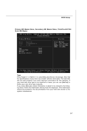
... keyboard. If your hard disk drive type is asked to the following items. Enter the information directly from your hard disk vendor or the system manufacturer. 3-7 BIOS Setup Primary IDE Master/Slave, Secondary IDE Master/Slave, Third/Fourth/Fifth/ Sixth IDE Master Ty pe Press PgUp/ or PgDn/ to define your own drive type manually. The hard disk will not work properly if you can use [Manual] to select [Manual], [None] or [Auto] type...
... keyboard. If your hard disk drive type is asked to the following items. Enter the information directly from your hard disk vendor or the system manufacturer. 3-7 BIOS Setup Primary IDE Master/Slave, Secondary IDE Master/Slave, Third/Fourth/Fifth/ Sixth IDE Master Ty pe Press PgUp/ or PgDn/ to define your own drive type manually. The hard disk will not work properly if you can use [Manual] to select [Manual], [None] or [Auto] type...
User Guide
Page 48
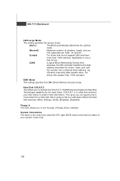
... setting specifies the DMA (Direct Memory Access) mode. This allows you to set the type of floppy drives installed. This gives you an opportunity to move data from a hard disk that monitors your system (read only). 3-8 System Information The items in this sub-menu show the CPU type, BIOS version and memory status of your disk status to predict hard disk failure. Hard Disk S.M.A.R.T. Applicable to only a few drives. [LBA] (Logical Block Addressing) During drive accesses, the IDE controller...
... setting specifies the DMA (Direct Memory Access) mode. This allows you to set the type of floppy drives installed. This gives you an opportunity to move data from a hard disk that monitors your system (read only). 3-8 System Information The items in this sub-menu show the CPU type, BIOS version and memory status of your disk status to predict hard disk failure. Hard Disk S.M.A.R.T. Applicable to only a few drives. [LBA] (Logical Block Addressing) During drive accesses, the IDE controller...
User Guide
Page 50
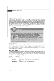
...; Chipset that supports HT Technology; * BIOS: A BIOS that supports HT Technology and has it enabled; * OS: An operating system that can execute instructions simultaneously. To find out which MPS (Multi-Processor Specification) version to be used to increase transaction rates and reduces end-user response times. MS-7173 M ainboard Hyper-Threading Function The processor uses Hyper-Threading technology to enable or disable the APIC (Advanced Programmable Interrupt Controller). The technology treats...
...; Chipset that supports HT Technology; * BIOS: A BIOS that supports HT Technology and has it enabled; * OS: An operating system that can execute instructions simultaneously. To find out which MPS (Multi-Processor Specification) version to be used to increase transaction rates and reduces end-user response times. MS-7173 M ainboard Hyper-Threading Function The processor uses Hyper-Threading technology to enable or disable the APIC (Advanced Programmable Interrupt Controller). The technology treats...
User Guide
Page 54
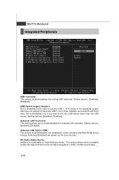
... users to enable/disable the onboard LAN controller. MS-7173 M ainboard Integrated Peripherals USB Controller This setting disables/enables the onchip USB controller. Onboard LAN Option ROM This setting enables/disables the initialization of "High Definition Audio." USB Device Legacy Support Set to [Enabled] if your need to use any USB 1.1/2.0 device in ICH6 / ICH6R southbridge. 3-14 Onboard LAN Controller This setting allows you want to use any USB 1.1/2.0 driver installed, such as DOS and SCO Unix. HD Audio Azalia Device Azalia is the codename of the onboard LAN Boot ROM...
... users to enable/disable the onboard LAN controller. MS-7173 M ainboard Integrated Peripherals USB Controller This setting disables/enables the onchip USB controller. Onboard LAN Option ROM This setting enables/disables the initialization of "High Definition Audio." USB Device Legacy Support Set to [Enabled] if your need to use any USB 1.1/2.0 device in ICH6 / ICH6R southbridge. 3-14 Onboard LAN Controller This setting allows you want to use any USB 1.1/2.0 driver installed, such as DOS and SCO Unix. HD Audio Azalia Device Azalia is the codename of the onboard LAN Boot ROM...
User Guide
Page 55
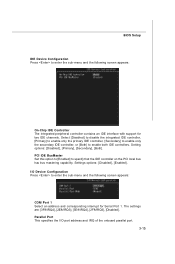
... I /O Device Configuration Press to enter the sub-menu and the following screen appears: On-Chip IDE Controller The integrated peripheral controller contains an IDE interface with support for Serial Port 1. PCI IDE BusMaster Set this option to [Enabled] to enable both IDE controllers. The settings are: [3F8/IRQ4], [2E8/IRQ3], [3E8/IRQ4], [2F8/IRQ3], [Disabled]. BIOS Setup IDE Device Configuration Press to enter the sub-menu and the following screen appears: COM Port 1 Select an address and corresponding interrupt for two IDE channels. Setting options: [Disabled], [Primary...
... I /O Device Configuration Press to enter the sub-menu and the following screen appears: On-Chip IDE Controller The integrated peripheral controller contains an IDE interface with support for Serial Port 1. PCI IDE BusMaster Set this option to [Enabled] to enable both IDE controllers. The settings are: [3F8/IRQ4], [2E8/IRQ3], [3E8/IRQ4], [2F8/IRQ3], [Disabled]. BIOS Setup IDE Device Configuration Press to enter the sub-menu and the following screen appears: COM Port 1 Select an address and corresponding interrupt for two IDE channels. Setting options: [Disabled], [Primary...
User Guide
Page 57
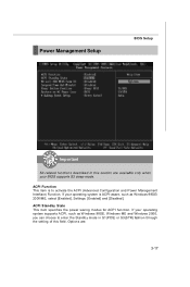
... choose to activate the ACPI (Advanced Configuration and Power Management Interface) Function. Options are available only when your BIOS supports S3 sleep mode. ACPI Standby State This item specifies the power saving modes for ACPI function. If your operating system is to enter the Standby mode in this field. If your operating system supports ACPI, such as Windows 98SE/ 2000/ME, select [Enabled]. Power Management Setup BIOS Setup Important S3-related functions...
... choose to activate the ACPI (Advanced Configuration and Power Management Interface) Function. Options are available only when your BIOS supports S3 sleep mode. ACPI Standby State This item specifies the power saving modes for ACPI function. If your operating system is to enter the Standby mode in this field. If your operating system supports ACPI, such as Windows 98SE/ 2000/ME, select [Enabled]. Power Management Setup BIOS Setup Important S3-related functions...
User Guide
Page 59
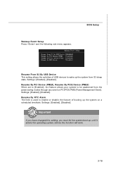
... sleep state. Resume From S3 By USB Device This setting allows the activities of booting up until it enters the operating system, before this function will work. 3-19 Resume By PCI Device (PME#), Resume By PCIE Device (PME#) When set to [Enabled], the feature allows your system to wake up the system from the power saving modes through any event on a scheduled time/date. BIOS Setup Wakeup Event Setup...
... sleep state. Resume From S3 By USB Device This setting allows the activities of booting up until it enters the operating system, before this function will work. 3-19 Resume By PCI Device (PME#), Resume By PCIE Device (PME#) When set to [Enabled], the feature allows your system to wake up the system from the power saving modes through any event on a scheduled time/date. BIOS Setup Wakeup Event Setup...
User Guide
Page 65
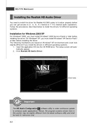
...® XP Service Pack1 or later before installing the driver. Follow the procedures described below to install the drivers for different operating systems. Installation for reference only. The setup screen will automatically appear. 2. A-2 channel or 7.1+2 channel audio operations. Insert the application CD into the CD-ROM drive. Click here Important The HD Audio Configuration software utility is under continuous update to 2-, 4-, 6-, 8- For Windows® XP, you install the drivers in this...
...® XP Service Pack1 or later before installing the driver. Follow the procedures described below to install the drivers for different operating systems. Installation for reference only. The setup screen will automatically appear. 2. A-2 channel or 7.1+2 channel audio operations. Insert the application CD into the CD-ROM drive. Click here Important The HD Audio Configuration software utility is under continuous update to 2-, 4-, 6-, 8- For Windows® XP, you install the drivers in this...

User Guide
Page 90
.... Turn on the monitor and then your graphics card with the slot and press it in a basic video mode. Your monitor will appear once the boot procedure is fully seated. 7. Higher refresh rates are not available at this stage of the computer chassis. Reconnect any cables you have installed the proper drivers and software, you have disconnected and plug in or fasten the graphics card securely and replace...
.... Turn on the monitor and then your graphics card with the slot and press it in a basic video mode. Your monitor will appear once the boot procedure is fully seated. 7. Higher refresh rates are not available at this stage of the computer chassis. Reconnect any cables you have installed the proper drivers and software, you have disconnected and plug in or fasten the graphics card securely and replace...
User Guide
Page 91
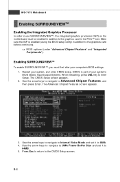
... enter Setup. u BIOS options (under "Advanced Chipset Features" and "Integrated Peripherals"). Restart your computer's BIOS settings. 1. The Advanced Chipset Features screen appears. 3. The CMOS Setup screen appears. 2. B-6 Make sure the IGP is part of your system's BIOS (Basic Input/Output System). CMOS is enabled (using the BIOS setup utility) in addition to the graphics card before continuing. Use the arrow keys to navigate to UMA Frame Buffer Size and set it to the graphics card in the PCIe™ slot. Enabling...
... enter Setup. u BIOS options (under "Advanced Chipset Features" and "Integrated Peripherals"). Restart your computer's BIOS settings. 1. The Advanced Chipset Features screen appears. 3. The CMOS Setup screen appears. 2. B-6 Make sure the IGP is part of your system's BIOS (Basic Input/Output System). CMOS is enabled (using the BIOS setup utility) in addition to the graphics card before continuing. Use the arrow keys to navigate to UMA Frame Buffer Size and set it to the graphics card in the PCIe™ slot. Enabling...
User Guide
Page 93
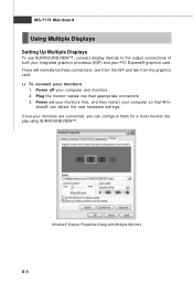
... restart your PCI Express® graphics card. dows® can configure them for a multi-monitor display using SURROUNDVIEW™. MS-7173 Mainboard Using Multiple Displays Setting Up Multiple Displays To use SURROUNDVIEW ™, connect display devices to the output connections of both your integrated graphics processor (IGP) and your computer so that W in- Once your monitors 1. u To connect your monitors are connected, you can detect the new hardware settings. Plug the monitor cables into their appropriate connectors. 3. Windows® Display Properties...
... restart your PCI Express® graphics card. dows® can configure them for a multi-monitor display using SURROUNDVIEW™. MS-7173 Mainboard Using Multiple Displays Setting Up Multiple Displays To use SURROUNDVIEW ™, connect display devices to the output connections of both your integrated graphics processor (IGP) and your computer so that W in- Once your monitors 1. u To connect your monitors are connected, you can detect the new hardware settings. Plug the monitor cables into their appropriate connectors. 3. Windows® Display Properties...

