
User Guide
Page 1
Preface Z87M-G43 H87M-G43 B85M-G43 Motherboard G52-78231X1
Preface Z87M-G43 H87M-G43 B85M-G43 Motherboard G52-78231X1
User Guide
Page 11
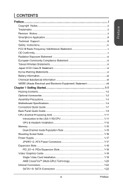
... vi Battery Information vii Chemical Substances Information vii WEEE (Waste Electrical and Electronic Equipment) Statement viii Chapter 1 Getting Started 1-1 Packing Contents 1-2 Optional Accessories 1-2 Assembly Precautions 1-3 Motherboard Specifications 1-4 Connectors Quick Guide 1-7 Back Panel Quick Guide 1-9 CPU (Central Processing Unit 1-11 Introduction to the LGA 1150 CPU 1-11 CPU & Heatsink Installation 1-12 Memory...
... vi Battery Information vii Chemical Substances Information vii WEEE (Waste Electrical and Electronic Equipment) Statement viii Chapter 1 Getting Started 1-1 Packing Contents 1-2 Optional Accessories 1-2 Assembly Precautions 1-3 Motherboard Specifications 1-4 Connectors Quick Guide 1-7 Back Panel Quick Guide 1-9 CPU (Central Processing Unit 1-11 Introduction to the LGA 1150 CPU 1-11 CPU & Heatsink Installation 1-12 Memory...
User Guide
Page 12
...: Parallel Port Connector 1-28 Jumpers 1-29 JBAT1: Clear CMOS Jumper 1-29 Drivers and Utilities 1-30 Total Installer 1-30 Chapter 2 Quick Installation 2-1 CPU Installation 2-2 Memory Installation 2-4 Motherboard Installation 2-5 Power Connectors Installation 2-7 SATA HDD Installation 2-9 mSATA SSD Installation 2-10 Front Panel Connector Installation 2-11 JFP1 Connecotr Installation 2-11 Front Panel Audio Connector Installation...
...: Parallel Port Connector 1-28 Jumpers 1-29 JBAT1: Clear CMOS Jumper 1-29 Drivers and Utilities 1-30 Total Installer 1-30 Chapter 2 Quick Installation 2-1 CPU Installation 2-2 Memory Installation 2-4 Motherboard Installation 2-5 Power Connectors Installation 2-7 SATA HDD Installation 2-9 mSATA SSD Installation 2-10 Front Panel Connector Installation 2-11 JFP1 Connecotr Installation 2-11 Front Panel Audio Connector Installation...

User Guide
Page 15
Designed to fit the advanced Intel® LGA1150 processor, the Z87M-G43/ H87M-G43/ B85M-G43 Series motherboards deliver a high performance and professional desktop platform solution. Chapter 1 Getting Started Thank you for optimal system efficiency. The Z87M-G43/ H87M-G43/ B85M-G43 Series motherboards are based on Intel® Z87/ H87/ B85 chipset for choosing the Z87M-G43/ H87M-G43/ B85M-G43 Series (MS7823 v1.X) Micro-ATX motherboard.
Designed to fit the advanced Intel® LGA1150 processor, the Z87M-G43/ H87M-G43/ B85M-G43 Series motherboards deliver a high performance and professional desktop platform solution. Chapter 1 Getting Started Thank you for optimal system efficiency. The Z87M-G43/ H87M-G43/ B85M-G43 Series motherboards are based on Intel® Z87/ H87/ B85 chipset for choosing the Z87M-G43/ H87M-G43/ B85M-G43 Series (MS7823 v1.X) Micro-ATX motherboard.

User Guide
Page 16
Chapter 1 Packing Contents Motherboard Drivers & Utilities Disc Motherboard User Guide I/O Shield SATA Cable Optional Accessories USB 3.0 Bracket M-Connector * These pictures are for reference only and may vary without notice. * The packing contents may vary according to the model you purchased. * If you need to purchase the optional accessories or request part numbers, please visit the MSI website at http://www.msi.com/index.php or consult the dealer. Getting Started 1-2
Chapter 1 Packing Contents Motherboard Drivers & Utilities Disc Motherboard User Guide I/O Shield SATA Cable Optional Accessories USB 3.0 Bracket M-Connector * These pictures are for reference only and may vary without notice. * The packing contents may vary according to the model you purchased. * If you need to purchase the optional accessories or request part numbers, please visit the MSI website at http://www.msi.com/index.php or consult the dealer. Getting Started 1-2

User Guide
Page 17
...■ If you need help during any computer component. ■ Ensure that there are no loose screws or metal components on the motherboard or anywhere within the computer case. ■ Do not use the computer in this package are securely connected. If an ESD wrist...by the edges to avoid touching sensitive components. ■ It is recommended to wear an electrostatic discharge (ESD) wrist strap when handling the motherboard to damage from the power outlet before installation is completed. Assembly Precautions ■ The components included in a high-temperature environment. ■...
...■ If you need help during any computer component. ■ Ensure that there are no loose screws or metal components on the motherboard or anywhere within the computer case. ■ Do not use the computer in this package are securely connected. If an ESD wrist...by the edges to avoid touching sensitive components. ■ It is recommended to wear an electrostatic discharge (ESD) wrist strap when handling the motherboard to damage from the power outlet before installation is completed. Assembly Precautions ■ The components included in a high-temperature environment. ■...

User Guide
Page 18
... the internal USB connectors) - 10x USB 2.0 ports (4 ports on the back panel, 6 ports available through the internal USB connectors) (for Z87M-G43/ H87MG43) - 8x USB 2.0 ports (4 ports on the back panel, 4 ports available through the internal USB connectors) (for LGA 1150..., supporting a maximum resolution of 4096x2160@24Hz, 24bpp/ 3840x2160@60Hz, 24bpp ■ Supports AMD CrossFireTM Technology ■ Z87M-G43/ H87M-G43 - Chapter 1 Motherboard Specifications CPU Support Chipset Memory Support Expansion Slots Onboard Graphics Multi-GPU Support Storage USB ■ 4th Generation Intel®...
... the internal USB connectors) - 10x USB 2.0 ports (4 ports on the back panel, 6 ports available through the internal USB connectors) (for Z87M-G43/ H87MG43) - 8x USB 2.0 ports (4 ports on the back panel, 4 ports available through the internal USB connectors) (for LGA 1150..., supporting a maximum resolution of 4096x2160@24Hz, 24bpp/ 3840x2160@60Hz, 24bpp ■ Supports AMD CrossFireTM Technology ■ Z87M-G43/ H87M-G43 - Chapter 1 Motherboard Specifications CPU Support Chipset Memory Support Expansion Slots Onboard Graphics Multi-GPU Support Storage USB ■ 4th Generation Intel®...

User Guide
Page 25
...the heatsink to overclock, please make sure the cooling fans work properly to assist in correctly lining up the CPU for motherboard placement. Any attempt to operate beyond product specifications. 1-11 Getting Started The golden triangle is the Pin 1 indicator Important Overheating... Overheating can tolerate overclocking. MSI does not guarantee the damages or risks caused by inadequate operation beyond product specifications is designed to ensure the safety of ...
...the heatsink to overclock, please make sure the cooling fans work properly to assist in correctly lining up the CPU for motherboard placement. Any attempt to operate beyond product specifications. 1-11 Getting Started The golden triangle is the Pin 1 indicator Important Overheating... Overheating can tolerate overclocking. MSI does not guarantee the damages or risks caused by inadequate operation beyond product specifications is designed to ensure the safety of ...

User Guide
Page 26
... remember to ensure correct CPU and heatsink installation. at the address below to install a CPU heatsink. Wrong installation can damage both the CPU and the motherboard. http://youtu.be/bf5La099urI 1. Load lever Retention tab Load plate Important Do not touch the socket contacts or the bottom of the CPU. Follow the...
... remember to ensure correct CPU and heatsink installation. at the address below to install a CPU heatsink. Wrong installation can damage both the CPU and the motherboard. http://youtu.be/bf5La099urI 1. Load lever Retention tab Load plate Important Do not touch the socket contacts or the bottom of the CPU. Follow the...

User Guide
Page 28
...socket pins by covering the socket with the fan's cable facing towards the fan connector and the fasteners matching the holes on the motherboard. 8. Press the four fasteners down the heatsink until the four fasteners get wedged into position a click should be heard. 10. ...• If you purchased a separate CPU and heatsink/ cooler, Please refer to the CPU fan connector on the motherboard. Inspect the motherboard to fasten the heatsink. Motherboard Fastener-end Important • Confirm that the fastener-ends have been properly locked in the heatsink/ cooler package for more...
...socket pins by covering the socket with the fan's cable facing towards the fan connector and the fasteners matching the holes on the motherboard. 8. Press the four fasteners down the heatsink until the four fasteners get wedged into position a click should be heard. 10. ...• If you purchased a separate CPU and heatsink/ cooler, Please refer to the CPU fan connector on the motherboard. Inspect the motherboard to fasten the heatsink. Motherboard Fastener-end Important • Confirm that the fastener-ends have been properly locked in the heatsink/ cooler package for more...

User Guide
Page 30
...that came with the computer case, please replace it with the I /O backplate should be facing toward the rear of the motherboard. Getting Started 1-16 Chapter 1 Important • Install the motherboard on a flat surface free from unnecessary debris. • To prevent damage to the manual that may cause a short ...circuit of the computer case. They should line up with the screw holes on the motherboard are no loose metal components on the I /O ports should snap easily into the computer case without the need for any contact between the...
...that came with the computer case, please replace it with the I /O backplate should be facing toward the rear of the motherboard. Getting Started 1-16 Chapter 1 Important • Install the motherboard on a flat surface free from unnecessary debris. • To prevent damage to the manual that may cause a short ...circuit of the computer case. They should line up with the screw holes on the motherboard are no loose metal components on the I /O ports should snap easily into the computer case without the need for any contact between the...

User Guide
Page 31
..., align the power supply cable with the connector and firmly press the cable into the connector. If done correctly, the clip on the motherboard's power connector. 2.G1.rGouronudnd JPWR2 4.+31.+21V2V 1.+23.+3.33.G4V.3.r+5Vo.5uG6Vn.r7+do.5uG8Vn.rP9do.Wu51nV0R1d.S1+O1B.1+K2211.V+3213.V+4.133...JGVProWunRd 1 Important Make sure that all the power cables are securely connected to a proper ATX power supply to ensure stable operation of the motherboard. 1-17 Getting Started http://youtu.be hooked on the power cable should be /gkDYyR_83I4 JPWR1~2: ATX Power Connectors These connectors allow you ...
..., align the power supply cable with the connector and firmly press the cable into the connector. If done correctly, the clip on the motherboard's power connector. 2.G1.rGouronudnd JPWR2 4.+31.+21V2V 1.+23.+3.33.G4V.3.r+5Vo.5uG6Vn.r7+do.5uG8Vn.rP9do.Wu51nV0R1d.S1+O1B.1+K2211.V+3213.V+4.133...JGVProWunRd 1 Important Make sure that all the power cables are securely connected to a proper ATX power supply to ensure stable operation of the motherboard. 1-17 Getting Started http://youtu.be hooked on the power cable should be /gkDYyR_83I4 JPWR1~2: ATX Power Connectors These connectors allow you ...

User Guide
Page 32
Getting Started 1-18 Read the expansion card's documentation to check for expansion cards, such as discrete graphics or audio cards. Chapter 1 Expansion Slots This motherboard contains numerous slots for any necessary additional hardware or software changes. PCIe 3.0 x16 Slot PCIe 2.0 x16 Slot PCIe 2.0 x1 Slot Important When adding or removing expansion cards, always turn off the power supply and unplug the power supply power cable from the power outlet. PCI_E1~4: PCIe Expansion Slots The PCIe slot supports the PCIe interface expansion card.
Getting Started 1-18 Read the expansion card's documentation to check for expansion cards, such as discrete graphics or audio cards. Chapter 1 Expansion Slots This motherboard contains numerous slots for any necessary additional hardware or software changes. PCIe 3.0 x16 Slot PCIe 2.0 x16 Slot PCIe 2.0 x1 Slot Important When adding or removing expansion cards, always turn off the power supply and unplug the power supply power cable from the power outlet. PCI_E1~4: PCIe Expansion Slots The PCIe slot supports the PCIe interface expansion card.

User Guide
Page 33
For best compatibility, MSI graphics cards are recommended. Video Demonstration Watch the video to learn how to the computer case. Depending on the expansion slot(s) used, there should be ... its expansion slot(s). Some video cards might require a power cable directly from the computer case. 2. Determine what type of the motherboard's expansion slots. Chapter 1 Video/ Graphics Cards If available, this motherboard takes advantage of the CPU's integrate graphics processor, but discrete video cards can be installed by way of expansion slot(s) the...
For best compatibility, MSI graphics cards are recommended. Video Demonstration Watch the video to learn how to the computer case. Depending on the expansion slot(s) used, there should be ... its expansion slot(s). Some video cards might require a power cable directly from the computer case. 2. Determine what type of the motherboard's expansion slots. Chapter 1 Video/ Graphics Cards If available, this motherboard takes advantage of the CPU's integrate graphics processor, but discrete video cards can be installed by way of expansion slot(s) the...

User Guide
Page 34
... on each of the cards by way of the same brand and specifications. For best compatibility with the motherboard, MSI graphics cards are of the metal contacts (please refer to ensure stable operation. This motherboard will work. All displays should be connected to ensure a successful two-way CrossFire™ installation. 1. By linking together...
... on each of the cards by way of the same brand and specifications. For best compatibility with the motherboard, MSI graphics cards are of the metal contacts (please refer to ensure stable operation. This motherboard will work. All displays should be connected to ensure a successful two-way CrossFire™ installation. 1. By linking together...

User Guide
Page 36
...This connector is recommended that large SATA devices, such as HDDs, SSDs, and optical drives, be /RZsMpqxythc Chapter 1 SATA2 SATA1 SATA4 SATA6 SATA3 SATA5 For Z87M-G43/ H87M-G43 - SATA5, SATA6 (3Gb/s, by Intel® B85) - Such devices include disk drives (HDD), solid state drives (SSD), and optical... (SSD), and optical drives (CD/ DVD/ Blu-Ray). Getting Started 1-22 http://youtu.be screwed down into the case. Please refer to the motherboard for space saving purposes. SATA1~6 (6Gb/s, by Intel® Z87/ H87) For B85M-G43 - Each connector can connect to Install SATA HDD....
...This connector is recommended that large SATA devices, such as HDDs, SSDs, and optical drives, be /RZsMpqxythc Chapter 1 SATA2 SATA1 SATA4 SATA6 SATA3 SATA5 For Z87M-G43/ H87M-G43 - SATA5, SATA6 (3Gb/s, by Intel® B85) - Such devices include disk drives (HDD), solid state drives (SSD), and optical... (SSD), and optical drives (CD/ DVD/ Blu-Ray). Getting Started 1-22 http://youtu.be screwed down into the case. Please refer to the motherboard for space saving purposes. SATA1~6 (6Gb/s, by Intel® Z87/ H87) For B85M-G43 - Each connector can connect to Install SATA HDD....

User Guide
Page 37
... to connect all system fans, adapters are available to connect a fan directly to take advantage of the CPU fan control. If the motherboard has a System Hardware Monitor chipset on the motherboard to connect all system fans. Remember to find recommended CPU heatsink. • These connectors support Smart Fan Control with +12V. A system... Chapter 1 CPUFAN1,SYSFAN1~2: Fan Power Connectors The fan power connectors support system cooling fans with liner mode. Some system fans may not connect to the motherboard and will instead connect to the power supply directly.
... to connect all system fans, adapters are available to connect a fan directly to take advantage of the CPU fan control. If the motherboard has a System Hardware Monitor chipset on the motherboard to connect all system fans. Remember to find recommended CPU heatsink. • These connectors support Smart Fan Control with +12V. A system... Chapter 1 CPUFAN1,SYSFAN1~2: Fan Power Connectors The fan power connectors support system cooling fans with liner mode. Some system fans may not connect to the motherboard and will instead connect to the power supply directly.

User Guide
Page 38
...; Front Panel I/O Connectivity Design Guide. Video Demonstration Watch the video to learn how to simplify installation. Getting Started 1-24 http://youtu.be plugged into the motherboard. Please use the optional M-Connector to Install front panel connectors. Plug all the wires from the case, pins marked by small triangles are positive wires...
...; Front Panel I/O Connectivity Design Guide. Video Demonstration Watch the video to learn how to simplify installation. Getting Started 1-24 http://youtu.be plugged into the motherboard. Please use the optional M-Connector to Install front panel connectors. Plug all the wires from the case, pins marked by small triangles are positive wires...
User Guide
Page 39
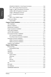
... that don't disconnect the device when you charge it in S1 state. 1-25 Getting Started When the SuperCharger application is turned on select MSI motherboard models. When the computer is in S3, S4, S5 state. • We recommend that the VCC and GND pins must be enabled... as a normal USB 2.0 connector, please turn off the SuperCharger application. The JUSB1 (red mark) connector supports MSI's new SuperCharger technology which provides quicker USB charging of your motherboard has SuperCharger technology. • For iPad, JUSB1 (red mark) can still charge iPad in stand-by or ...
... that don't disconnect the device when you charge it in S1 state. 1-25 Getting Started When the SuperCharger application is turned on select MSI motherboard models. When the computer is in S3, S4, S5 state. • We recommend that the VCC and GND pins must be enabled... as a normal USB 2.0 connector, please turn off the SuperCharger application. The JUSB1 (red mark) connector supports MSI's new SuperCharger technology which provides quicker USB charging of your motherboard has SuperCharger technology. • For iPad, JUSB1 (red mark) can still charge iPad in stand-by or ...

User Guide
Page 43
... clear the CMOS RAM. 1 Keep Data 1 Clear Data Important You can automatically boot into the operating system (OS) every time it will damage the motherboard. Jumpers JBAT1: Clear CMOS Jumper There is CMOS RAM onboard that is on because it is off. With the CMOS RAM, the system can clear ...
... clear the CMOS RAM. 1 Keep Data 1 Clear Data Important You can automatically boot into the operating system (OS) every time it will damage the motherboard. Jumpers JBAT1: Clear CMOS Jumper There is CMOS RAM onboard that is on because it is off. With the CMOS RAM, the system can clear ...


