User Guide
Page 3
... technical guide, BIOS updates, driver updates, and other information: http://www.msi.com/service/download Contact our technical staff at 110/220V before connecting the equipment to the power inlet. ■ Place the power cord such a way that can cause damage or cause electrical shock. &#...65517; If any liquid into the opening that people can not get the equipment checked by service personnel: ◯ The power cord or plug is at : http://support.msi.com Safety Instructions ■ Always read the safety instructions carefully. ■ Keep this User's Manual for future reference....
... technical guide, BIOS updates, driver updates, and other information: http://www.msi.com/service/download Contact our technical staff at 110/220V before connecting the equipment to the power inlet. ■ Place the power cord such a way that can cause damage or cause electrical shock. &#...65517; If any liquid into the opening that people can not get the equipment checked by service personnel: ◯ The power cord or plug is at : http://support.msi.com Safety Instructions ■ Always read the safety instructions carefully. ■ Keep this User's Manual for future reference....
User Guide
Page 4
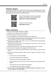
power cord, if any, must accept any interference received, including interference that may cause harmful interference to radio communications. Wireless Radio Use This device is subject ...
power cord, if any, must accept any interference received, including interference that may cause harmful interference to radio communications. Wireless Radio Use This device is subject ...
User Guide
Page 10
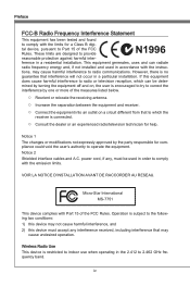
... Started 1-1 Packing Contents 1-2 Optional Accessories 1-2 Assembly Precautions 1-3 Mainboard Specifications 1-4 Connectors Quick Guide 1-6 Back Panel Quick Guide 1-8 CPU (Central Processing Unit 1-10 Mounting Screw Holes 1-14 Power Supply 1-15 Memory 1-16 Expansion Slots 1-18 Video/ Graphics Cards 1-19 Internal Connectors 1-24 Buttons 1-32 Jumpers 1-34 Switch 1-35 LED Status Indicators 1-36 Drivers...
... Started 1-1 Packing Contents 1-2 Optional Accessories 1-2 Assembly Precautions 1-3 Mainboard Specifications 1-4 Connectors Quick Guide 1-6 Back Panel Quick Guide 1-8 CPU (Central Processing Unit 1-10 Mounting Screw Holes 1-14 Power Supply 1-15 Memory 1-16 Expansion Slots 1-18 Video/ Graphics Cards 1-19 Internal Connectors 1-24 Buttons 1-32 Jumpers 1-34 Switch 1-35 LED Status Indicators 1-36 Drivers...
User Guide
Page 14
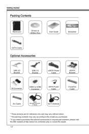
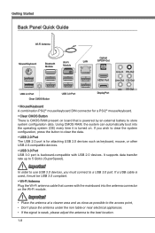
... Packing Contents Mainboard Drivers & Utilities Disc User Guide Backplate SATA Cable Optional Accessories USB 2.0 Bracket USB 3.0 Bracket eSATA Power Cable eSATA Bracket M-Connector USB3 to USB2 Connector SATA Power Cable CrossFire Cable SLI Cable MSI MultiConnect Panel Wi-Fi Antenna * These pictures are for reference only and may vary without notice. * The packing...
... Packing Contents Mainboard Drivers & Utilities Disc User Guide Backplate SATA Cable Optional Accessories USB 2.0 Bracket USB 3.0 Bracket eSATA Power Cable eSATA Bracket M-Connector USB3 to USB2 Connector SATA Power Cable CrossFire Cable SLI Cable MSI MultiConnect Panel Wi-Fi Antenna * These pictures are for reference only and may vary without notice. * The packing...
User Guide
Page 15
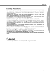
... 1-3 Chapter 1 MS-7751 Assembly Precautions ■ The components included in this package are prone to damage from the power outlet before installation is recommended to wear an electrostatic discharge (ESD) wrist strap when handling the mainboard to prevent electrostatic damage. ... yourself of static electricity by the edges to ensure successful computer assembly. ■ Always turn off the power supply and unplug the power cord from electrostatic discharge (ESD). Please adhere to the following instructions to avoid touching sensitive components. ■ It...
... 1-3 Chapter 1 MS-7751 Assembly Precautions ■ The components included in this package are prone to damage from the power outlet before installation is recommended to wear an electrostatic discharge (ESD) wrist strap when handling the mainboard to prevent electrostatic damage. ... yourself of static electricity by the edges to ensure successful computer assembly. ■ Always turn off the power supply and unplug the power cord from electrostatic discharge (ESD). Please adhere to the following instructions to avoid touching sensitive components. ■ It...
User Guide
Page 17
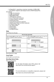
... Debug LED panel - 1x Voice Genie connector (optional) - 1x MultiConnect Panel connector (optional) - 1x V-Check Points Set - 1x OC Genie button - 1x Reset button - 1x Power button - 1x GO2BIOS button Slots ■ 3x PCIe 3.0 x16 slots PCIe x16 slots support table When installing 3rd Gen Intel® Core™ i7/ Core... Form Factor ■ ATX (30.5 cm X 24.5 cm) Mounting Screw Holes ■ 9x mounting holes For the latest information about CPU, please visit http://www.msi.com/service/cpu-support For more information on compatible components, please visit http://www...
... Debug LED panel - 1x Voice Genie connector (optional) - 1x MultiConnect Panel connector (optional) - 1x V-Check Points Set - 1x OC Genie button - 1x Reset button - 1x Power button - 1x GO2BIOS button Slots ■ 3x PCIe 3.0 x16 slots PCIe x16 slots support table When installing 3rd Gen Intel® Core™ i7/ Core... Form Factor ■ ATX (30.5 cm X 24.5 cm) Mounting Screw Holes ■ 9x mounting holes For the latest information about CPU, please visit http://www.msi.com/service/cpu-support For more information on compatible components, please visit http://www...
User Guide
Page 19
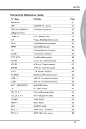
... Intrusion Connector JDLED3 Voice Genie Connector JFP1, JFP2 Front Panel Connectors JPWR1 ATX 24-pin Power Connector JPWR2 ATX 8-pin Power Connector JPWR3 ATX 6-pin Power Connector JTPM1 TPM Module connector JTURBO1 MultiConnect Panel Connector JUSB1~3 USB 2.0 Expansion Connectors JUSB4 ...SWITCH Multi-BIOS Switch OC1 OC Genie Button PCI_E2, 5, 7 PCIe x16 Expansion Slots PCI_E1, 3, 4, 6 PCIe x1 Expansion Slots POWER1 Power Button RESET1 Reset Button SW1 GO2BIOS Button SATA1~2 SATA 6Gb/s Connectors SATA3~6 SATA 3Gb/s Connectors MS-7751 Page 1-8 1-10 1-25 1-37...
... Intrusion Connector JDLED3 Voice Genie Connector JFP1, JFP2 Front Panel Connectors JPWR1 ATX 24-pin Power Connector JPWR2 ATX 8-pin Power Connector JPWR3 ATX 6-pin Power Connector JTPM1 TPM Module connector JTURBO1 MultiConnect Panel Connector JUSB1~3 USB 2.0 Expansion Connectors JUSB4 ...SWITCH Multi-BIOS Switch OC1 OC Genie Button PCI_E2, 5, 7 PCIe x16 Expansion Slots PCI_E1, 3, 4, 6 PCIe x1 Expansion Slots POWER1 Power Button RESET1 Reset Button SW1 GO2BIOS Button SATA1~2 SATA 6Gb/s Connectors SATA3~6 SATA 3Gb/s Connectors MS-7751 Page 1-8 1-10 1-25 1-37...
User Guide
Page 20
... such as possible to the access point, • Don't place the antenna under the iron table or near electrical appliances. • If the signal is powered by an external battery to store system configuration data. Using CMOS RAM, the system can automatically boot into the antenna connector on . If you must...
... such as possible to the access point, • Don't place the antenna under the iron table or near electrical appliances. • If the signal is powered by an external battery to store system configuration data. Using CMOS RAM, the system can automatically boot into the antenna connector on . If you must...
User Guide
Page 22
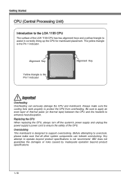
...heatsink to enhance heat dissipation. Alignment Key Yellow triangle is designed to assist in correctly lining up the CPU for mainboard placement. MSI does not guarantee the damages or risks caused by inadequate operation beyond product specifications is the Pin 1 indicator. Be sure to apply...attempt to ensure the safety of the CPU. Replacing the CPU When replacing the CPU, always turn off the system's power supply and unplug the power supply's power cord to operate beyond product specifications. 1-10 Always make sure that all other system components can seriously damage the CPU ...
...heatsink to enhance heat dissipation. Alignment Key Yellow triangle is designed to assist in correctly lining up the CPU for mainboard placement. MSI does not guarantee the damages or risks caused by inadequate operation beyond product specifications is the Pin 1 indicator. Be sure to apply...attempt to ensure the safety of the CPU. Replacing the CPU When replacing the CPU, always turn off the system's power supply and unplug the power supply's power cord to operate beyond product specifications. 1-10 Always make sure that all other system components can seriously damage the CPU ...
User Guide
Page 27
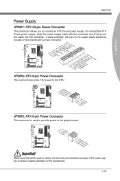
....eu+2ds2n5.+3dV2.5+4V5.GVround JPWR2: ATX 8-pin Power Connector This connector provides 12V power to the CPU. 1.G2.rG3o.urG4on.urdGonurdonudnd 5.+61.+721.V+821.V+21V2V JPWR3: ATX 6-pin Power Connector This connector is used to provide power to ensure stable operation of the mainboard. 1-15 ...To connect the ATX 24-pin power supply, align the power supply cable with the connector and firmly press the cable into...
....eu+2ds2n5.+3dV2.5+4V5.GVround JPWR2: ATX 8-pin Power Connector This connector provides 12V power to the CPU. 1.G2.rG3o.urG4on.urdGonurdonudnd 5.+61.+721.V+821.V+21V2V JPWR3: ATX 6-pin Power Connector This connector is used to provide power to ensure stable operation of the mainboard. 1-15 ...To connect the ATX 24-pin power supply, align the power supply cable with the connector and firmly press the cable into...
User Guide
Page 30
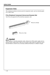
PCIe (Peripheral Component Interconnect Express) Slot The PCIe slot supports the PCIe interface expansion card. Read the expansion card's documentation to check for expansion cards, such as discrete graphics or audio cards. Getting Started Expansion Slots This mainboard contains numerous ports for any necessary additional hardware or software changes. 1-18 PCIe 3.0 x16 Slot PCIe 2.0 x1 Slot Important When adding or removing expansion cards, always turn off the power supply and unplug the power supply power cable from the power outlet.
PCIe (Peripheral Component Interconnect Express) Slot The PCIe slot supports the PCIe interface expansion card. Read the expansion card's documentation to check for expansion cards, such as discrete graphics or audio cards. Getting Started Expansion Slots This mainboard contains numerous ports for any necessary additional hardware or software changes. 1-18 PCIe 3.0 x16 Slot PCIe 2.0 x1 Slot Important When adding or removing expansion cards, always turn off the power supply and unplug the power supply power cable from the power outlet.
User Guide
Page 31
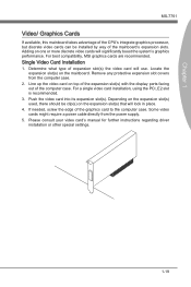
For best compatibility, MSI graphics cards are recommended. Determine what type of expansion slot(s) the video card will significantly boost the system's graphics performance. Push the video card into ... the mainboard. Single Video Card Installation 1. For a single video card installation, using the PCI_E2 slot is recommended. 3. Remove any protective expansion slot covers from the power supply. 5. Chapter 1 MS-7751 Video/ Graphics Cards If available, this mainboard takes advantage of the CPU's integrate graphics processor, but discrete video cards can be...
For best compatibility, MSI graphics cards are recommended. Determine what type of expansion slot(s) the video card will significantly boost the system's graphics performance. Push the video card into ... the mainboard. Single Video Card Installation 1. For a single video card installation, using the PCI_E2 slot is recommended. 3. Remove any protective expansion slot covers from the power supply. 5. Chapter 1 MS-7751 Video/ Graphics Cards If available, this mainboard takes advantage of the CPU's integrate graphics processor, but discrete video cards can be...
User Guide
Page 32
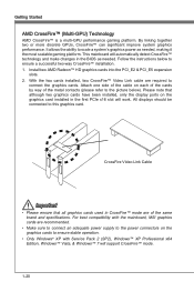
...the cards by way of the metal contacts (please refer to ensure stable operation. • Only Windows® XP with the mainboard, MSI graphics cards are of the same brand and specifications. For best compatibility with Service Pack 2 (SP2), Windows™ XP Professional x64 ...or more discrete GPUs, CrossFire™ can significant improve system graphics performance. All displays should be connected to scale a system's graphics power as needed , making it the most scalable gaming platform. CrossFire Video Link Cable Important • Please ensure that although two graphics cards...
...the cards by way of the metal contacts (please refer to ensure stable operation. • Only Windows® XP with the mainboard, MSI graphics cards are of the same brand and specifications. For best compatibility with Service Pack 2 (SP2), Windows™ XP Professional x64 ...or more discrete GPUs, CrossFire™ can significant improve system graphics performance. All displays should be connected to scale a system's graphics power as needed , making it the most scalable gaming platform. CrossFire Video Link Cable Important • Please ensure that although two graphics cards...
User Guide
Page 35
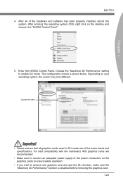
...system (OS), right click on your operating system, the screen may look different. Enter the NVIDIA Control Panel. For best compatibility with the mainboard, MSI graphics cards are of the hardware and software has been properly installed, reboot the system. Choose this item Important • Please ensure that all ..."NVIDIA Control Panel". 5. Chapter 1 MS-7751 4. After all graphics cards used in SLI mode are recommended. • Make sure to connect an adequate power supply to the power connectors on the graphics cards to ensure stable operation. • If you wish to enable SLI mode.
...system (OS), right click on your operating system, the screen may look different. Enter the NVIDIA Control Panel. For best compatibility with the mainboard, MSI graphics cards are of the hardware and software has been properly installed, reboot the system. Choose this item Important • Please ensure that all ..."NVIDIA Control Panel". 5. Chapter 1 MS-7751 4. After all graphics cards used in SLI mode are recommended. • Make sure to connect an adequate power supply to the power connectors on the graphics cards to ensure stable operation. • If you wish to enable SLI mode.
User Guide
Page 36
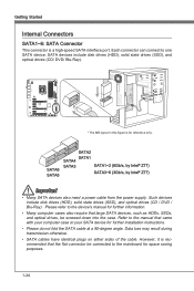
... optical drives (CD / DVD / Blu-Ray). SATA6 SATA5 SATA2 SATA1 SATA4 SATA3 SATA1~2 (6Gb/s, by Intel® Z77) SATA3~6 (3Gb/s, by Intel® Z77) Important • Many SATA devices also need a power cable from the power supply. Refer to the mainboard for further information. • Many computer cases also require that came with your...
... optical drives (CD / DVD / Blu-Ray). SATA6 SATA5 SATA2 SATA1 SATA4 SATA3 SATA1~2 (6Gb/s, by Intel® Z77) SATA3~6 (3Gb/s, by Intel® Z77) Important • Many SATA devices also need a power cable from the power supply. Refer to the mainboard for further information. • Many computer cases also require that came with your...
User Guide
Page 37
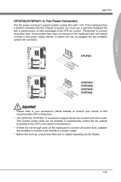
... chipset on the mainboard to connect all system fans. Remember to connect all system fans, adapters are available to connect a fan directly to a power supply. • Before first boot up, ensure that there are not enough ports on -board, you must use a specially designed fan with ...+12V. A system fan can be plugged into any fan blades. 1-25 Chapter 1 MS-7751 CPUFAN,SYSFAN1~4: Fan Power Connectors The fan power connectors support system cooling fans with a speed sensor to take advantage of the CPU fan control. CPUFAN 4.3C.oS2n.e+1tnr.1osG2lorVround 4.3N...
... chipset on the mainboard to connect all system fans. Remember to connect all system fans, adapters are available to connect a fan directly to a power supply. • Before first boot up, ensure that there are not enough ports on -board, you must use a specially designed fan with ...+12V. A system fan can be plugged into any fan blades. 1-25 Chapter 1 MS-7751 CPUFAN,SYSFAN1~4: Fan Power Connectors The fan power connectors support system cooling fans with a speed sensor to take advantage of the CPU fan control. CPUFAN 4.3C.oS2n.e+1tnr.1osG2lorVround 4.3N...
User Guide
Page 39
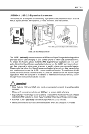
...• SuperCharger Technology is only available on select MSI mainboard models. When the SuperCharger application is turned on, the JUSB1 connector will convert data channels to extra power channels to check if your cellular phone or other USB-powered devices. To enable this figure is for reference ...only. Please refer to the MSI website to quickly charge your computer. Chapter 1 115V MS-7751 ...
...• SuperCharger Technology is only available on select MSI mainboard models. When the SuperCharger application is turned on, the JUSB1 connector will convert data channels to extra power channels to check if your cellular phone or other USB-powered devices. To enable this figure is for reference ...only. Please refer to the MSI website to quickly charge your computer. Chapter 1 115V MS-7751 ...
User Guide
Page 44
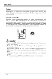
Press this button once while the system is possible to disable the OC Genie function in the BIOS setup. To disable OC Genie, power off to normal values. Getting Started Buttons The mainboard has numerous on-board buttons to automatically overclock the system. OC1: OC Genie ...use the OC Genie function. • We do not guarantee the OC Genie overclocking range or the damages/risks caused by MSI. • To ensure successfully OC Genie usage, MSI components are recommended. 1-32 The button will explain how to optimal performance values. Important • Please install DDR3 1333 ...
Press this button once while the system is possible to disable the OC Genie function in the BIOS setup. To disable OC Genie, power off to normal values. Getting Started Buttons The mainboard has numerous on-board buttons to automatically overclock the system. OC1: OC Genie ...use the OC Genie function. • We do not guarantee the OC Genie overclocking range or the damages/risks caused by MSI. • To ensure successfully OC Genie usage, MSI components are recommended. 1-32 The button will explain how to optimal performance values. Important • Please install DDR3 1333 ...
User Guide
Page 45
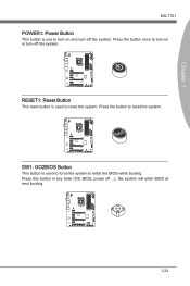
RESET1: Reset Button This reset button is used to force the system to enter the BIOS while booting. SW1: GO2BIOS Button This button is used to reset the system. Chapter 1 MS-7751 POWER1: Power Button This button is use to turn-on or turn -off the system. Press this button in any state (OS, BIOS, power off the system. Press the button to turn-on and turn -off ...), the system will enter BIOS at next booting. 1-33 Press the button once to reset the system.
RESET1: Reset Button This reset button is used to force the system to enter the BIOS while booting. SW1: GO2BIOS Button This button is used to reset the system. Chapter 1 MS-7751 POWER1: Power Button This button is use to turn-on or turn -off the system. Press this button in any state (OS, BIOS, power off the system. Press the button to turn-on and turn -off ...), the system will enter BIOS at next booting. 1-33 Press the button once to reset the system.
User Guide
Page 46
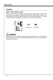
... system configuration, set the jumpers to save system configuration data. Getting Started Jumpers JBAT1: Clear CMOS Jumper There is CMOS RAM onboard that is external powered from a battery located on the mainboard to clear the CMOS RAM. 1 Keep Data 1 Clear Data Important You can automatically boot into the operating system (OS...
... system configuration, set the jumpers to save system configuration data. Getting Started Jumpers JBAT1: Clear CMOS Jumper There is CMOS RAM onboard that is external powered from a battery located on the mainboard to clear the CMOS RAM. 1 Keep Data 1 Clear Data Important You can automatically boot into the operating system (OS...


