MSI P45 NEO-F Support Question
MSI P45 NEO-F Support Question
Find answers below for this question about MSI P45 NEO-F - Motherboard - ATX.Need a MSI P45 NEO-F manual? We have 1 online manual for this item!
Question posted by ianatheight on November 7th, 2012
Forgot The Combination Of Wires Of The Power Socket
I got the combinations for wires which were fixed into the power socket of msi motherboard ms 7528 version 1.1, and now i am unalble fix them....so please help me...
I had attached the picture of the motheboard...
Supporting Image
You can click the image below to enlarge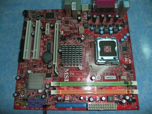
Current Answers
Related MSI P45 NEO-F Manual Pages
User Guide - Page 3
... 600 C (1400F), IT MAYDAMAGE THE EQUIPMENT. Safety Instructions
1.
Do not place
anything over the power cord. 8. If any of breakage. 12. Keep this equipment on a reliable flat surface before inserting... Make sure the voltage of expl os i on the enclosure are for future reference. 3. Place the power cord such a way that could damage or cause electrical
s h oc k . 11. Never pour...
User Guide - Page 4
... user's authority to operate the equipment. Micro-Star International MS-7519
This device complies with the limits for a Class ... comply with the instructions, may cause undesired operation. power cord, if any interference received, including interference that
...designed to correct the interference by the party responsible for help. Notice 2 Shielded interface cables and A.C. VOIR LANOTICE...
User Guide - Page 8

... ...2-10 Connectors ...2-12 Jumpers ...2-19 Slots ...2-20 Chapter 3 BIOS Setup 3-1 Entering Setup ...3-2 The Main Menu ...3-4 Standard CMOS Features 3-6 Advanced BIOS Features 3-9 Integrated Peripherals 3-13 Power Management Setup 3-15 H/W Monitor ...3-18 BIOS Setting Password 3-19 Cell Menu ...3-20 Load Fail-Safe/ Optimized Defaults 3-24 Appendix A Realtek ALC888 Audio A-1 Installing the...
User Guide - Page 11

...Core 2 Extreme, Core 2 Quad, Core 2 Duo, Pentium Dual-Core and Celeron Dual-Core LGA775 processor, the P45 Neo/ G45 Neo/ P43 Neo Series deliver a high performance and professional desktop platform solution.
1-1 The P45 Neo/ G45 Neo/ P43 Neo Series mainboards are based on Intel® P45/ G45/ P43 & ICH10 chipsets for choosing the P45 Neo/ G45 Neo/ P43 Neo Series (MS-7519 v1.X) ATX mainboard.
User Guide - Page 14

MS-7519 Mainboard
Mainboard Layout
JPWR 1
IDE 1
Top : mouse Bottom: keyboard
JPWR2
Parallel port Bottom:
COM port VGA port(for G45)
SYSFAN1 ...SATA2 SATA4
ALC888
PCI 2 PCI 3
JMicron JMB381 (optional)
JBAT1
BATT +
JUSB4 JUSB3 JUSB2
JAUD1 JCD1 JSP1
FDD 1
JTPM1 (optional )
JFP2
JFP1
P45 Neo/ G45 Neo/ P43 Neo Series (MS-7519 v1.X) ATX Mainboard
1-4
SATA1 SATA3
JCI1 SATA5
SATA6
JUSB1
User Guide - Page 15
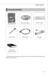
Packing Checklist
Getting Started
MSI motherboard
MSI Driver/Utility CD
Back IO Shield
Power Cable
SATA Cable
IDE Cable
User's Guide and Quick Guide
* The pictures are for reference only and may vary from the packing contents of the product you purchased.
1-5
User Guide - Page 19
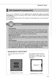
...and the heatsink to support overclocking.
For the latest information about CPU, please visit http://global.msi.com.tw/index.php? Overclocking This mainboard is the Pin 1 indicator
2-3 Make sure that you...the CPU, always turn off the ATX power supply or unplug the power supply's power cord from overheating. Any attempt to tolerate such abnormal setting, while doing overclocking.
User Guide - Page 20
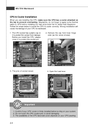
... the socket pin.
2. Follow the steps below to avoid damaging. 3.
MS-7519 Mainboard...
CPU & Cooler Installation
W hen you install the CPU, always cover it to protect the contact from lever hinge side (as the arrow shows).
3. Before you are installing the CPU, make sure the CPU has a cooler attached on the top to prevent overheating. Do not touch the CPU socket...
User Guide - Page 21
... open the load plate. After confirming the CPU direction for correct mating, put down the CPU in the socket housing frame. Note that the alignment keys are matched. alignment key
7. If not, take out the CPU....
8. Hardware Setup
6. Visually inspect if the CPU is seated well into the socket.
Cover the load plate onto the p ac kage.
2-5
Be sure to grasp on the edge of the CPU ...
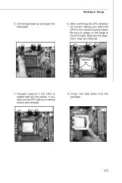
User Guide - Page 22
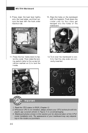
...the holes of the mainboard.
11. Push down to confirm that the clip-ends are for demonstration of your CPU socket pin with the
plastic cap covered (shown in Figure 1) to lock the h ook s .
12. Turn over... load plate, and then secure the lever with the heatsink. MS-7519 Mainboard
9. The appearance of the CPU/
cooler installation only. Mainboard photos shown in BIOS (Chapter 3). 2.
User Guide - Page 25
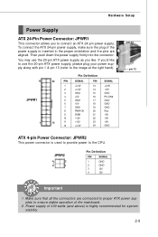
...: JPWR1
This connector allows you to ensure stable operation of the mainboard.
2. If you like to use the 20-pin ATX power supply, please plug your power supply along with pin 1 & pin 13 (refer to the image at the right hand).
12
JPWR1
1
Pin Definition
24
PIN
SIGNAL
PIN
SIGNAL
1
+3.3V
13
+3....
User Guide - Page 30

... Fan cooler set with +12V.
CINTRU 1 GND 2
JCI1
2-14 the black wire is opened, the chassis intrusion mechanism will record this status and show a warning ...MS-7519 Mainboard
Fan Power Connectors: CPUFAN1, SYSFAN1, SYSFAN2
The fan power connectors support system cooling fan with 3 or 4 pins power connector are both available for proper CPU cooling fan.
2. W hen connecting the wire...
User Guide - Page 31
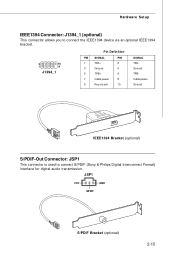
... to connect the IEEE1394 device via an optional IEEE1394 bracket.
2
10
1
9
J1394_1
Pin Definition
PIN SIGNAL
PIN
1
TPA+
2
3
Ground
4
5
TPB+
6
7
Cable power
8
9
Key (no pin)
10
SIGNAL TPAGround TPBCable power Ground
IEEE1394 Bracket (optional)
S/PDIF-Out Connector: JSP1
This connector is used to connect S/PDIF (Sony & Philips Digital Interconnect Format) interface for...
User Guide - Page 32

...PLED
6
BUZ-
7
NC
8
SPK+
DESCRIPTION
Ground SpeakerSuspend LED Buzzer+ Power LED BuzzerNo connection Speaker+
CD-In Connector: JCD1
This connector is compliant ...16 The JFP1 is provided for electrical connection to GND Reserved. MS-7519 Mainboard
Front Panel Connectors: JFP1, JFP2
These connectors are for external audio input. PIN Power Power
LED Switch
1
+-
2
JFP1
2 1
10
3
9
...
User Guide - Page 33

... LAD3
LPC address & data pin3
13 LFRAME# LPCFrame
Pin Signal 2 3V_STB 4 VCC3 6 SIRQ 8 VCC5 10 KEY 12 GND 14 GND
Description 3V standby power 3.3V power Serial IRQ 5V power No pin Ground Ground
2-17 Please refer to connect the front panel audio and is compliant with Intel® Front Panel I/O Connectivity Design...
User Guide - Page 35
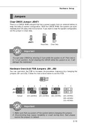
...W ith the CMOS RAM, the system can automatically boot OS every time it will damage the mainboard. If you power off . it is a CMOS RAM onboard that you want to clear the system configuration, set the FSB.
JB2...while the system is off the system before changing the jumpers. 2. Make sure that has a power supply from an external battery to clear data.
3
3
1
JBAT1
1 Keep Data
1 ...
User Guide - Page 36

... specifications.
32-bit PCI Slot
Important
When adding or removing expansion cards, make sure that you unplug the power supply first. The PCI Express 2.0x 16 supports up to 250 MB/s transfer rate. MS-7519 Mainboard
Slots
PCI (Peripheral Component Interconnect) Express Slot
The PCI Express slot supports the PCI Express interface...
User Guide - Page 40

... and the system will start POST (Power On Self Test) process. You may... or pressing the RESET button. It is the BIOS version. V1.0 refers to the BIOS version. 040108 refers to the date this chapter are under each... N = nVidia, and V = VIA. 7th - 8th digit refers to the customer as MS = all standard customers. Important
1. The items under continuous update for reference only.
2.
Upon boot...
User Guide - Page 50
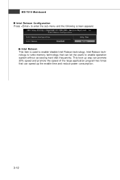
Intel Robson technology is used to enable operation system without accessing hard disk frequenctly. MS-7519 Mainboard Intel Robson Configuration Press to enter the sub-menu and the following screen appears:
Intel Robson This item is turbo ... program two times that can let the users to enable/ disable Intel Robson technology. This boot up the enable time and reduce power consumption.
3-12
User Guide - Page 85
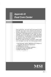
... drive for reference only. Operation system: W indows XP. 5. Dual Core Center
Appendix B
Dual Core Center
Dual CoreCenter, the most useful and powerful utility that MSI has spent much research and efforts to develop, helps users to monitor or configure the hardware status of MSI Mainboard & MSI Graphics card in this appendix are for software installation. 4.
Similar Questions

Where Can I Purchase The P45 Diamond Motherboard Ms-7516 V1.0 Drivers Cd?
(Posted by blackbootheng6836 9 years ago)

Need Network Driver For My Msi Motherboard Ms#7597 Ver. 2.0
(Posted by Anonymous-140116 9 years ago)

Graphics Card
which card would suit model KM 400-8235 motherboard MS-6734
which card would suit model KM 400-8235 motherboard MS-6734
(Posted by vanrooyenrene 10 years ago)

How To Reset Bios On Msi Motherboard Ms-7309 Ver:2.1
(Posted by fieclip 10 years ago)

915gv-m3 Motherboard As Fitted To Acer Power Fg,circa 2004
There are two pairs of ram slots.What is the maximum memory that can be fitted and recognised by the...
There are two pairs of ram slots.What is the maximum memory that can be fitted and recognised by the...
(Posted by david79834 11 years ago)