User Guide
Page 2
... given as to make changes without notice. Alternatively, please try the following help resources for P7N SLI Date March 2008 Technical Support If a problem arises with your place of AMD Corporation. Trademarks All trademarks are the properties of M ICRO-STAR INTERNATIONAL. Award® is a registered trademark of Microsoft Corporation. Visit the MSI website for FAQ, technical guide, BIOS updates, driver updates, and other countries...
... given as to make changes without notice. Alternatively, please try the following help resources for P7N SLI Date March 2008 Technical Support If a problem arises with your place of AMD Corporation. Trademarks All trademarks are the properties of M ICRO-STAR INTERNATIONAL. Award® is a registered trademark of Microsoft Corporation. Visit the MSI website for FAQ, technical guide, BIOS updates, driver updates, and other countries...
User Guide
Page 8
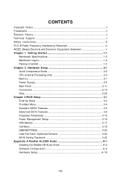
... Guide 2-2 CPU (Central Processing Unit 2-3 Memory ...2-7 Power Supply ...2-9 Back Panel ...2-11 Connectors ...2-13 Slots ...2-20 Chapter 3 BIOS Setup 3-1 Entering Setup ...3-2 The Main Menu ...3-4 Standard CMOS Features 3-6 Advanced BIOS Features 3-9 Integrated Peripherals 3-12 Power Management Setup 3-14 H/W Monitor ...3-17 Cell Menu ...3-18 USERSETTINGS 3-23 Load Fail-Safe/ Optimized Defaults 3-24 BIOS Setting Password 3-25 Appendix A Realtek ALC888 Audio A-1 Installing the Realtek HD Audio Driver A-2 Software Configuration A-4 Hardware Setup A-19 viii Getting Started...
... Guide 2-2 CPU (Central Processing Unit 2-3 Memory ...2-7 Power Supply ...2-9 Back Panel ...2-11 Connectors ...2-13 Slots ...2-20 Chapter 3 BIOS Setup 3-1 Entering Setup ...3-2 The Main Menu ...3-4 Standard CMOS Features 3-6 Advanced BIOS Features 3-9 Integrated Peripherals 3-12 Power Management Setup 3-14 H/W Monitor ...3-17 Cell Menu ...3-18 USERSETTINGS 3-23 Load Fail-Safe/ Optimized Defaults 3-24 BIOS Setting Password 3-25 Appendix A Realtek ALC888 Audio A-1 Installing the Realtek HD Audio Driver A-2 Software Configuration A-4 Hardware Setup A-19 viii Getting Started...

User Guide
Page 12
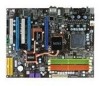
... - 9 mounting holes 1-3 supports SLI technology - 2 PCI slots, support 3.3V/ 5V PCI bus Interface Form Factor - two blue PCI Express x16 slots, each one supports up to PCIE 2.0 x8 c. Getting Started RAID - 4 SATA ports support RAID 0/ 1/ 0+1/ 5 or JBOD mode Floppy - 1 floppy port - Supports 1 FDD with 360KB, 720KB, 1.2MB, 1.44MB and 2.88MB Connectors Back panel - 1 PS/2 mouse port - 1 PS/2 keyboard port - 1 IEEE 1394 port (optional) - 1 Optical SPDIF-Out port - 1 Clear CMOS button - 4 USB 2.0 ports - 1 LAN jack - 6 flexible audio jacks On-Board Pinheaders - 1 Chassis Intrusion pinheader...
... - 9 mounting holes 1-3 supports SLI technology - 2 PCI slots, support 3.3V/ 5V PCI bus Interface Form Factor - two blue PCI Express x16 slots, each one supports up to PCIE 2.0 x8 c. Getting Started RAID - 4 SATA ports support RAID 0/ 1/ 0+1/ 5 or JBOD mode Floppy - 1 floppy port - Supports 1 FDD with 360KB, 720KB, 1.2MB, 1.44MB and 2.88MB Connectors Back panel - 1 PS/2 mouse port - 1 PS/2 keyboard port - 1 IEEE 1394 port (optional) - 1 Optical SPDIF-Out port - 1 Clear CMOS button - 4 USB 2.0 ports - 1 LAN jack - 6 flexible audio jacks On-Board Pinheaders - 1 Chassis Intrusion pinheader...

User Guide
Page 23
... ATX 8-Pin Power Connector: JPWR2 This power connector is used to provide power to avoid wrong installation. Make sure that all the connectors are aligned. Power supply of the mainboard. 2. Then push down the power supply firmly into the connector. There is highly recommended for system stability. 2-9 You may use the 20-pin ATX power supply as you like to use the 20-pin ATX power supply, please plug your power supply along with pin 1 & pin 13 (refer to connect an ATX 24-pin power supply. To connect...
... ATX 8-Pin Power Connector: JPWR2 This power connector is used to provide power to avoid wrong installation. Make sure that all the connectors are aligned. Power supply of the mainboard. 2. Then push down the power supply firmly into the connector. There is highly recommended for system stability. 2-9 You may use the 20-pin ATX power supply as you like to use the 20-pin ATX power supply, please plug your power supply along with pin 1 & pin 13 (refer to connect an ATX 24-pin power supply. To connect...

User Guide
Page 27
... This connector supports IDE hard disk drives, optical disk drives and other IDE devices. IDE1 can also connect a Master and a Slave drive. Refer to IDE device's documentation supplied by setting jumpers. IDE2 (Secondary IDE Connector) IDE2 can connect a Master and a Slave drive. Important If you install two IDE devices on the same cable, you must configure the drives separately to IDE1. IDE2 IDE1 IDE1 (Primary IDE Connector) The first hard drive should always be connected to master / slave mode by the vendors for jumper setting instructions...
... This connector supports IDE hard disk drives, optical disk drives and other IDE devices. IDE1 can also connect a Master and a Slave drive. Refer to IDE device's documentation supplied by setting jumpers. IDE2 (Secondary IDE Connector) IDE2 can connect a Master and a Slave drive. Important If you install two IDE devices on the same cable, you must configure the drives separately to IDE1. IDE2 IDE1 IDE1 (Primary IDE Connector) The first hard drive should always be connected to master / slave mode by the vendors for jumper setting instructions...

User Guide
Page 34
... Slot supports up to PCI Express x 8 speed (PCI_E2/ PCI_E3) Important When adding or removing expansion cards, make sure that you unplug the power supply first. MS-7380 Mainboard Slots PCI (Peripheral Component Interconnect) Express Slots The PCI Express slot supports the PCI Express interface expansion card. The PCI Express 2.0 x 16 supports up to configure any necessary hardware or software settings for the expansion card to 8.0 GB/s transfer rate. Meanwhile, read the documentation for the expansion card, such as jumpers, switches or BIOS configuration...
... Slot supports up to PCI Express x 8 speed (PCI_E2/ PCI_E3) Important When adding or removing expansion cards, make sure that you unplug the power supply first. MS-7380 Mainboard Slots PCI (Peripheral Component Interconnect) Express Slots The PCI Express slot supports the PCI Express interface expansion card. The PCI Express 2.0 x 16 supports up to configure any necessary hardware or software settings for the expansion card to 8.0 GB/s transfer rate. Meanwhile, read the documentation for the expansion card, such as jumpers, switches or BIOS configuration...

User Guide
Page 35
... graphics card. Make sure that you connect an adequate power supply to the power connector on the graphics card to ensure stable operation of the graphics card. 4.If you intend to install only ONE graphics card, make sure that although you only need to connect a monitor to use the SLI mode for demonstration only. To utilize this section are of the same brand and specifications. 3. Hardware Setup NV SLI Technology NVIDIA SLI (Scalable Link Interface) technology...
... graphics card. Make sure that you connect an adequate power supply to the power connector on the graphics card to ensure stable operation of the graphics card. 4.If you intend to install only ONE graphics card, make sure that although you only need to connect a monitor to use the SLI mode for demonstration only. To utilize this section are of the same brand and specifications. 3. Hardware Setup NV SLI Technology NVIDIA SLI (Scalable Link Interface) technology...
User Guide
Page 37
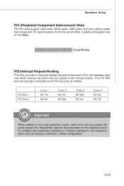
... PCI bus pins as jumpers, switches or BIOS configuration. 2-23 Hardware Setup PCI (Peripheral Component Interconnect) Slots The PCI slots support LAN cards, SCSI cards, USB cards, and other add-on cards that you unplug the power supply first. At 32 bits and 33 MHz, it yields a throughput rate of 133 MBps. 32-bit PCI Slot PCI Interrupt Request Routing The IRQ, acronym of interrupt request line and pronounced I-R-Q, are typically connected to configure any necessary hardware or software settings...
... PCI bus pins as jumpers, switches or BIOS configuration. 2-23 Hardware Setup PCI (Peripheral Component Interconnect) Slots The PCI slots support LAN cards, SCSI cards, USB cards, and other add-on cards that you unplug the power supply first. At 32 bits and 33 MHz, it yields a throughput rate of 133 MBps. 32-bit PCI Slot PCI Interrupt Request Routing The IRQ, acronym of interrupt request line and pronounced I-R-Q, are typically connected to configure any necessary hardware or software settings...
User Guide
Page 44
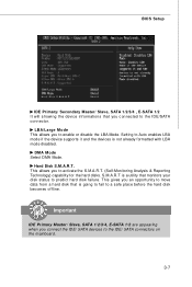
... disk status to Auto enables LBA mode if the device supports it and the devices is going to fail to a safe place before the hard disk becomes offline. Important IDE Primary Master/ Slave, SATA 1/2/3/4, E-SATA 1/2 are appearing when you to activate the S.M.A.R.T. (Self-Monitoring Analysis & Reporting Technology) capability for the hard disks. LBA/Large M ode This allows you connect the IDE/ SATA devices to the IDE/SATA connector. Setting to predict hard disk failure. Hard Disk S.M.A.R.T. DM A M ode Select DMA Mode. BIOS Setup IDE...
... disk status to Auto enables LBA mode if the device supports it and the devices is going to fail to a safe place before the hard disk becomes offline. Important IDE Primary Master/ Slave, SATA 1/2/3/4, E-SATA 1/2 are appearing when you to activate the S.M.A.R.T. (Self-Monitoring Analysis & Reporting Technology) capability for the hard disks. LBA/Large M ode This allows you connect the IDE/ SATA devices to the IDE/SATA connector. Setting to predict hard disk failure. Hard Disk S.M.A.R.T. DM A M ode Select DMA Mode. BIOS Setup IDE...
User Guide
Page 46
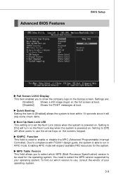
... turn on the Num Lock key when the system is powered on the full screen at boot. [Disabled] Shows the POST messages at boot. You need to enable or disable the APIC (Advanced Programmable Interrupt Controller). Settings are: [Enabled] Shows a still image (logo) on . IOAPIC Function This field is to run in APIC mode. Advanced BIOS Features BIOS Setup Full Screen LOGO Display This item enables you to select which version...
... turn on the Num Lock key when the system is powered on the full screen at boot. [Disabled] Shows the POST messages at boot. You need to enable or disable the APIC (Advanced Programmable Interrupt Controller). Settings are: [Enabled] Shows a still image (logo) on . IOAPIC Function This field is to run in APIC mode. Advanced BIOS Features BIOS Setup Full Screen LOGO Display This item enables you to select which version...

User Guide
Page 47
... to 3 The Max CPUID Value Limit is your primary graphics adapter. MS-7380 Mainboard Primary Graphic's Adapter This setting specifies which graphics card is designed to limit the listed speed of the processor to older operating systems. Chipset Feature Press to enter the sub-menu and the following screen appears: Execute Bit Support Intel's Execute Disable Bit functionality can prevent certain classes of the chipset. For better PCI performance, you...
... to 3 The Max CPUID Value Limit is your primary graphics adapter. MS-7380 Mainboard Primary Graphic's Adapter This setting specifies which graphics card is designed to limit the listed speed of the processor to older operating systems. Chipset Feature Press to enter the sub-menu and the following screen appears: Execute Bit Support Intel's Execute Disable Bit functionality can prevent certain classes of the chipset. For better PCI performance, you...

User Guide
Page 50
... to enable/ disable IDE Controller. I/O Devices Press to enter the sub-menu and the following screen appears: COM Port 1 Select an address and corresponding interrupt for SATA hard disks. BIOS Setup On-Chip ATA Devices Press to enter the sub-menu and the following screen appears: On-Chip IDE Controller This item allows you to enable RAID for SATA 1/2/3/4. RAID mode Setting this option to [RAID] activates the following fields to enable or disable the SATA controller. PCI IDE BusMaster This item allows you to enable/ disable BIOS to use...
... to enable/ disable IDE Controller. I/O Devices Press to enter the sub-menu and the following screen appears: COM Port 1 Select an address and corresponding interrupt for SATA hard disks. BIOS Setup On-Chip ATA Devices Press to enter the sub-menu and the following screen appears: On-Chip IDE Controller This item allows you to enable RAID for SATA 1/2/3/4. RAID mode Setting this option to [RAID] activates the following fields to enable or disable the SATA controller. PCI IDE BusMaster This item allows you to enable/ disable BIOS to use...

User Guide
Page 52
... turned off. Restore On AC Power Loss This item specifies whether your system will be awakened from S3 power saving modes when input signal of the card does not support the initialization feature, the display may work abnormally or not function after a power failure or interrupt occurs. BIOS Setup Re-Call VGA BIOS From S3 W hen ACPI Standby State is set to wake up (resumes) from S3 power...
... turned off. Restore On AC Power Loss This item specifies whether your system will be awakened from S3 power saving modes when input signal of the card does not support the initialization feature, the display may work abnormally or not function after a power failure or interrupt occurs. BIOS Setup Re-Call VGA BIOS From S3 W hen ACPI Standby State is set to wake up (resumes) from S3 power...

User Guide
Page 54
CPU Smart FAN Target The mainboard provides the Smart Fan function which can select a fan temperature target value. CPU M in a specific range. The setting of minimum speed limit for cooling down automatically . FAN Speed (%) W hen you to select percentage of the field will be activated. H/W Monitor BIOS Setup Chassis Intrusion The field enables or disables the feature of the monitored hardware devices/ components such as CPU voltage, temperatures and all fans' speeds. 3-17 You can control the CPU fan speed automatically depending...
CPU Smart FAN Target The mainboard provides the Smart Fan function which can select a fan temperature target value. CPU M in a specific range. The setting of minimum speed limit for cooling down automatically . FAN Speed (%) W hen you to select percentage of the field will be activated. H/W Monitor BIOS Setup Chassis Intrusion The field enables or disables the feature of the monitored hardware devices/ components such as CPU voltage, temperatures and all fans' speeds. 3-17 You can control the CPU fan speed automatically depending...
User Guide
Page 56
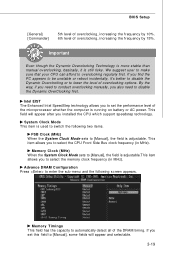
... 10%. 6th level of the DRAM timing. If you installed the CPU which support speedstep technology. We suggest user to make sure that your CPU can afford to [Manual], some fields will appear after you set the performance level of overclocking options. BIOS Setup [General] [Commander] 5th level of overclocking, increasing the frequency by 15%. Memory Clock (M Hz) W hen the System Clock Mode sets to [Manual], the field is adjustable.This...
... 10%. 6th level of the DRAM timing. If you installed the CPU which support speedstep technology. We suggest user to make sure that your CPU can afford to [Manual], some fields will appear after you set the performance level of overclocking options. BIOS Setup [General] [Commander] 5th level of overclocking, increasing the frequency by 15%. Memory Clock (M Hz) W hen the System Clock Mode sets to [Manual], the field is adjustable.This...

User Guide
Page 64
... can get access to 2-, 4-, 6-, 8- Click here Important The HD Audio Configuration software utility is under continuous update to enhance audio applications. MS-7380 Mainboard Installing the Realtek HD Audio Driver You need to install the HD audio driver for Realtek ALC888 codec to function properly before you install the drivers in this section may be slightly different from the latest software utility and shall be held for Windows 2000...
... can get access to 2-, 4-, 6-, 8- Click here Important The HD Audio Configuration software utility is under continuous update to enhance audio applications. MS-7380 Mainboard Installing the Realtek HD Audio Driver You need to install the HD audio driver for Realtek ALC888 codec to function properly before you install the drivers in this section may be slightly different from the latest software utility and shall be held for Windows 2000...

User Guide
Page 87
... and install the nForce RAID software. (Check p.B-7 for details.) 4. Press F10, and the NVIDIA RAID Utility --- Entering the RAID BIOS Setup 1. The default RAID M ode is set to Mirroring and Striping Block is set up the NVRAID BIOS. B-3 Initialize the NVRAID Array Disks. Define a New Array window will reboot right away. Choose the hard disks that has the RAID driver to set to be RAID enabled in BIOS before configuring the NVRAID BIOS. Specify the RAID level...
... and install the nForce RAID software. (Check p.B-7 for details.) 4. Press F10, and the NVIDIA RAID Utility --- Entering the RAID BIOS Setup 1. The default RAID M ode is set to Mirroring and Striping Block is set up the NVRAID BIOS. B-3 Initialize the NVRAID Array Disks. Define a New Array window will reboot right away. Choose the hard disks that has the RAID driver to set to be RAID enabled in BIOS before configuring the NVRAID BIOS. Specify the RAID level...
User Guide
Page 91
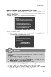
... RAID controller is done. (2) Select "NVIDIA RAID CLASS DRIVER" and then press Enter. (3) Press S again at the Specify Devices screen, then press Enter. (4) Select "NVIDIA NForce Storage Controller" and then press Enter. After you complete the RAID BIOS setup, boot from the W indows CD, and the W indows Setup program starts. The W indows Setup screen appears as below: Important Please follow - Insert the MSI CD into the CD-ROM drive. 2. ing W indows Setup screen appears listing...
... RAID controller is done. (2) Select "NVIDIA RAID CLASS DRIVER" and then press Enter. (3) Press S again at the Specify Devices screen, then press Enter. (4) Select "NVIDIA NForce Storage Controller" and then press Enter. After you complete the RAID BIOS setup, boot from the W indows CD, and the W indows Setup program starts. The W indows Setup screen appears as below: Important Please follow - Insert the MSI CD into the CD-ROM drive. 2. ing W indows Setup screen appears listing...

User Guide
Page 101
... RAID includes extensive support for various morphing combinations. For example, it is possible to another RAID mode. From RAID 0 RAID 1 To RAID 0 RAID 1 RAID 0+1 RAID5 RAID 0 RAID 1 RAID 0+1 RAID 5 New Array Disk Requirements m > n Number of converting from a one RAID array type to morph from a JBOD (Spanning) array - The user must be greater than the previous array. To or from a RAID 1 array to 1 Specific Morphing Requirements The following table lists the disk...
... RAID includes extensive support for various morphing combinations. For example, it is possible to another RAID mode. From RAID 0 RAID 1 To RAID 0 RAID 1 RAID 0+1 RAID5 RAID 0 RAID 1 RAID 0+1 RAID 5 New Array Disk Requirements m > n Number of converting from a one RAID array type to morph from a JBOD (Spanning) array - The user must be greater than the previous array. To or from a RAID 1 array to 1 Specific Morphing Requirements The following table lists the disk...

User Guide
Page 112
... to enter sub-menu to make further configuration or to enable or disable the Dynamic Overclocking Technology. VGA Click VGA button to read current CPU temperature, FSB and CPU clock of mainboard will show below . Dual Core Center Main Before using this utility, we have to remind you install a graphics card of other brand, only hardware status of the MSI mainboard would be available. C-3 MB Click MB button to read current GPU temperature, GPU clock and memory clock of graphics card will...
... to enter sub-menu to make further configuration or to enable or disable the Dynamic Overclocking Technology. VGA Click VGA button to read current CPU temperature, FSB and CPU clock of mainboard will show below . Dual Core Center Main Before using this utility, we have to remind you install a graphics card of other brand, only hardware status of the MSI mainboard would be available. C-3 MB Click MB button to read current GPU temperature, GPU clock and memory clock of graphics card will...


