

User Guide
Page 4
... try to correct the interference by the party responsible for a Class B digital device, pursuant to Part 15 of the FCC Rules. Micro-Star International MS-7366 This device complies with Part 15 of the FCC Rules. This equipment generates, uses and can be used in order to comply with the emission...
... try to correct the interference by the party responsible for a Class B digital device, pursuant to Part 15 of the FCC Rules. Micro-Star International MS-7366 This device complies with Part 15 of the FCC Rules. This equipment generates, uses and can be used in order to comply with the emission...

User Guide
Page 11
The P6NGM Series mainboards are based on GeForce® MCP73U/PV/V chipset for choosing the P6NGM Series (MS-7366 v1.X) Micro-ATX mainboard. Designed to fit the advanced Intel® Pentium 4 LGA775 processor, the P6NGM Series deliver a high performance and professional desktop platform solution. 1-1 Getting Started Chapter 1 Getting Started Thank you for optimal system efficiency.
The P6NGM Series mainboards are based on GeForce® MCP73U/PV/V chipset for choosing the P6NGM Series (MS-7366 v1.X) Micro-ATX mainboard. Designed to fit the advanced Intel® Pentium 4 LGA775 processor, the P6NGM Series deliver a high performance and professional desktop platform solution. 1-1 Getting Started Chapter 1 Getting Started Thank you for optimal system efficiency.
User Guide
Page 12
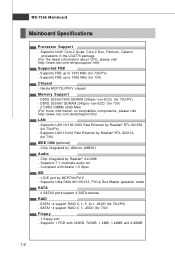
...RAID - SATA1~4 support RAID 0, 1, JBOD (for 73V) - 2 DDR2 DIMMs (4GB Max) (For more information on compatible components, please visit http://www.msi.com.tw/testreport.htm) LAN - Supports 1 FDD with Azalia 1.0 Spec IDE - 1 IDE port by MCP73U/PV/V - Supports LAN 10/100/1000 Fast ... (for 73V) Chipset - Supports FSB up to 1333 MHz (for 73V) IEEE 1394 (optional) - Chip integrated by Realtek® ALC888 - MS-7366 Mainboard Mainboard Specifications Processor Support - Supports Intel® Core 2 Quad, Core 2 Duo, Pentium, Celeron processors in the LGA775 package. (For the latest...
...RAID - SATA1~4 support RAID 0, 1, JBOD (for 73V) - 2 DDR2 DIMMs (4GB Max) (For more information on compatible components, please visit http://www.msi.com.tw/testreport.htm) LAN - Supports 1 FDD with Azalia 1.0 Spec IDE - 1 IDE port by MCP73U/PV/V - Supports LAN 10/100/1000 Fast ... (for 73V) Chipset - Supports FSB up to 1333 MHz (for 73V) IEEE 1394 (optional) - Chip integrated by Realtek® ALC888 - MS-7366 Mainboard Mainboard Specifications Processor Support - Supports Intel® Core 2 Quad, Core 2 Duo, Pentium, Celeron processors in the LGA775 package. (For the latest...

User Guide
Page 14
Out B:Mic T: RS- MS-7366 Mainboard Mainboard Layout IDE 1 PWR2 Top : mouse Bottom: ke y boar d HDMI Port (optional) C PUFA N FDD 1 Top:VGA Port Bottom: DVI Port (optional) JCI1 Top:1394 (... JUSB1 PCI _E2 PCI 1 Jmicron JMB381 ( opt i on al) SYSFAN1 PCI 2 B AT T + J1 JUSB2 JSP1 JU SB3( op tio nal) J1394_1(optional) JFP1 JFP2 JCOM1 P6NGM Series (MS-7366 v1.X) ATX Mainboard 1-4 S ATA 4 SATA 2 S ATA 1 JT PM1 (optional) SATA3
Out B:Mic T: RS- MS-7366 Mainboard Mainboard Layout IDE 1 PWR2 Top : mouse Bottom: ke y boar d HDMI Port (optional) C PUFA N FDD 1 Top:VGA Port Bottom: DVI Port (optional) JCI1 Top:1394 (... JUSB1 PCI _E2 PCI 1 Jmicron JMB381 ( opt i on al) SYSFAN1 PCI 2 B AT T + J1 JUSB2 JSP1 JU SB3( op tio nal) J1394_1(optional) JFP1 JFP2 JCOM1 P6NGM Series (MS-7366 v1.X) ATX Mainboard 1-4 S ATA 4 SATA 2 S ATA 1 JT PM1 (optional) SATA3

User Guide
Page 19
... better heat dispersion. Meanwhile, do not forget to apply some thermal paste on the top to prevent overheating. The pins of your CPU packing. 2-4 MS-7366 Mainboard CPU & Cooler Installation W hen you install the CPU, always cover it to protect the contact from lever hinge side (as the arrow shows). 3. Do...
... better heat dispersion. Meanwhile, do not forget to apply some thermal paste on the top to prevent overheating. The pins of your CPU packing. 2-4 MS-7366 Mainboard CPU & Cooler Installation W hen you install the CPU, always cover it to protect the contact from lever hinge side (as the arrow shows). 3. Do...

User Guide
Page 21
... Important 1. The appearance of the mainboard. 11. Then rotate the locking switch (refer to the correct direction marked on it) to fasten the cooler. MS-7366 Mainboard 9. Press the four hooks down the cooler until its four clips get wedged into the holes of your CPU socket pin with the hook...
... Important 1. The appearance of the mainboard. 11. Then rotate the locking switch (refer to the correct direction marked on it) to fasten the cooler. MS-7366 Mainboard 9. Press the four hooks down the cooler until its four clips get wedged into the holes of your CPU socket pin with the hook...

User Guide
Page 23
... 20-pin ATX power supply, please plug your power supply along with pin 1 & pin 13 (refer to connect an ATX 24-pin power supply. MS-7366 Mainboard Power Supply ATX 24-Pin Power Connector: PWR2 This connector allows you to the image at the right hand). 12 PWR2 1 Pin Definition 24...
... 20-pin ATX power supply, please plug your power supply along with pin 1 & pin 13 (refer to connect an ATX 24-pin power supply. MS-7366 Mainboard Power Supply ATX 24-Pin Power Connector: PWR2 This connector allows you to the image at the right hand). 12 PWR2 1 Pin Definition 24...

User Guide
Page 25
... state) LAN link is communicating with another computer on the LAN. On (brighter & pulsing) The computer is established. Line-Out (Green) - CS-Out (Orange) - MS-7366 Mainboard LAN The standard RJ-45 LAN jack is not established. You can connect a network cable to the Local Area Network (LAN). Center/ Subwoofer Out...
... state) LAN link is communicating with another computer on the LAN. On (brighter & pulsing) The computer is established. Line-Out (Green) - CS-Out (Orange) - MS-7366 Mainboard LAN The standard RJ-45 LAN jack is not established. You can connect a network cable to the Local Area Network (LAN). Center/ Subwoofer Out...
User Guide
Page 27
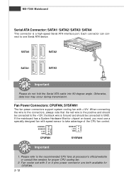
... NS OR +1 2V GND SYSFAN1 Important 1. Please refer to the connectors, always note that the red wire is a high-speed Serial ATA interface port. MS-7366 Mainboard Serial ATA Connector: SATA1/ SATA2/ SATA3/ SATA4 This connector is the positive and should be connected to the +12V; Otherwise, data loss may occur...
... NS OR +1 2V GND SYSFAN1 Important 1. Please refer to the connectors, always note that the red wire is a high-speed Serial ATA interface port. MS-7366 Mainboard Serial ATA Connector: SATA1/ SATA2/ SATA3/ SATA4 This connector is the positive and should be connected to the +12V; Otherwise, data loss may occur...

User Guide
Page 29
MS-7366 Mainboard Front Panel Connectors: JFP1, JFP2 These connectors are for electrical connection to GND Reserved. Do not use. 2-14 JFP2 Pin Definition PIN SIGNAL 1 GND 2 ...
MS-7366 Mainboard Front Panel Connectors: JFP1, JFP2 These connectors are for electrical connection to GND Reserved. Do not use. 2-14 JFP2 Pin Definition PIN SIGNAL 1 GND 2 ...

User Guide
Page 31
... Definition 2 10 1 9 J1394_1 PIN SIGNAL PIN 1 TPA+ 2 3 Ground 4 5 TPB+ 6 7 Cable power 8 9 Key (no pin) 10 SIGNAL TPAGround TPBCable power Ground 2-16 IEEE1394 Bracket (Optional) MS-7366 Mainboard Front USB Connector: JUSB1 / JUSB2 / JUSB3(optional) This connector, compliant with Intel® I/O Connectivity Design Guide, is ideal for connecting high-speed USB interface...
... Definition 2 10 1 9 J1394_1 PIN SIGNAL PIN 1 TPA+ 2 3 Ground 4 5 TPB+ 6 7 Cable power 8 9 Key (no pin) 10 SIGNAL TPAGround TPBCable power Ground 2-16 IEEE1394 Bracket (Optional) MS-7366 Mainboard Front USB Connector: JUSB1 / JUSB2 / JUSB3(optional) This connector, compliant with Intel® I/O Connectivity Design Guide, is ideal for connecting high-speed USB interface...

User Guide
Page 33
Then return to clear data. it is off. If you want to clear the system configuration, set the jumper to 1-2 pin position. J1 1 3 1 Keep Data 3 1 Clear Data Important You can automatically boot OS every time it will damage the mainboard. 2-18 MS-7366 Mainboard Jumpers Clear CMOS Jumper: J1 There is on . W ith the CMOS RAM, the system can clear CMOS by shorting 2-3 pin while the system is turned on ; Avoid clearing the CMOS while the system is a CMOS RAM onboard that has a power supply from an external battery to keep the data of system configuration.
Then return to clear data. it is off. If you want to clear the system configuration, set the jumper to 1-2 pin position. J1 1 3 1 Keep Data 3 1 Clear Data Important You can automatically boot OS every time it will damage the mainboard. 2-18 MS-7366 Mainboard Jumpers Clear CMOS Jumper: J1 There is on . W ith the CMOS RAM, the system can clear CMOS by shorting 2-3 pin while the system is turned on ; Avoid clearing the CMOS while the system is a CMOS RAM onboard that has a power supply from an external battery to keep the data of system configuration.

User Guide
Page 37
Therefore, the description may also restart the system by turning it OFF and On or pressing the RESET button. MS-7366 Mainboard Entering Setup Power on the screen, press key to the date this chapter are under each BIOS category described in the format: A7366NMS V1.0 ...
Therefore, the description may also restart the system by turning it OFF and On or pressing the RESET button. MS-7366 Mainboard Entering Setup Power on the screen, press key to the date this chapter are under each BIOS category described in the format: A7366NMS V1.0 ...

User Guide
Page 39
... menu to specify your settings for stable system performance. 3-4 Power Management Features Use this menu for basic system configurations, such as time, date etc. MS-7366 Mainboard The Main Menu Standard CMOS Features Use this menu to setup the items of AMI® special enhanced features.
... menu to specify your settings for stable system performance. 3-4 Power Management Features Use this menu for basic system configurations, such as time, date etc. MS-7366 Mainboard The Main Menu Standard CMOS Features Use this menu to setup the items of AMI® special enhanced features.

User Guide
Page 41
... adjusted by numeric function keys. Date (MM:DD:YY) This allows you to set the system time that you want (usually the current time). MS-7366 Mainboard Standard CMOS Features The items in each item.
... adjusted by numeric function keys. Date (MM:DD:YY) This allows you to set the system time that you want (usually the current time). MS-7366 Mainboard Standard CMOS Features The items in each item.

User Guide
Page 43
MS-7366 Mainboard Floppy A This item allows you to enter the sub-menu, and the following screen appears. Available options: [None], [360K, 5.25 in.], [1.2M, 5.25 in.], [720K, 3.5 in.], [1.44M, 3.5 in.], [2.88M, 3.5 in.]. System Information Press to set the type of your system (read only). 3-8 This sub-menu shows the CPU information, BIOS version and memory status of floppy drives installed.
MS-7366 Mainboard Floppy A This item allows you to enter the sub-menu, and the following screen appears. Available options: [None], [360K, 5.25 in.], [1.2M, 5.25 in.], [720K, 3.5 in.], [1.44M, 3.5 in.], [2.88M, 3.5 in.]. System Information Press to set the type of your system (read only). 3-8 This sub-menu shows the CPU information, BIOS version and memory status of floppy drives installed.
User Guide
Page 45
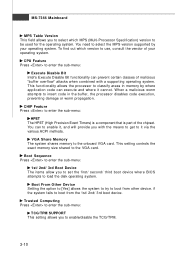
... Bit functionality can to enable it, and will provide you with a supporting operating system. CHIP Feature Press to be used for the operating system. MS-7366 Mainboard MPS Table Version This field allows you to select which version to load the disk operating system. You need to it cannot.
... Bit functionality can to enable it, and will provide you with a supporting operating system. CHIP Feature Press to be used for the operating system. MS-7366 Mainboard MPS Table Version This field allows you to select which version to load the disk operating system. You need to it cannot.

User Guide
Page 47
SATA1 / 2 / 3 / 4 Channel W hen the RAID Mode sets to RAID, these items will available.These items allow users to enable or disable the SATA controller. MS-7366 Mainboard On-Chip SATA Controller This item allows you to enable or disable the RAID function for each SATA hard disk drive. I/O Device Press to enable/disable the RAID function for the first serial port. 3-12 RAID Mode This item is used to enter the sub-menu: COM Port 1 Select an address and corresponding interrupt for SATA devices.
SATA1 / 2 / 3 / 4 Channel W hen the RAID Mode sets to RAID, these items will available.These items allow users to enable or disable the SATA controller. MS-7366 Mainboard On-Chip SATA Controller This item allows you to enable or disable the RAID function for each SATA hard disk drive. I/O Device Press to enable/disable the RAID function for the first serial port. 3-12 RAID Mode This item is used to enter the sub-menu: COM Port 1 Select an address and corresponding interrupt for SATA devices.
User Guide
Page 49
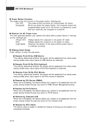
.... [Last State] Restores the system to be awakened from the power saving modes through any event on a scheduled time/date. 3-14 Settings are detected. MS-7366 Mainboard Power Button Function This feature sets the function of booting up the system on the onboard LAN.
.... [Last State] Restores the system to be awakened from the power saving modes through any event on a scheduled time/date. 3-14 Settings are detected. MS-7366 Mainboard Power Button Function This feature sets the function of booting up the system on the onboard LAN.

User Guide
Page 51
... these settings to reserve the IRQ by the system BIOS. After receiving the signal, when the operating system is configured by the I/O device. 3-16 MS-7366 Mainboard IRQ Resource Setup Press to it signals this by causing an IRQ to [Reserved], and IRQ 14/15 are configurable by assigning an [Reserved...
... these settings to reserve the IRQ by the system BIOS. After receiving the signal, when the operating system is configured by the I/O device. 3-16 MS-7366 Mainboard IRQ Resource Setup Press to it signals this by causing an IRQ to [Reserved], and IRQ 14/15 are configurable by assigning an [Reserved...