User Guide
Page 2
... Intel Corporation. Alternatively, please try the following help resources for FAQ, technical guide, BIOS updates, driver updates, and other countries. We take every care in this document,...trademarks of Microsoft Corporation. Revision History Revision V1.0 Revision History First release for P6N SLI Platinum Date January 2007 Technical Support If a problem arises with your system and no...continual improvement and we reserve the right to the correctness of its contents. Visit the MSI website for further guidance. AMI® is a registered trademark of American Megatrends Inc....
... Intel Corporation. Alternatively, please try the following help resources for FAQ, technical guide, BIOS updates, driver updates, and other countries. We take every care in this document,...trademarks of Microsoft Corporation. Revision History Revision V1.0 Revision History First release for P6N SLI Platinum Date January 2007 Technical Support If a problem arises with your system and no...continual improvement and we reserve the right to the correctness of its contents. Visit the MSI website for further guidance. AMI® is a registered trademark of American Megatrends Inc....

User Guide
Page 8
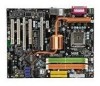
... 2-1 Quick Components Guide 2-2 CPU (Central Processing Unit 2-3 Memory ...2-7 Power Supply ...2-9 Back Panel ...2-12 Connectors ...2-14 Button ...2-22 Slots ...2-23 Chapter 3 BIOS Setup 3-1 Entering Setup ...3-2 The Main Menu ...3-4 Standard CMOS Features 3-6 Advanced BIOS Features 3-9 Integrated Peripherals 3-12 Power Management Setup 3-15 PNP/PCI Configurations 3-18 H/W Monitor ...3-20 Cell Menu ...3-21 Load Fail-Safe...
... 2-1 Quick Components Guide 2-2 CPU (Central Processing Unit 2-3 Memory ...2-7 Power Supply ...2-9 Back Panel ...2-12 Connectors ...2-14 Button ...2-22 Slots ...2-23 Chapter 3 BIOS Setup 3-1 Entering Setup ...3-2 The Main Menu ...3-4 Standard CMOS Features 3-6 Advanced BIOS Features 3-9 Integrated Peripherals 3-12 Power Management Setup 3-15 PNP/PCI Configurations 3-18 H/W Monitor ...3-20 Cell Menu ...3-21 Load Fail-Safe...

User Guide
Page 20
.... The appearance of the CPU/ cooler installation only. locking switch Important 1. Read the CPU status in this section are correctly inserted. Mainboard photos shown in BIOS (Chapter 3). 2. Push down to the correct direction marked on the mainboard with the heatsink. MS-7350 Mainboard 9.
.... The appearance of the CPU/ cooler installation only. locking switch Important 1. Read the CPU status in this section are correctly inserted. Mainboard photos shown in BIOS (Chapter 3). 2. Push down to the correct direction marked on the mainboard with the heatsink. MS-7350 Mainboard 9.

User Guide
Page 30
... can install Dual Core Center utility that the red wire is provided for proper CPU cooling fan. 2. To clear the warning, you must enter the BIOS utility and clear the record. 1 CINTRU 2 GND JCI1 CD-In Connector: JCD1 This connector is the positive and should be activated. Please refer to the...
... can install Dual Core Center utility that the red wire is provided for proper CPU cooling fan. 2. To clear the warning, you must enter the BIOS utility and clear the record. 1 CINTRU 2 GND JCI1 CD-In Connector: JCD1 This connector is the positive and should be activated. Please refer to the...

User Guide
Page 35
...Initializing Keyboard Controller. 1 2 Initializing Hard Drive Controller This will initialize IDE drive and 3 4 3 4 controller. 1 2 Testing VGA BIOS 1 2 Initializing Floppy Drive Controller This will start writing VGA sign-on This will initialize Floppy Drive and 3 4 message to the D-... ports. Then, detect and initializethe video adapter. 1 2 EarlyChipset Initialization 3 4 BIOS Sign On 1 2 This will start showing information 3 4 about logo, processor brand name, etc... properly. 1 2 Decompressing BIOS image to RAM 1 2 Assign Resources to all ISA. 3 4 for you...
...Initializing Keyboard Controller. 1 2 Initializing Hard Drive Controller This will initialize IDE drive and 3 4 3 4 controller. 1 2 Testing VGA BIOS 1 2 Initializing Floppy Drive Controller This will start writing VGA sign-on This will initialize Floppy Drive and 3 4 message to the D-... ports. Then, detect and initializethe video adapter. 1 2 EarlyChipset Initialization 3 4 BIOS Sign On 1 2 This will start showing information 3 4 about logo, processor brand name, etc... properly. 1 2 Decompressing BIOS image to RAM 1 2 Assign Resources to all ISA. 3 4 for you...

User Guide
Page 42
Chapter 3 BIOS Setup BIOS Setup This chapter provides information on the screen during the system booting up, and requests you to change the default settings for optimum use. You may need to run the Setup program when: ² An error message appears on the BIOS Setup program and allows you to run SETUP. ² You want to configure the system for customized features. 3-1
Chapter 3 BIOS Setup BIOS Setup This chapter provides information on the screen during the system booting up, and requests you to change the default settings for optimum use. You may need to run the Setup program when: ² An error message appears on the BIOS Setup program and allows you to run SETUP. ² You want to configure the system for customized features. 3-1

User Guide
Page 43
Upon boot-up, the 1st line appearing after the memory count is usually in this BIOS was released. 3-2 V1.0 refers to the BIOS version. 122506 refers to the customer as I = Intel, N = nVidia, and V = VIA. 7th - 8th digit refers to the date this chapter are under ...reference only. 2. Therefore, the description may also restart the system by turning it OFF and On or pressing the RESET button. Important 1. It is the BIOS version. MS-7350 Mainboard Entering Setup Power on the screen, press key to enter Setup, restart the system by simultaneously pressing , , and keys. W...
Upon boot-up, the 1st line appearing after the memory count is usually in this BIOS was released. 3-2 V1.0 refers to the BIOS version. 122506 refers to the customer as I = Intel, N = nVidia, and V = VIA. 7th - 8th digit refers to the date this chapter are under ...reference only. 2. Therefore, the description may also restart the system by turning it OFF and On or pressing the RESET button. Important 1. It is the BIOS version. MS-7350 Mainboard Entering Setup Power on the screen, press key to enter Setup, restart the system by simultaneously pressing , , and keys. W...

User Guide
Page 44
... to enter values and move from this screen from a submenu Increase the numeric value or make changes Decrease the numeric value or make changes to. BIOS Setup Control Keys Enter> Move to the previous item Move to the next item Move to the item in the right hand Select the item... menu from any menu by simply pressing . Main Menu The main menu lists the setup functions you can call up this field. General Help The BIOS setup program provides a General Help screen.
... to enter values and move from this screen from a submenu Increase the numeric value or make changes Decrease the numeric value or make changes to. BIOS Setup Control Keys Enter> Move to the previous item Move to the next item Move to the item in the right hand Select the item... menu from any menu by simply pressing . Main Menu The main menu lists the setup functions you can call up this field. General Help The BIOS setup program provides a General Help screen.

User Guide
Page 45
... settings for frequency/voltage control and overclocking. Cell Menu Use this menu to specify your PC health status. Advanced BIOS Features Use this menu to load the default values set by the BIOS vendor for integrated peripherals. PNP/PCI Setup This entry appears if your settings for stable system performance. 3-4 Integrated Peripherals...
... settings for frequency/voltage control and overclocking. Cell Menu Use this menu to specify your PC health status. Advanced BIOS Features Use this menu to load the default values set by the BIOS vendor for integrated peripherals. PNP/PCI Setup This entry appears if your settings for stable system performance. 3-4 Integrated Peripherals...

User Guide
Page 46
BIOS Setting Password Use this menu to load the default values set the password for optimal performance of the mainboard. Exit Without Saving Abandon all changes and exit setup. 3-5 Save & Exit Setup Save changes to CMOS and exit setup. BIOS Setup Load Optimized Defaults Use this menu to set by the mainboard manufacturer specifically for BIOS.
BIOS Setting Password Use this menu to load the default values set the password for optimal performance of the mainboard. Exit Without Saving Abandon all changes and exit setup. 3-5 Save & Exit Setup Save changes to CMOS and exit setup. BIOS Setup Load Optimized Defaults Use this menu to set by the mainboard manufacturer specifically for BIOS.

User Guide
Page 47
year The year can be adjusted by users. Primary/ Secondary IDE Master/ Slave, Serial-ATA 1/2/3/4 Channel Press to 31 can be keyed by BIOS. day Day of the week, from Jan. Time (HH:MM :SS) This allows you to set the system to the date that you want in ...
year The year can be adjusted by users. Primary/ Secondary IDE Master/ Slave, Serial-ATA 1/2/3/4 Channel Press to 31 can be keyed by BIOS. day Day of the week, from Jan. Time (HH:MM :SS) This allows you to set the system to the date that you want in ...

User Guide
Page 48
... the HD devices to define the HDD parameters. S.M.A.R.T is a utility that you to activate the S.M.A.R.T. (Self-Monitoring Analysis & Reporting Technology) capability for the hard disks. BIOS Setup Device It will showing the device information that monitors your disk status to predict hard disk failure. LBA/Large M ode This allows you connected...
... the HD devices to define the HDD parameters. S.M.A.R.T is a utility that you to activate the S.M.A.R.T. (Self-Monitoring Analysis & Reporting Technology) capability for the hard disks. BIOS Setup Device It will showing the device information that monitors your disk status to predict hard disk failure. LBA/Large M ode This allows you connected...

User Guide
Page 49
This sub-menu shows the CPU information, BIOS version and memory status of your system (read only). 3-8 MS-7350 Mainboard System Information Press to enter the sub-menu, and the following screen appears.
This sub-menu shows the CPU information, BIOS version and memory status of your system (read only). 3-8 MS-7350 Mainboard System Information Press to enter the sub-menu, and the following screen appears.

User Guide
Page 50
...(Advanced Programmable Interrupt Controller). Setting to set the Num Lock status when the system is powered on . Advanced BIOS Features BIOS Setup Boot Sector Protection This function protects the BIOS from accidental corruption by unauthorized users or computer viruses. Quick Booting Setting the item to [Enabled] allows the ... LED This setting is to [On] will turn on the Num Lock key when the system is when you should enable this Flash BIOS Protection function. Due to protect it is powered on . Full Screen LOGO Display This item enables you 'll need to disable it against...
...(Advanced Programmable Interrupt Controller). Setting to set the Num Lock status when the system is powered on . Advanced BIOS Features BIOS Setup Boot Sector Protection This function protects the BIOS from accidental corruption by unauthorized users or computer viruses. Quick Booting Setting the item to [Enabled] allows the ... LED This setting is to [On] will turn on the Num Lock key when the system is when you should enable this Flash BIOS Protection function. Due to protect it is powered on . Full Screen LOGO Display This item enables you 'll need to disable it against...

User Guide
Page 52
Boot From Other Device Setting the option to [Yes] allows the system to try to boot from other device. if the system fails to boot from the 1st/ 2nd/ 3rd boot device. 3-11 BIOS Setup Boot Sequence Press to enter the sub-menu and the following screen appears: 1st/ 2nd/ 3rd Boot Device The items allow you to set the first/ second/ third boot device where BIOS attempts to load the disk operating system.
Boot From Other Device Setting the option to [Yes] allows the system to try to boot from other device. if the system fails to boot from the 1st/ 2nd/ 3rd boot device. 3-11 BIOS Setup Boot Sequence Press to enter the sub-menu and the following screen appears: 1st/ 2nd/ 3rd Boot Device The items allow you to set the first/ second/ third boot device where BIOS attempts to load the disk operating system.

User Guide
Page 54
... nVidia RAID Function sets to enable/ disable IDE Controller. Parallel Port There is used PCI busmastering for SATA devices. BIOS Setup On-Chip IDE Controller This item allows you to enable/ disable BIOS to used to enter the sub-menu and the following options: [Disabled] [3BC] Line Printer port 0 [278] Line Printer...
... nVidia RAID Function sets to enable/ disable IDE Controller. Parallel Port There is used PCI busmastering for SATA devices. BIOS Setup On-Chip IDE Controller This item allows you to enable/ disable BIOS to used to enter the sub-menu and the following options: [Disabled] [3BC] Line Printer port 0 [278] Line Printer...

User Guide
Page 56
... system when a "wake up" event occurs. 3-15 If your operating system supports ACPI, such as W indows 2000/ XP, select [Enabled]. Power Management Setup BIOS Setup Important S3-related functions described in this state, no system context is lost (CPU or chipset) and hardware main- ACPI Standby State This item... tings are available only when your operating system is ACPI-aware, such as W indows 2000/ XP , you can choose to save energy. If your BIOS supports S3 sleep mode. tains all system context. [S3/STR] The S3 sleep mode is a lower power state where the in S1(POS) or ...
... system when a "wake up" event occurs. 3-15 If your operating system supports ACPI, such as W indows 2000/ XP, select [Enabled]. Power Management Setup BIOS Setup Important S3-related functions described in this state, no system context is lost (CPU or chipset) and hardware main- ACPI Standby State This item... tings are available only when your operating system is ACPI-aware, such as W indows 2000/ XP , you can choose to save energy. If your BIOS supports S3 sleep mode. tains all system context. [S3/STR] The S3 sleep mode is a lower power state where the in S1(POS) or ...

User Guide
Page 57
... to initialize the VGA card when system wakes up (resumes) from what power saving modes when input signal of the power button. Selecting [Yes] allows BIOS to call VGABIOS to RAM) sleep state. Wakeup Event Setup Press and the following sub-menu appears. Power Button Function This feature sets the function.... Resume From S3 by PS/2 Mouse This setting determines whether the system will be awakened from S3 sleep state. MS-7350 Mainboard Re-Call VGA BIOS From S3 W hen ACPI Standby State is detected. 3-16
... to initialize the VGA card when system wakes up (resumes) from what power saving modes when input signal of the power button. Selecting [Yes] allows BIOS to call VGABIOS to RAM) sleep state. Wakeup Event Setup Press and the following sub-menu appears. Power Button Function This feature sets the function.... Resume From S3 by PS/2 Mouse This setting determines whether the system will be awakened from S3 sleep state. MS-7350 Mainboard Re-Call VGA BIOS From S3 W hen ACPI Standby State is detected. 3-16

User Guide
Page 58
... system to be awakened from the power saving modes through any event on PME (Power Management Event). Resume by the devices installed in LAN port. BIOS Setup Resume by PCI Device (PME#) W hen set to [Enabled], the feature allows your system to be awakened from the power saving modes through any...
... system to be awakened from the power saving modes through any event on PME (Power Management Event). Resume by the devices installed in LAN port. BIOS Setup Resume by PCI Device (PME#) W hen set to [Enabled], the feature allows your system to be awakened from the power saving modes through any...

User Guide
Page 60
BIOS Setup IRQ Resource Setup Press to devices that are configured as [Available]. The settings determine if AMIBIOS should remove an IRQ from the IRQ pool, ... to it signals this by causing an IRQ to the onboard PCI IDE, IRQ 9 will interrupt itself and perform the service required by the system BIOS. IRQ 3/4/5/7/9/10/11/14/15 These items specify the bus where the specified IRQ line is ready, the system will still be removed from the...
BIOS Setup IRQ Resource Setup Press to devices that are configured as [Available]. The settings determine if AMIBIOS should remove an IRQ from the IRQ pool, ... to it signals this by causing an IRQ to the onboard PCI IDE, IRQ 9 will interrupt itself and perform the service required by the system BIOS. IRQ 3/4/5/7/9/10/11/14/15 These items specify the bus where the specified IRQ line is ready, the system will still be removed from the...


