
User Guide
Page 24
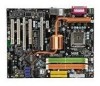
To connect the ATX 24-pin power supply, make sure the plug of the mainboard. 2. You may use the 20-pin ATX power supply, please plug your power supply along with pin 1 & pin 13 (refer to the image at the right hand). Pin Definition 12 24 PIN SIGNAL PIN SIGNAL ATX1 1 13 1 +3.3V 13 +3.3V 2 +3.3V 14...10 +12V 22 +5V 11 +12V 23 +5V 12 +3.3V 24 GND pin 13 pin 12 ATX 12V Power Connector: JPW1 This power connector is also a foolproof design on pin 11, 12, 23 & 24 to connect an ATX 24-pin power supply. Then push down the power supply firmly into the connector. Make...
To connect the ATX 24-pin power supply, make sure the plug of the mainboard. 2. You may use the 20-pin ATX power supply, please plug your power supply along with pin 1 & pin 13 (refer to the image at the right hand). Pin Definition 12 24 PIN SIGNAL PIN SIGNAL ATX1 1 13 1 +3.3V 13 +3.3V 2 +3.3V 14...10 +12V 22 +5V 11 +12V 23 +5V 12 +3.3V 24 GND pin 13 pin 12 ATX 12V Power Connector: JPW1 This power connector is also a foolproof design on pin 11, 12, 23 & 24 to connect an ATX 24-pin power supply. Then push down the power supply firmly into the connector. Make...

User Guide
Page 27
...mouse, or other audio devices. You can differentiate the color of S/PDIF-out, coaxial S/PDIF-out, optical S/PDIF-out, or onboard 2-pin S/PDIF-out connector for HDMI graphics card, otherwise the audio transmission will shine blue light when the connector is a connector for speakers or...) connector is a connector for audio devices. Line In / Side-Surround Out in 7.1 channel mode, is used for microphones. Line Out, is connected. Center/ Subwoofer Out in 4/ 5.1/ 7.1 channel mode. Line-In (Blue) - Indicator LED 2-13 The indicator LED beside the e-SATA connector and will be ...
...mouse, or other audio devices. You can differentiate the color of S/PDIF-out, coaxial S/PDIF-out, optical S/PDIF-out, or onboard 2-pin S/PDIF-out connector for HDMI graphics card, otherwise the audio transmission will shine blue light when the connector is a connector for speakers or...) connector is a connector for audio devices. Line In / Side-Surround Out in 7.1 channel mode, is used for microphones. Line Out, is connected. Center/ Subwoofer Out in 4/ 5.1/ 7.1 channel mode. Line-In (Blue) - Indicator LED 2-13 The indicator LED beside the e-SATA connector and will be ...

User Guide
Page 30
...Power Connectors: CPUFAN, SYSFAN1, SYSFAN2, SYSFAN3 The fan power connectors support system cooling fan with 3 or 4 pins are both available for external audio input. W hen connecting the wire to the connectors, always note that will automatically control the CPU fan speed according to the chassis ...CD-In Connector: JCD1 This connector is Ground and should be activated. the black wire is provided for CPUFAN. The system will be connected to the recommended CPU fans at processor's official website or consult the vendors for proper CPU cooling fan. 2. If the mainboard has...
...Power Connectors: CPUFAN, SYSFAN1, SYSFAN2, SYSFAN3 The fan power connectors support system cooling fan with 3 or 4 pins are both available for external audio input. W hen connecting the wire to the connectors, always note that will automatically control the CPU fan speed according to the chassis ...CD-In Connector: JCD1 This connector is Ground and should be activated. the black wire is provided for CPUFAN. The system will be connected to the recommended CPU fans at processor's official website or consult the vendors for proper CPU cooling fan. 2. If the mainboard has...

User Guide
Page 31
PRESENCE# = 0 when a High Definition Audio dongle is compliant with Intel® Front Panel I/O Connectivity Design Guide. You can attach a serial device. 2 1 9 JCOM1 Pin Definition PIN SIGNAL 1 DCD 2 SIN 3 SOUT 4 DTR 5 GND 6 DSR 7 RTS 8 CTS 9 RI DESCRIPTION Data Carry Detect Serial In or Receive Data Serial Out or Transmit Data Data ...
PRESENCE# = 0 when a High Definition Audio dongle is compliant with Intel® Front Panel I/O Connectivity Design Guide. You can attach a serial device. 2 1 9 JCOM1 Pin Definition PIN SIGNAL 1 DCD 2 SIN 3 SOUT 4 DTR 5 GND 6 DSR 7 RTS 8 CTS 9 RI DESCRIPTION Data Carry Detect Serial In or Receive Data Serial Out or Transmit Data Data ...

User Guide
Page 32
MS-7350 Mainboard Front USB Connector: JUSB1 / JUSB2 This connector, compliant with Intel® I/O Connectivity Design Guide, is ideal for connecting high-speed USB interface peripherals such as USB HDD, digital cameras, MP3 players, printers, modems and the like. 2 10 1 9 JUSB1 / JUSB2 Pin Definition PIN SIGNAL 1 VCC 3 USB0- 5 USB0+ 7 GND 9 Key (no pin) PIN SIGNAL 2 VCC 4 USB1- 6 USB1+ 8 GND 10 NC Connected to USB connector USB 2.0 Bracket (Optional) Important Note that the pins of VCC and GND must be connected correctly to avoid possible damage. 2-18
MS-7350 Mainboard Front USB Connector: JUSB1 / JUSB2 This connector, compliant with Intel® I/O Connectivity Design Guide, is ideal for connecting high-speed USB interface peripherals such as USB HDD, digital cameras, MP3 players, printers, modems and the like. 2 10 1 9 JUSB1 / JUSB2 Pin Definition PIN SIGNAL 1 VCC 3 USB0- 5 USB0+ 7 GND 9 Key (no pin) PIN SIGNAL 2 VCC 4 USB1- 6 USB1+ 8 GND 10 NC Connected to USB connector USB 2.0 Bracket (Optional) Important Note that the pins of VCC and GND must be connected correctly to avoid possible damage. 2-18

User Guide
Page 33
... This connector allows you to the HDMI graphics card. 1 SPDIFO 2 GND SPDO1 2-19 Pin Definition 2 10 1 9 J1394_1 (The 1394 connector is in Green color.) PIN SIGNAL PIN 1 TPA+ 2 3 Ground 4 5 TPB+ 6 7 Cable power 8 9 Key (no pin) 10 SIGNAL TPAGround TPBCable power Ground Connected to 1394 connector Foolproof design IEEE1394 Bracket (Optional) S/PDIF-Out Connector: SPDO1 (Optional...
... This connector allows you to the HDMI graphics card. 1 SPDIFO 2 GND SPDO1 2-19 Pin Definition 2 10 1 9 J1394_1 (The 1394 connector is in Green color.) PIN SIGNAL PIN 1 TPA+ 2 3 Ground 4 5 TPB+ 6 7 Cable power 8 9 Key (no pin) 10 SIGNAL TPAGround TPBCable power Ground Connected to 1394 connector Foolproof design IEEE1394 Bracket (Optional) S/PDIF-Out Connector: SPDO1 (Optional...

User Guide
Page 34
... 1 GND 2 SPK- 3 SLED 4 BUZ+ 5 PLED 6 BUZ- 7 NC 8 SPK+ DESCRIPTION Ground SpeakerSuspend LED Buzzer+ Power LED BuzzerNo connection Speaker+ 2-20 HDD 1 + LED JFP1 Pin Definition PIN SIGNAL 1 HD_LED + 2 FP PW R/SLP 3 HD_LED - 4 FP PW R/SLP 5 RST_SW - 6 PW R_SW + 7 RST_SW + 8 PW R_SW - 9 RSVD_DNU DESCRIPTION Hard disk LED pull-... Switch + Power LED 2 9 +Reset - Switch - Do not use. MS-7350 Mainboard Front Panel Connectors: JFP1, JFP2 These connectors are for electrical connection to GND Reserved. The JFP1 is compliant with Intel® Front Panel...
... 1 GND 2 SPK- 3 SLED 4 BUZ+ 5 PLED 6 BUZ- 7 NC 8 SPK+ DESCRIPTION Ground SpeakerSuspend LED Buzzer+ Power LED BuzzerNo connection Speaker+ 2-20 HDD 1 + LED JFP1 Pin Definition PIN SIGNAL 1 HD_LED + 2 FP PW R/SLP 3 HD_LED - 4 FP PW R/SLP 5 RST_SW - 6 PW R_SW + 7 RST_SW + 8 PW R_SW - 9 RSVD_DNU DESCRIPTION Hard disk LED pull-... Switch + Power LED 2 9 +Reset - Switch - Do not use. MS-7350 Mainboard Front Panel Connectors: JFP1, JFP2 These connectors are for electrical connection to GND Reserved. The JFP1 is compliant with Intel® Front Panel...

User Guide
Page 35
... Operating System Booting 3 4 3 4 2-21 D-Bracket™ 2 (Optional) DBR1 DBR2 DBR3 DBR4 N C Connected to JDB1 2 10 1 9 DBG1 DBG2 DBG3 DBG4 Key (no-pin) Red LED Signal 1 2 3 4 Connected to 3 D-LED will hang if the memory mod4 ule is damaged or not installed 3 4 640K and extended ...2 Testing onboard memory size. properly. 1 2 Decompressing BIOS image to RAM 1 2 Assign Resources to all ISA. 3 4 for you to connect to the screen. 3 4 controller. 1 Processor Initialization 2 This will show information regarding 1 2 BootAttempt This will set low stack and boot via...
... Operating System Booting 3 4 3 4 2-21 D-Bracket™ 2 (Optional) DBR1 DBR2 DBR3 DBR4 N C Connected to JDB1 2 10 1 9 DBG1 DBG2 DBG3 DBG4 Key (no-pin) Red LED Signal 1 2 3 4 Connected to 3 D-LED will hang if the memory mod4 ule is damaged or not installed 3 4 640K and extended ...2 Testing onboard memory size. properly. 1 2 Decompressing BIOS image to RAM 1 2 Assign Resources to all ISA. 3 4 for you to connect to the screen. 3 4 controller. 1 Processor Initialization 2 This will show information regarding 1 2 BootAttempt This will set low stack and boot via...

User Guide
Page 41
... shine green light when the system is turned on cards that comply with PCI specifications. The PCI IRQ pins are hardware lines over which devices can send interrupt signals to the PCI bus pins as follows: PCI Slot 1 PCI Slot 2 PCI Slot 3 Order 1 INT Y# INT Z# INT W# Order 2 INT Z# INT W# INT X# Order 3 INT... cards, USB cards, and other add-on . At 32 bits and 33 MHz, it yields a throughput rate of interrupt request line and pronounced I-R-Q, are typically connected to the microprocessor.
... shine green light when the system is turned on cards that comply with PCI specifications. The PCI IRQ pins are hardware lines over which devices can send interrupt signals to the PCI bus pins as follows: PCI Slot 1 PCI Slot 2 PCI Slot 3 Order 1 INT Y# INT Z# INT W# Order 2 INT Z# INT W# INT X# Order 3 INT... cards, USB cards, and other add-on . At 32 bits and 33 MHz, it yields a throughput rate of interrupt request line and pronounced I-R-Q, are typically connected to the microprocessor.


