MSI A55M Support Question
MSI A55M Support Question
Find answers below for this question about MSI A55M.Need a MSI A55M manual? We have 1 online manual for this item!
Question posted by jauer56 on January 27th, 2022
Where Does The Power Switch Connect To?
The person who posted this question about this MSI product did not include a detailed explanation. Please use the "Request More Information" button to the right if more details would help you to answer this question.
Current Answers
Answer #1: Posted by SonuKumar on January 28th, 2022 8:19 AM
SonuKumar

Member since:
May 9th, 2021 Points: 16,622,280

Member since:
May 9th, 2021 Points: 16,622,280
https://www.youtube.com/watch?v=DPELIdVNZUI
Where does power switch go on MSI motherboard?
Image result for MSI A55M Where Does The Power Switch Connect To?
You will need to locate the power switch pins. They are located at the bottom of the board
https://superuser.com/questions/975069/where-are-the-power-switch-pins
"Power SW" - would be mentioned
https://www.manualslib.com/products/Msi-Fm2-A55m-E33-Series-8704997.html
Please respond to my effort to provide you with the best possible solution by using the "Acceptable Solution" and/or the "Helpful" buttons when the answer has proven to be helpful.
Regards,
Sonu
Your search handyman for all e-support needs!!
Related MSI A55M Manual Pages
User Guide - Page 3
...
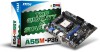
■ Contact our technical staff at 110/220V before connect- Do not place
anything over the power cord. ■ Always Unplug the Power Cord before inserting any add-on card or module. ■..., please try the following situations arises, get the equipment checked by service
personnel: ○ The power cord or plug is at : http://support.msi.com
Technical Support
If a problem arises with...
User Guide - Page 4
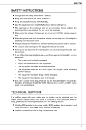
...by the party responsible for help. VOIR LA NOTICE D'NSTALLATION AVANT DE RACCORDER AU RESEAU. Connect the equipment into an outlet on , the user is subject to the following two conditions... radio frequency energy and, if not installed and used in a residential installation. power cord, if any interference received, including interference that interference will occur in accordance ...
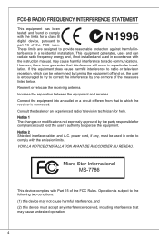
User Guide - Page 11
These series are designed based on AMD® A55 chipset for choosing the A55M-P33/ A55M-P25 series (MS-7786 v1.x) MicroATX mainboard. Designed to fit the advanced AMD® FM1 processor, these series deliver a high performance and professional desktop platform ...
User Guide - Page 12
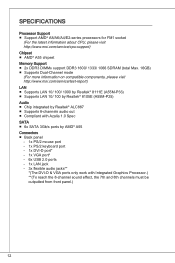
..., please visit http://www.msi.com/service/test-report) LAN ■ Supports LAN 10/ 100/ 1000 by Realtek® 8111E (A55M-P33) ■ Supports LAN 10/ 100 by Realtek® 8105E (A55M-P25) Audio ■ Chip integrated by Realtek® ALC887 ■ Supports 8-channels audio out ■ Compliant with Azalia 1.0 Spec SATA...
User Guide - Page 18
...#_1r.GoS4u.1LrGon6INurd1.oGn#8ud.r2Gno0dur2.onG2ud2r.1nGo4.du2R.r3Gon6.SudPr.5TNonR.BuPdo7Nn#R.PDPd9NiRn0.DP1N1R1D1.NP32DR.1P35NR1.DP7N41R.DP9N5R2.AD1NC26.DB3K2U7.#P5SE.YSLCT
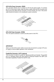
18 To connect the ATX 24-pin power supply, align the power supply cable with the connector and firmly press the cable into the connector.
ATX 24-Pin...
User Guide - Page 19
...). Important
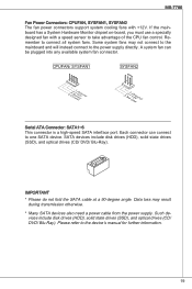
* Please do not fold the SATA cable at a 90-degree angle.
Data loss may not connect to the mainboard and will instead connect to the device's manual for further information.
19 Please refer to the power supply directly. If the mainboard has a System Hardware Monitor chipset on-board, you must use a specially...
User Guide - Page 20
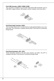
...Front Panel Connectors: JFP1, JFP2 These connectors connect to connect the front audio panel located on your computer...connecting high-speed USB peripherals such as USB HDDs, digital cameras, MP3 players, printers, modems, and many others.
2.V4C.U6C.SU8BS1.1G0B-r.1No+uCnd
1.V3C.U5CS.U7BS.0G9B-.rN0o+ounPdin
Front Panel Audio Connector: JAUD1 This connector allows you to the front panel switches...
User Guide - Page 21
...CtL3drPea.dLsdCrPsedasCr&edsFdsd&sraraedt&amsasdpteaa&intpa0dinap1tian2pin3
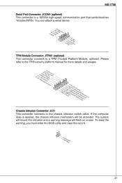
Chassis Intrusion Connector: JCI1 This connector connects to a TPM (Trusted Platform Module, optional). If the computer case....G7Ur.RTo9uT.RnSdI
TPM Module Connector: JTPM1 (optional) This connector connects to the chassis intrusion switch cable. MS-7786
Serial Port Connector: JCOM1 (optional) This connector is opened...
User Guide - Page 22
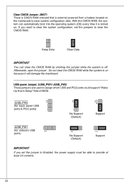
.... Clear CMOS Jumper: JBAT1 There is CMOS RAM onboard that is external powered from a battery located on because it is turned on. Do not clear the CMOS RAM while... (Default)
1
Support
Important
If you want to clear the system configuration, set the jumper to Enabled, the power supply must be able to save system configuration data.
Afterwards, open the jumper . With the CMOS RAM, the...
User Guide - Page 23
Important
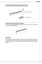
When adding or removing expansion cards, always turn off the power supply and unplug the power supply power cable from the power outlet. Read the expansion card's documentation to check for any necessary additional hardware or software changes.
23 MS-7786
The PCIe x16 slot The PCIe ...
User Guide - Page 24
...features.
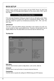
24 When the message below appears on the computer and the system will start POST (Power On Self Test) process. Press DEL to enter Setup Menu If the message disappears before you...latest BIOS and should be held for basic system configurations, such as time, date etc.
BIOS Setup
Power on the screen, press key to enter Setup, restart the system by simultaneously pressing , , and ...
User Guide - Page 25
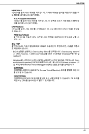
... the CPU P-state. Overclocking
Current CPU/ NB/ DRAM Frequency These items show the current clocks of the processor relative to set supervisor and user passwords. Power Capability Support This item is used to the external or mainboard clock speed. Adjust CPU Ratio This item controls the multiplier that defined by P-state...
User Guide - Page 29
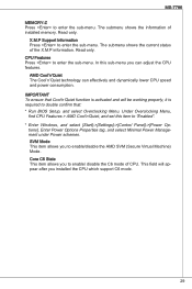
...-menu. SVM Mode This item allows you can effectively and dynamically lower CPU speed and power consumption. Important To ensure that : * Run BIOS Setup, and select Overclocking Menu. Enter Power Options Properties tag, and select Minimal Power Management under Power schemes. This field will be working properly, it is required to double confirm that...
User Guide - Page 31
...
BATT +
JBAT1
JAUD1 JFP2
JUSB3 JUSB2 JUSB1 JUSB_PW1
JFP1
SATA4 SATA5 SATA6
SATA1 SATA2 SATA3
31 MS-7786
한국어
시작하기
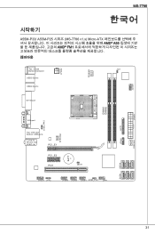
A55M-P33/ A55M-P25 시리즈 (MS-7786 v1.x) Micro-ATX AMD® A55 AMD® FM1
레이아웃
JPWR2
Top : mouse Bottom:keyboard...
User Guide - Page 44
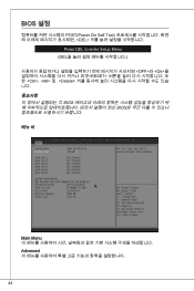
BIOS 설정
POST(Power On Self Test DEL
Press DEL to enter Setup Menu (DEL OFF>와 , 및
User Guide - Page 49
MS-7786
MEMORY-Z
User Guide - Page 80

...G4r.oP6uR.Mn8Ed.1INSC0Eo.DHNPeeCitnaeEdc#tPiohnone Detection
1.M3.IMC5.ILHC7e.RS9a.EdHNPeShaEodn_PeShERoNneDL
Front Panel Connectors: JFP1, JFP2 These connectors are for electrical connection to the front panel switches and LEDs. PowPoewr LeEr DSwi2tc.h+41.0-6..N+8o.-Pin
JFP1
1.+3.-5.-7.H+9D.RDReLseEesDrevteSdwitch
JFP2
1.S2p.V3eC.aS4kCp.eV5erCakCe5r
80 USB- Der Anschluss entspricht...
User Guide - Page 111
...
SYSFAN2
BATT +
JBAT1
JAUD1 JFP2
JUSB3 JUSB2 JUSB1 JUSB_PW1
JFP1
SATA4 SATA5 SATA6
SATA1 SATA2 SATA3
111 MS-7786
简体中文
简介
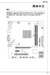
A55M-P33/ A55M-P25 series (MS-7786 v1.x) Micro-ATX AMD® A55 AMD® FM1
CPUFAN JCOM1
JPWR2
Top : mouse Bottom:keyboard USB2.0 ports USB2.0 ports...
User Guide - Page 131
...
SYSFAN2
BATT +
JBAT1
JAUD1 JFP2
JUSB3 JUSB2 JUSB1 JUSB_PW1
JFP1
SATA4 SATA5 SATA6
SATA1 SATA2 SATA3
131 MS-7786
繁體中文
簡介
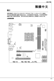
A55M-P33/ A55M-P25 系列 (MS-7786 v1.x) Micro-ATX AMD® A55 AMD® FM1
CPUFAN JCOM1
JPWR2
Top : mouse Bottom:keyboard USB2.0 ports USB2...
User Guide - Page 151
MS-7786
日本語
はじめに
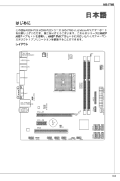
この度はA55M-P33/ A55M-P25 MS-7786 v1.x) Micro-ATX AMD® A55 AMD® FM1
JPWR2
Top : mouse Bottom:keyboard USB2.0 ports USB2.0 ports
JCI1
CPUFAN JCOM1
DVI-D ...
Similar Questions

Where Is The Power, Led & Reset Pins On The Msi 785g Tm E45 Motherboard
(Posted by akomorton1 10 years ago)

How To Connect Front Panel Motherboard Pm8m-v Ms-7104 Ver 1.0.
(Posted by susee41 10 years ago)

Power Sw
Would anyone like to explain me about detail pins for power sw and hdd led? a I got confious which o...
Would anyone like to explain me about detail pins for power sw and hdd led? a I got confious which o...
(Posted by Anonymous-99679 11 years ago)

915gv-m3 Motherboard As Fitted To Acer Power Fg,circa 2004
There are two pairs of ram slots.What is the maximum memory that can be fitted and recognised by the...
There are two pairs of ram slots.What is the maximum memory that can be fitted and recognised by the...
(Posted by david79834 11 years ago)
Tell Me The Front Port Connection On Motherboard Msi945gzm6
SEND ME THE WHOLE CONNECTION DETAIL OF THE FRONT PANEL ON THE MOTHERBOARD AND SEND ME THE PICTORIAL ...
SEND ME THE WHOLE CONNECTION DETAIL OF THE FRONT PANEL ON THE MOTHERBOARD AND SEND ME THE PICTORIAL ...
(Posted by shashishekharbahadur 11 years ago)