User Guide
Page 3
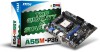
... the MSI website for technical guide, BIOS updates, driver updates, and other information: http://www.msi.com/service/download ■ Contact our technical staff at 110/220V before setting it . Do not cover the openings. ■ Make sure the voltage of the power source ...Support If a problem arises with your place of breakage. ■ DO NOT LEAVE THIS EQUIPMENT IN AN ENVIRONMENT UNCONDITIONED, STORAGE TEMPERATURE ABOVE 60°C (140°F), IT MAY DAMAGE THE EQUIPMENT. MS-7786 Safety Instructions ■ Always read the safety instructions carefully. ■ Keep this User Manual...
... the MSI website for technical guide, BIOS updates, driver updates, and other information: http://www.msi.com/service/download ■ Contact our technical staff at 110/220V before setting it . Do not cover the openings. ■ Make sure the voltage of the power source ...Support If a problem arises with your place of breakage. ■ DO NOT LEAVE THIS EQUIPMENT IN AN ENVIRONMENT UNCONDITIONED, STORAGE TEMPERATURE ABOVE 60°C (140°F), IT MAY DAMAGE THE EQUIPMENT. MS-7786 Safety Instructions ■ Always read the safety instructions carefully. ■ Keep this User Manual...
User Guide
Page 11
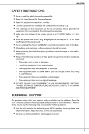
Designed to fit the advanced AMD® FM1 processor, these series deliver a high performance and professional desktop platform solution. Layout JPWR2 Top : mouse Bottom:keyboard USB2.0 ports USB2.0 ports JCI1 CPUFAN JCOM1 DVI-D port SOCKET FM1 DIMM1 DIMM2 JPWR1 JLPT1 SYSFAN1 JTPM1 JUSB_PW2 VGA port Top: LAN Jack Bottom: USB ports T:Line-In M:Line- Out B:MIC-Int PCI _E1 PCI _E2 PCI1 SYSFAN2 BATT + JBAT1 JAUD1 JFP2 JUSB3 JUSB2...
Designed to fit the advanced AMD® FM1 processor, these series deliver a high performance and professional desktop platform solution. Layout JPWR2 Top : mouse Bottom:keyboard USB2.0 ports USB2.0 ports JCI1 CPUFAN JCOM1 DVI-D port SOCKET FM1 DIMM1 DIMM2 JPWR1 JLPT1 SYSFAN1 JTPM1 JUSB_PW2 VGA port Top: LAN Jack Bottom: USB ports T:Line-In M:Line- Out B:MIC-Int PCI _E1 PCI _E2 PCI1 SYSFAN2 BATT + JBAT1 JAUD1 JFP2 JUSB3 JUSB2...
User Guide
Page 12
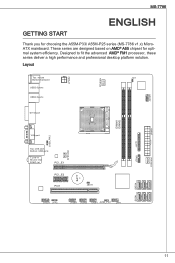
... (A55M-P25) Audio ■ Chip integrated by Realtek® ALC887 ■ Supports 8-channels audio out ■ Compliant with Azalia 1.0 Spec SATA ■ 6x SATA 3Gb/s ports by AMD® A55 Connectors ■ Back panel ‑ 1x PS/2 mouse port ‑ 1x PS/2 keyboard port ‑ 1x DVI-D port* ‑ 1x VGA port* ‑ 6x USB 2.0 ports ‑ 1x LAN jack ‑ 3x flexible audio jacks** *(The DVI-D & VGA ports only work with Integrated Graphics Processor.) **(To reach the 8-channel sound...
... (A55M-P25) Audio ■ Chip integrated by Realtek® ALC887 ■ Supports 8-channels audio out ■ Compliant with Azalia 1.0 Spec SATA ■ 6x SATA 3Gb/s ports by AMD® A55 Connectors ■ Back panel ‑ 1x PS/2 mouse port ‑ 1x PS/2 keyboard port ‑ 1x DVI-D port* ‑ 1x VGA port* ‑ 6x USB 2.0 ports ‑ 1x LAN jack ‑ 3x flexible audio jacks** *(The DVI-D & VGA ports only work with Integrated Graphics Processor.) **(To reach the 8-channel sound...
User Guide
Page 13
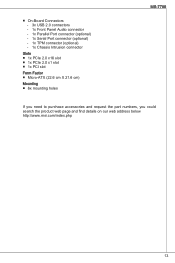
■ On-Board Connectors ‑ 3x USB 2.0 connectors ‑ 1x Front Panel Audio connector ‑ 1x Parallel Port connector (optional) ‑ 1x Serial Port connector (optional) ‑ 1x TPM connector (optional) ‑ 1x Chassis Intrusion connector Slots ■ 1x PCIe 2.0 x16 slot ■ 1x PCIe 2.0 x1 slot ■ 1x PCI slot Form Factor ■ Micro-ATX (22.6 cm X 21.6 cm) Mounting ■ 6x mounting holes MS-7786 If you need to purchase accessories and request the part numbers...
■ On-Board Connectors ‑ 3x USB 2.0 connectors ‑ 1x Front Panel Audio connector ‑ 1x Parallel Port connector (optional) ‑ 1x Serial Port connector (optional) ‑ 1x TPM connector (optional) ‑ 1x Chassis Intrusion connector Slots ■ 1x PCIe 2.0 x16 slot ■ 1x PCIe 2.0 x1 slot ■ 1x PCI slot Form Factor ■ Micro-ATX (22.6 cm X 21.6 cm) Mounting ■ 6x mounting holes MS-7786 If you need to purchase accessories and request the part numbers...
User Guide
Page 15
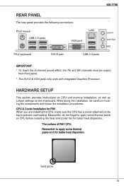
... REAR PANEL The rear panel provides the following connectors: PS/2 mouse USB 2.0 ports LAN VGA port PS/2 keyboard DVI-D port USB 2.0 ports Line-In Line-Out MIC Important * To reach the 8-channel sound effect, the 7th and 8th channels must be careful in holding the components and follow the installation procedures. Gold arrow 15 While doing the installation, be output from front panel. * The DVI-D & VGA ports only work with Integrated Graphics Processor.
... REAR PANEL The rear panel provides the following connectors: PS/2 mouse USB 2.0 ports LAN VGA port PS/2 keyboard DVI-D port USB 2.0 ports Line-In Line-Out MIC Important * To reach the 8-channel sound effect, the 7th and 8th channels must be careful in holding the components and follow the installation procedures. Gold arrow 15 While doing the installation, be output from front panel. * The DVI-D & VGA ports only work with Integrated Graphics Processor.
User Guide
Page 18
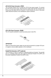
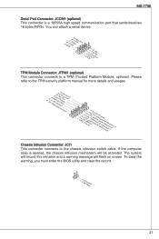
The parallel port is used to connect an ATX 24-pin power supply. To connect the ATX 24-pin power supply, align the power supply cable with the connector and firmly press the cable into the connector. Parallel Port Connector: JLPT1 (optional) This connector is used to provide power to the CPU. 2.G1.rGouronudnd 4.+31.+21V2V Important Make sure that supports Enhanced Parallel Port (EPP) and Extended Capabilities Parallel Port (ECP) mode. 2.A4F.ED6R.#P8RI.1N#L0PI1T.TG2#_1r.GoS4u...
The parallel port is used to connect an ATX 24-pin power supply. To connect the ATX 24-pin power supply, align the power supply cable with the connector and firmly press the cable into the connector. Parallel Port Connector: JLPT1 (optional) This connector is used to provide power to the CPU. 2.G1.rGouronudnd 4.+31.+21V2V Important Make sure that supports Enhanced Parallel Port (EPP) and Extended Capabilities Parallel Port (ECP) mode. 2.A4F.ED6R.#P8RI.1N#L0PI1T.TG2#_1r.GoS4u...
User Guide
Page 19
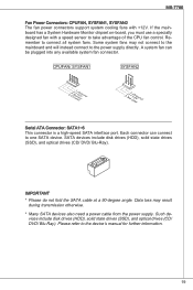
... Hardware Monitor chipset on-board, you must use a specially designed fan with +12V. A system fan can connect to one SATA device. SATA devices include disk drives (HDD), solid state drives (SSD), and optical drives (CD/ DVD/ Blu-Ray). Remember to the device's manual for further information. 19 Each connector can be plugged into any available system fan connector. MS-7786 Fan Power Connectors: CPUFAN, SYSFAN1, SYSFAN2 The fan power connectors support system cooling fans with a speed sensor to take advantage of the CPU fan control...
... Hardware Monitor chipset on-board, you must use a specially designed fan with +12V. A system fan can connect to one SATA device. SATA devices include disk drives (HDD), solid state drives (SSD), and optical drives (CD/ DVD/ Blu-Ray). Remember to the device's manual for further information. 19 Each connector can be plugged into any available system fan connector. MS-7786 Fan Power Connectors: CPUFAN, SYSFAN1, SYSFAN2 The fan power connectors support system cooling fans with a speed sensor to take advantage of the CPU fan control...
User Guide
Page 21
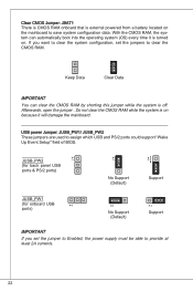
....rwGeionreurornudnd 1.L3P.L5CP.LCC7P.loLRC9cP.eLka1CsPd1e1ad.CtL3drPea.dLsdCrPsedasCr&edsFdsd&sraraedt&amsasdpteaa&intpa0dinap1tian2pin3 Chassis Intrusion Connector: JCI1 This connector connects to a TPM (Trusted Platform Module, optional). MS-7786 Serial Port Connector: JCOM1 (optional) This connector is opened, the chassis intrusion mechanism will flash on screen. To clear the warning, you must enter the BIOS utility and clear the record. 1.C2.IGNTroRuUnd 21 The system will record this intrusion and...
....rwGeionreurornudnd 1.L3P.L5CP.LCC7P.loLRC9cP.eLka1CsPd1e1ad.CtL3drPea.dLsdCrPsedasCr&edsFdsd&sraraedt&amsasdpteaa&intpa0dinap1tian2pin3 Chassis Intrusion Connector: JCI1 This connector connects to a TPM (Trusted Platform Module, optional). MS-7786 Serial Port Connector: JCOM1 (optional) This connector is opened, the chassis intrusion mechanism will flash on screen. To clear the warning, you must enter the BIOS utility and clear the record. 1.C2.IGNTroRuUnd 21 The system will record this intrusion and...
User Guide
Page 22
... CMOS RAM while the system is on . With the CMOS RAM, the system can clear the CMOS RAM by shorting this jumper while the system is off. USB power Jumper: JUSB_PW1/ JUSB_PW2 These jumpers are used to assign which USB and PS/2 ports could support "Wake Up Event Setup" field of BIOS. 1 1 1 1 JUSB_PW2 (for back panel USB ports & PS/2 ports) No Support (Default) Support 1 JUSB_PW1 (for onboard USB 1 ports) 1 No Support (Default) 1 Support Important If you want to clear the system configuration, set the jumper to Enabled, the power supply...
... CMOS RAM while the system is on . With the CMOS RAM, the system can clear the CMOS RAM by shorting this jumper while the system is off. USB power Jumper: JUSB_PW1/ JUSB_PW2 These jumpers are used to assign which USB and PS/2 ports could support "Wake Up Event Setup" field of BIOS. 1 1 1 1 JUSB_PW2 (for back panel USB ports & PS/2 ports) No Support (Default) Support 1 JUSB_PW1 (for onboard USB 1 ports) 1 No Support (Default) 1 Support Important If you want to clear the system configuration, set the jumper to Enabled, the power supply...
User Guide
Page 23
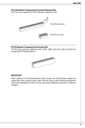
Read the expansion card's documentation to check for any necessary additional hardware or software changes. 23 PCIe (Peripheral Component Interconnect Express) Slot The PCIe slot supports the PCIe interface expansion card. Important When adding or removing expansion cards, always turn off the power supply and unplug the power supply power cable from the power outlet. MS-7786 The PCIe x16 slot The PCIe x1 slot PCI (Peripheral Component Interconnect) Slot The PCI slot supports additional LAN, SCSI, USB, and other add-on cards that comply with PCI specifications.
Read the expansion card's documentation to check for any necessary additional hardware or software changes. 23 PCIe (Peripheral Component Interconnect Express) Slot The PCIe slot supports the PCIe interface expansion card. Important When adding or removing expansion cards, always turn off the power supply and unplug the power supply power cable from the power outlet. MS-7786 The PCIe x16 slot The PCIe x1 slot PCI (Peripheral Component Interconnect) Slot The PCI slot supports additional LAN, SCSI, USB, and other add-on cards that comply with PCI specifications.
User Guide
Page 24
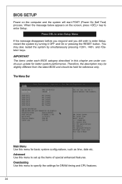
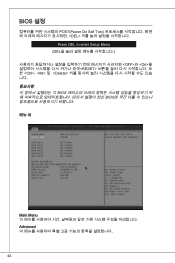
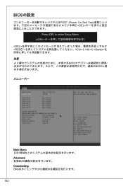
... still wish to enter Setup, restart the system by simultaneously pressing , , and keys. Overclocking Use this chapter are under continuous update for DRAM timing and CPU features. 24 The Menu Bar Main Menu Use this menu to set up the items of special enhanced features. BIOS Setup Power on the screen, press key to enter Setup. When the message below appears on the computer and the system will start POST (Power On Self Test...
... still wish to enter Setup, restart the system by simultaneously pressing , , and keys. Overclocking Use this chapter are under continuous update for DRAM timing and CPU features. 24 The Menu Bar Main Menu Use this menu to set up the items of special enhanced features. BIOS Setup Power on the screen, press key to enter Setup. When the message below appears on the computer and the system will start POST (Power On Self Test...
User Guide
Page 25
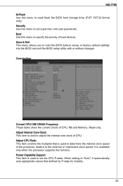
... mainboard clock speed. Overclocking Current CPU/ NB/ DRAM Frequency These items show the current clocks of boot devices. MS-7786 M-Flash Use this menu to set the CPU P-state. Boot Use this function. Power Capability Support This item is used to determine the internal clock speed of CPU. Adjust Internal Core Clock This item is used to set supervisor and user passwords. It is available only when the processor supports this menu to "Auto", it automatically sets appropriate values that is used to load the BIOS default values or factory default settings...
... mainboard clock speed. Overclocking Current CPU/ NB/ DRAM Frequency These items show the current clocks of boot devices. MS-7786 M-Flash Use this menu to set the CPU P-state. Boot Use this function. Power Capability Support This item is used to determine the internal clock speed of CPU. Adjust Internal Core Clock This item is used to set supervisor and user passwords. It is available only when the processor supports this menu to "Auto", it automatically sets appropriate values that is used to load the BIOS default values or factory default settings...
User Guide
Page 26
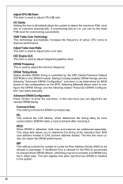
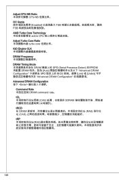
... advanced DRAM timing. DRAM Frequency This is used to adjust integrated graphics clock. Setting to [Auto] enables DRAM timings and the following related "Advanced DRAM Configuration" sub-menu manually. IGD Engine CLK This item is used to adjust the memory frequency. tRCD When DRAM is allowed for Row Address Strobe (RAS) to be incomplete and DRAM may be allowed to retain data. Selecting [Manual] allows users to enter the sub-menu. tCL This controls...
... advanced DRAM timing. DRAM Frequency This is used to adjust integrated graphics clock. Setting to [Auto] enables DRAM timings and the following related "Advanced DRAM Configuration" sub-menu manually. IGD Engine CLK This item is used to adjust the memory frequency. tRCD When DRAM is allowed for Row Address Strobe (RAS) to be incomplete and DRAM may be allowed to retain data. Selecting [Manual] allows users to enter the sub-menu. tCL This controls...
User Guide
Page 28
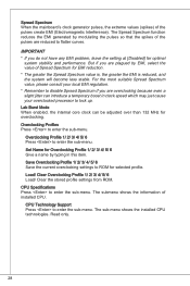
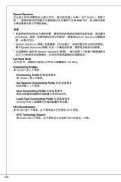
... sub-menu. Load/ Clear Overclocking Profile 1/ 2/ 3/ 4/ 5/ 6 Load/ Clear the stored profile settings from ROM. CPU Technology Support Press to enter the sub-menu. The sub-menu shows the installed CPU technologies. Set Name for EMI reduction. * The greater the Spread Spectrum value is, the greater the EMI is reduced, and the system will become less stable. But if you do not have any EMI problem, leave the setting at [Disabled] for overclocking...
... sub-menu. Load/ Clear Overclocking Profile 1/ 2/ 3/ 4/ 5/ 6 Load/ Clear the stored profile settings from ROM. CPU Technology Support Press to enter the sub-menu. The sub-menu shows the installed CPU technologies. Set Name for EMI reduction. * The greater the Spread Spectrum value is, the greater the EMI is reduced, and the system will become less stable. But if you do not have any EMI problem, leave the setting at [Disabled] for overclocking...
User Guide
Page 29
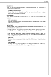
... CPU features. SVM Mode This item allows you installed the CPU which support C6 mode. 29 In this item to "Enabled". * Enter Windows, and select [Start]->[Settings]->[Control Panel]->[Power Options]. Under Overclocking Menu, find CPU Features > AMD Cool'n'Quiet, and set this sub-menu you to double confirm that: * Run BIOS Setup, and select Overclocking Menu. Core C6 State This item allows you can effectively and dynamically lower CPU speed and power consumption. CPU Features Press to enter the sub-menu. Enter Power Options...
... CPU features. SVM Mode This item allows you installed the CPU which support C6 mode. 29 In this item to "Enabled". * Enter Windows, and select [Start]->[Settings]->[Control Panel]->[Power Options]. Under Overclocking Menu, find CPU Features > AMD Cool'n'Quiet, and set this sub-menu you to double confirm that: * Run BIOS Setup, and select Overclocking Menu. Core C6 State This item allows you can effectively and dynamically lower CPU speed and power consumption. CPU Features Press to enter the sub-menu. Enter Power Options...
User Guide
Page 30
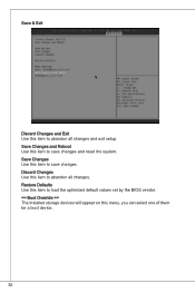
Discard Changes Use this item to save changes. Save Changes and Reboot Use this item to abandon all changes and exit setup. Save Changes Use this menu, you can select one of them be a boot device. 30 Restore Defaults Use this item to load the optimized default values set by the BIOS vendor. == Boot Override == The installed storage devices will appear on this item to save changes and reset the system. Save & Exit Discard Changes and Exit Use this item to abandon all changes.
Discard Changes Use this item to save changes. Save Changes and Reboot Use this item to abandon all changes and exit setup. Save Changes Use this menu, you can select one of them be a boot device. 30 Restore Defaults Use this item to load the optimized default values set by the BIOS vendor. == Boot Override == The installed storage devices will appear on this item to save changes and reset the system. Save & Exit Discard Changes and Exit Use this item to abandon all changes.
User Guide
Page 44
BIOS 설정 POST(Power On Self Test DEL Press DEL to enter Setup Menu (DEL OFF>와 , 및
BIOS 설정 POST(Power On Self Test DEL Press DEL to enter Setup Menu (DEL OFF>와 , 및
User Guide
Page 128
Spread Spectrum EMI EMI [Disabled EMI Spread Spectrum EMI。 * Spread Spectrum EMI Spread Spectrum EMI Spread Spectrum Lab Burst Mode 132 MHz。 Overclocking Profiles 按
Spread Spectrum EMI EMI [Disabled EMI Spread Spectrum EMI。 * Spread Spectrum EMI Spread Spectrum EMI Spread Spectrum Lab Burst Mode 132 MHz。 Overclocking Profiles 按
User Guide
Page 146
Adjust CPU-NB Ratio CPU-NB OC Genie Enabled FSB FSB AMD Turbo Core Technology active CPU Adjust Turbo Core Ratio turbo core IGD Engine CLK DRAM Frequency DRAM Timing Mode DRAM SPD (Serial Presence Detect) EEPROM 來配置 DRAM Auto Advanced DRAM Configuration SPD BIOS Link] 或 [Unlink Advanced DRAM Configuration Advanced DRAM Configuration 按下
Adjust CPU-NB Ratio CPU-NB OC Genie Enabled FSB FSB AMD Turbo Core Technology active CPU Adjust Turbo Core Ratio turbo core IGD Engine CLK DRAM Frequency DRAM Timing Mode DRAM SPD (Serial Presence Detect) EEPROM 來配置 DRAM Auto Advanced DRAM Configuration SPD BIOS Link] 或 [Unlink Advanced DRAM Configuration Advanced DRAM Configuration 按下
User Guide
Page 164
BIOSの設定 POST (Power On Self Test DEL Press DEL to enter Setup Menu (とと
BIOSの設定 POST (Power On Self Test DEL Press DEL to enter Setup Menu (とと


