User Guide
Page 2
... of NVIDIA Corporation in the United States and/or other information: http://global.msi.com.tw/index.php? Copyright Notice The material in this document, but no solution can be obtained from the user's manual, please contact your place of Intel Corporation. We take every care in the... preparation of this document is a registered trademark of Microsoft Corporation. func=service Contact our technical staff at: http://ocss.msi.com.tw ii Trademarks All trademarks are...
... of NVIDIA Corporation in the United States and/or other information: http://global.msi.com.tw/index.php? Copyright Notice The material in this document, but no solution can be obtained from the user's manual, please contact your place of Intel Corporation. We take every care in the... preparation of this document is a registered trademark of Microsoft Corporation. func=service Contact our technical staff at: http://ocss.msi.com.tw ii Trademarks All trademarks are...

User Guide
Page 3
... penetrated into the opening that people can not get the equipment checked by the m an uf ac t ur er. fore connecting the equipment to User's Manual. † The equipment has dropped and damaged. † The equipment has obvious sign of breakage. 12. If any liquid into the equipment. † The equipment... has been exposed to moisture. † The equipment does not work according to the power inlet. 7. Always read the safety instructions carefully. 2. Keep this User's Manual for air convection hence protects the equip-
... penetrated into the opening that people can not get the equipment checked by the m an uf ac t ur er. fore connecting the equipment to User's Manual. † The equipment has dropped and damaged. † The equipment has obvious sign of breakage. 12. If any liquid into the equipment. † The equipment... has been exposed to moisture. † The equipment does not work according to the power inlet. 7. Always read the safety instructions carefully. 2. Keep this User's Manual for air convection hence protects the equip-
User Guide
Page 16
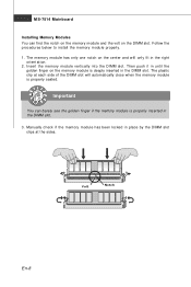
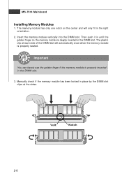
... notch on the memory module and the volt on the memory module is deeply inserted in the DIMM slot. 3. The plastic clip at the sides. Manually check if the memory m odule has been locked in the right ori ent at i on the center and will only fit in place by the...
... notch on the memory module and the volt on the memory module is deeply inserted in the DIMM slot. 3. The plastic clip at the sides. Manually check if the memory m odule has been locked in the right ori ent at i on the center and will only fit in place by the...

User Guide
Page 21
... to increase the processor frequency by changing the jumpers JB1 and JB2. Make sure that you power off the system before changing the jumpers. 2. English ATX 12V Power Connector (2x2-Pin): JPWR2 This 12V power connector is used to provide power to the CPU. 21 GND GND 12V 12V 43 TPM... MHz 333->400 MHz Important 1. En-13 Follow the instructions below to a TPM (Trusted Platform Module) module (optional). Please refer to the TPM security platform manual for more details and usages.
... to increase the processor frequency by changing the jumpers JB1 and JB2. Make sure that you power off the system before changing the jumpers. 2. English ATX 12V Power Connector (2x2-Pin): JPWR2 This 12V power connector is used to provide power to the CPU. 21 GND GND 12V 12V 43 TPM... MHz 333->400 MHz Important 1. En-13 Follow the instructions below to a TPM (Trusted Platform Module) module (optional). Please refer to the TPM security platform manual for more details and usages.
User Guide
Page 28
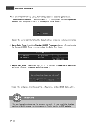
... to enter the Standard CMOS Features-m enu. Adjust the Date, Tim e fields. 3. If you need the detailed settings of BIOS, please see the manual in English version on MSI website. En-20 Important The configuration above are for general use . 1. Setup Date/ Time : Select the Standard CMOS Features and press to load...
... to enter the Standard CMOS Features-m enu. Adjust the Date, Tim e fields. 3. If you need the detailed settings of BIOS, please see the manual in English version on MSI website. En-20 Important The configuration above are for general use . 1. Setup Date/ Time : Select the Standard CMOS Features and press to load...
User Manual
Page 2
...and OS®/2 are registered trademarks or trademarks of NVIDIA Corporation in this document, but no solution can be obtained from the user's manual, please contact your place of M ICRO-STAR INTERNATIONAL. AMI® is a registered trademark of Novell, Inc. func=service Contact our... All trademarks are registered trademarks of Phoenix Technologies Ltd. Award® is the intellectual property of purchase or local distributor. Visit the MSI website for FAQ, technical guide, BIOS updates, driver updates, and other countries. AMD, Athlon™, Athlon™ XP, Thoroughbred™...
...and OS®/2 are registered trademarks or trademarks of NVIDIA Corporation in this document, but no solution can be obtained from the user's manual, please contact your place of M ICRO-STAR INTERNATIONAL. AMI® is a registered trademark of Novell, Inc. func=service Contact our... All trademarks are registered trademarks of Phoenix Technologies Ltd. Award® is the intellectual property of purchase or local distributor. Visit the MSI website for FAQ, technical guide, BIOS updates, driver updates, and other countries. AMD, Athlon™, Athlon™ XP, Thoroughbred™...

User Manual
Page 3
... can not get the equipment checked by the m an uf ac t ur er. Always read the safety instructions carefully. 2. Keep this User's Manual for air convection hence protects the equip- If any liquid into the equipment. † The equipment has been exposed to moisture. † The ...equipment has not work according to the power inlet. 7. fore connecting the equipment to User's Manual. † The equipment has dropped and damaged. † The equipment has obvious sign of expl os i on card or module. 9. ment from humidity. ...
... can not get the equipment checked by the m an uf ac t ur er. Always read the safety instructions carefully. 2. Keep this User's Manual for air convection hence protects the equip- If any liquid into the equipment. † The equipment has been exposed to moisture. † The ...equipment has not work according to the power inlet. 7. fore connecting the equipment to User's Manual. † The equipment has dropped and damaged. † The equipment has obvious sign of expl os i on card or module. 9. ment from humidity. ...
User Manual
Page 22
... clip at the sides. Important You can barely see the golden finger if the memory module is deeply inserted in the right orientation. 2. Volt Notch 2-8 Manually check if the memory module has been locked in place by the DIMM slot clips at each side of the DIMM slot will only fit...
... clip at the sides. Important You can barely see the golden finger if the memory module is deeply inserted in the right orientation. 2. Volt Notch 2-8 Manually check if the memory module has been locked in place by the DIMM slot clips at each side of the DIMM slot will only fit...

User Manual
Page 31
... compliant with Intel® Front Panel I/O Connectivity Design Guide. Hardware Setup Front Panel Audio Connector: JAUD1 This connector allows you to the TPM security platform manual for more details and usages. 12 1314 Pin Signal Description 1 LCLK LPC clock 3 LRST# LPC reset 5 LAD0 LPC address & data pin0 7 LAD1 LPC address & data...
... compliant with Intel® Front Panel I/O Connectivity Design Guide. Hardware Setup Front Panel Audio Connector: JAUD1 This connector allows you to the TPM security platform manual for more details and usages. 12 1314 Pin Signal Description 1 LCLK LPC clock 3 LRST# LPC reset 5 LAD0 LPC address & data pin0 7 LAD1 LPC address & data...
User Manual
Page 56
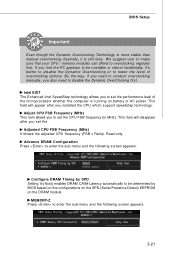
... Press to enter the sub-menu and the following screen appears. BIOS Setup Important Even though the Dynamic Overclocking Technology is more stable than manual overclocking, basically, it 's better to disable the Dynamic Overclocking or to overclocking regularly first. We suggest user to make sure that your ...appear after you to be unstable or reboot incidentally, it is running on the DRAM module. If you also need to conduct overclocking manually, you find the PC appears to be determined by BIOS based on the configurations on the SPD (Serial Presence Detect) EEPROM on battery...
... Press to enter the sub-menu and the following screen appears. BIOS Setup Important Even though the Dynamic Overclocking Technology is more stable than manual overclocking, basically, it 's better to disable the Dynamic Overclocking or to overclocking regularly first. We suggest user to make sure that your ...appear after you to be unstable or reboot incidentally, it is running on the DRAM module. If you also need to conduct overclocking manually, you find the PC appears to be determined by BIOS based on the configurations on the SPD (Serial Presence Detect) EEPROM on battery...

User Manual
Page 87
...it will be powered only when users' PC runs huge amount of data, like 3D games or video process, and the motherboard/ graphicd card need to conduct overclocking manually, please do not to overclock regularly first. DOT FSB-UP Rate button DOT FSB-DOWN Rate button Important Even though the ...for a time, it will be boosted up the CPU and fan automatically to make the system run smoother and faster. B-5 When the motherboard detects that the loading of overclocking options. Usually the Dynamic Overclocking Technology will speed up to enhance the overall performance.
...it will be powered only when users' PC runs huge amount of data, like 3D games or video process, and the motherboard/ graphicd card need to conduct overclocking manually, please do not to overclock regularly first. DOT FSB-UP Rate button DOT FSB-DOWN Rate button Important Even though the ...for a time, it will be boosted up the CPU and fan automatically to make the system run smoother and faster. B-5 When the motherboard detects that the loading of overclocking options. Usually the Dynamic Overclocking Technology will speed up to enhance the overall performance.

User Manual
Page 90
... your system. Or click the Default button to decrease. MS-7514 Mainboard FAN Speed In the FAN Speed sub-menu, you set the fan speed manually, please make sure to disabled the "CPU Smart FAN Target" item in the BIOS. 2. Important 1. On the underside, it . Click the plus sign button to...
... your system. Or click the Default button to decrease. MS-7514 Mainboard FAN Speed In the FAN Speed sub-menu, you set the fan speed manually, please make sure to disabled the "CPU Smart FAN Target" item in the BIOS. 2. Important 1. On the underside, it . Click the plus sign button to...


