User Guide
Page 8
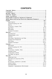
... Interference Statement iv WEEE (Waste Electrical and Electronic Equipment) Statement v English ...En-1 Specifications ...En-2 Central Processing Unit: CPU En-5 Memory ...En-7 Connectors, Jumpers, Slots En-9 Back Panel ...En-15 BIOS Setup ...En-17 Software Information En-21 Deutsch ...De-1 Spezifikationen...Software-Information De-21 Français ...Fr-1 Spécificités ...Fr-2 Central Processing Unit: CPU Fr-5 Mémoire ...Fr-7 Connecteurs, Cavaliers, Slots Fr-9 Panneau Arrière Fr-15 Configuration du BIOS Fr-17 Information de Logiciel Fr-21 Ru-1 Ru-2 CPU Ru-5 Ru-7...
... Interference Statement iv WEEE (Waste Electrical and Electronic Equipment) Statement v English ...En-1 Specifications ...En-2 Central Processing Unit: CPU En-5 Memory ...En-7 Connectors, Jumpers, Slots En-9 Back Panel ...En-15 BIOS Setup ...En-17 Software Information En-21 Deutsch ...De-1 Spezifikationen...Software-Information De-21 Français ...Fr-1 Spécificités ...Fr-2 Central Processing Unit: CPU Fr-5 Mémoire ...Fr-7 Connecteurs, Cavaliers, Slots Fr-9 Panneau Arrière Fr-15 Configuration du BIOS Fr-17 Information de Logiciel Fr-21 Ru-1 Ru-2 CPU Ru-5 Ru-7...
User Guide
Page 10
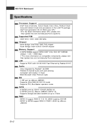
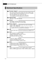
... Celeron Dual-Core processors in the LGA775 package - North Bridge: Intel® P45/ G45/ P43 chipset - Intel® next generation 45 nm Multi-core CPU *(For the latest information about CPU, please visit http://global.msi.com .tw/index.php?func=cpuform) Supported FSB - 1600*(OC)/ 1333/... support RAID 0/ RAID1/ JBOD by ICH10R - Supports storage and data transfers at up to 3 Gb/s RAID - South Bridge: Intel® ICH10/ ICH10R chipset Memory Support - 4 DDR2 DIMMs support DDR2 1066**(OC)/ 800/ 667 SDRAM (240pin / 1.8V / 16GB Max) (**For more inform ation on com patible components, ...
... Celeron Dual-Core processors in the LGA775 package - North Bridge: Intel® P45/ G45/ P43 chipset - Intel® next generation 45 nm Multi-core CPU *(For the latest information about CPU, please visit http://global.msi.com .tw/index.php?func=cpuform) Supported FSB - 1600*(OC)/ 1333/... support RAID 0/ RAID1/ JBOD by ICH10R - Supports storage and data transfers at up to 3 Gb/s RAID - South Bridge: Intel® ICH10/ ICH10R chipset Memory Support - 4 DDR2 DIMMs support DDR2 1066**(OC)/ 800/ 667 SDRAM (240pin / 1.8V / 16GB Max) (**For more inform ation on com patible components, ...

User Guide
Page 15
...enable successful system boot-up, always insert the memory modules into the DIMM1 first. You should always install DDR2 memory modules in different channel DIMM slots. - En-7 English Memory DDR2: DIMM1~4 These DIMM slots are not ...interchangeable with two data bus lines simultaneously. DDR2 memory modules are used for population rules under Dual-Channel mode. 1 DIMM1 DIMM2 DIMM3 DIMM4 2 DIMM1 DIMM2 DIMM3 DIMM4 Installed Empty Important - For more information on compatible components, please visit http://global.msi...
...enable successful system boot-up, always insert the memory modules into the DIMM1 first. You should always install DDR2 memory modules in different channel DIMM slots. - En-7 English Memory DDR2: DIMM1~4 These DIMM slots are not ...interchangeable with two data bus lines simultaneously. DDR2 memory modules are used for population rules under Dual-Channel mode. 1 DIMM1 DIMM2 DIMM3 DIMM4 2 DIMM1 DIMM2 DIMM3 DIMM4 Installed Empty Important - For more information on compatible components, please visit http://global.msi...
User Guide
Page 16
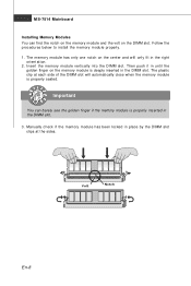
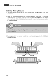
Then push it in until the golden finger on the center and will automatically close when the memory module is deeply inserted in the DIMM slot. The memory module has only one notch on the memory module is properly seated. The plastic clip at each side of the DIMM slot will only fit in... the right ori ent at the sides. Important You can find the notch on the memory module and the volt on . 2. MS-7514 Mainboard Installing Memory Modules You can barely see the golden finger if the memory module is properly inserted in the DIMM slot. 3. Manually check if the...
Then push it in until the golden finger on the center and will automatically close when the memory module is deeply inserted in the DIMM slot. The memory module has only one notch on the memory module is properly seated. The plastic clip at each side of the DIMM slot will only fit in... the right ori ent at the sides. Important You can find the notch on the memory module and the volt on . 2. MS-7514 Mainboard Installing Memory Modules You can barely see the golden finger if the memory module is properly inserted in the DIMM slot. 3. Manually check if the...

User Guide
Page 25
... better system performance. English BIOS Setup This chapter provides basic information on the screen during the system booting up , the 1st line appearing after the memory count is usually in this BIOS was released.
... better system performance. English BIOS Setup This chapter provides basic information on the screen during the system booting up , the 1st line appearing after the memory count is usually in this BIOS was released.
User Manual
Page 8
Hardware Setup 2-1 Quick Components Guide 2-2 CPU (Central Processing Unit 2-3 Memory ...2-7 Power Supply ...2-9 Back Panel ...2-10 Connectors ...2-12 Jumper ...2-19 Slots ...2-20 Chapter 3 BIOS Setup 3-1 Entering Setup ...3-2 The Main Menu ...3-4 Standard CMOS Features 3-6 Advanced BIOS Features 3-9 ...
Hardware Setup 2-1 Quick Components Guide 2-2 CPU (Central Processing Unit 2-3 Memory ...2-7 Power Supply ...2-9 Back Panel ...2-10 Connectors ...2-12 Jumper ...2-19 Slots ...2-20 Chapter 3 BIOS Setup 3-1 Entering Setup ...3-2 The Main Menu ...3-4 Standard CMOS Features 3-6 Advanced BIOS Features 3-9 ...
User Manual
Page 11
... - 2 SATAII ports by JMicron JMB363 1-2 Core and Celeron Dual-Core processors in the LGA775 package - South Bridge: Intel® ICH10/ ICH10R chipset Memory Support - 4 DDR2 DIMMs support DDR2 1066**(OC)/ 800/ 667 SDRAM (240pin / 1.8V / 16GB Max) (**For more information on compatible components, please...Support - m si . t w / i ndex. Supports PCIE LAN 10/100/1000 Fast Ethernet by Realtek® ALC888 - North Bridge: Intel® P45/ G45/ P43 chipset - m si. Chip integrated by Realtek 8111C Audio - Supports storage and data transfers at up to 3 Gb/s RAID - SATA1~6 ...
... - 2 SATAII ports by JMicron JMB363 1-2 Core and Celeron Dual-Core processors in the LGA775 package - South Bridge: Intel® ICH10/ ICH10R chipset Memory Support - 4 DDR2 DIMMs support DDR2 1066**(OC)/ 800/ 667 SDRAM (240pin / 1.8V / 16GB Max) (**For more information on compatible components, please...Support - m si . t w / i ndex. Supports PCIE LAN 10/100/1000 Fast Ethernet by Realtek® ALC888 - North Bridge: Intel® P45/ G45/ P43 chipset - m si. Chip integrated by Realtek 8111C Audio - Supports storage and data transfers at up to 3 Gb/s RAID - SATA1~6 ...

User Manual
Page 21
...different channel DIMM slots. - Please refer to 15+GB (not full 8GB) when each DIMM is not backwards compatible. DDR2 memory modules are used for population rules under Dual-Channel mode. 1 DIMM1 DIMM2 DIMM3 DIMM4 2 DIMM1 DIMM2 DIMM3 DIMM4 Installed Empty Important...DIM M1 first. - For more information on compatible components, please visit http://global.msi.com. To enable successful system boot-up to the following illustrations for installing memory modules. Hardware Setup Memory These DIMM slots are not interchangeable with DDR and the DDR2 standard is installed ...
...different channel DIMM slots. - Please refer to 15+GB (not full 8GB) when each DIMM is not backwards compatible. DDR2 memory modules are used for population rules under Dual-Channel mode. 1 DIMM1 DIMM2 DIMM3 DIMM4 2 DIMM1 DIMM2 DIMM3 DIMM4 Installed Empty Important...DIM M1 first. - For more information on compatible components, please visit http://global.msi.com. To enable successful system boot-up to the following illustrations for installing memory modules. Hardware Setup Memory These DIMM slots are not interchangeable with DDR and the DDR2 standard is installed ...
User Manual
Page 22
... clip at the sides. Then push it in until the golden finger on the center and will automatically close when the memory module is properly seated. Important You can barely see the golden finger if the memory module is deeply inserted in the right orientation. 2. Volt Notch 2-8 Manually check if the...in place by the DIMM slot clips at each side of the DIMM slot will only fit in the DIMM slot. Insert the memory module vertically into the DIMM slot. The memory module has only one notch on the memory module is properly inserted in the DIMM slot. 3. MS-7514 Mainboard Installing...
... clip at the sides. Then push it in until the golden finger on the center and will automatically close when the memory module is properly seated. Important You can barely see the golden finger if the memory module is deeply inserted in the right orientation. 2. Volt Notch 2-8 Manually check if the...in place by the DIMM slot clips at each side of the DIMM slot will only fit in the DIMM slot. Insert the memory module vertically into the DIMM slot. The memory module has only one notch on the memory module is properly inserted in the DIMM slot. 3. MS-7514 Mainboard Installing...

User Manual
Page 37
... RESET button. MS-7514 Mainboard Entering Setup Power on the screen, press key to enter Setup. Upon boot-up, the 1st line appearing after the memory count is usually in this BIOS was released. 3-2
... RESET button. MS-7514 Mainboard Entering Setup Power on the screen, press key to enter Setup. Upon boot-up, the 1st line appearing after the memory count is usually in this BIOS was released. 3-2

User Manual
Page 43
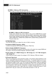
MS-7514 Mainboard System Information Press to enter the sub-menu, and the following screen appears. This sub-menu shows the CPU information, BIOS version and memory status of your system (read only). 3-8
MS-7514 Mainboard System Information Press to enter the sub-menu, and the following screen appears. This sub-menu shows the CPU information, BIOS version and memory status of your system (read only). 3-8
User Manual
Page 45
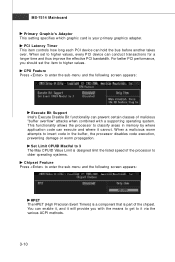
.... PCI Latency Timer This item controls how long each PCI device can execute and where it will provide you should set to insert code in memory by where application code can hold the bus before another takes over. For better PCI performance, you with a supporting operating system. W hen set the item...
.... PCI Latency Timer This item controls how long each PCI device can execute and where it will provide you should set to insert code in memory by where application code can hold the bus before another takes over. For better PCI performance, you with a supporting operating system. W hen set the item...

User Manual
Page 50
...Power Management Setup BIOS Setup Important S3-related functions described in this section are : [S1] The S1 sleep mode is saved to main memory that remains powered while most other hardware components turn off to activate the ACPI (Advanced Configuration and Power Management Interface) Function. ACPI Function This...such as W indows 2000/ XP , you can choose to restore the system when a "wake up" event occurs. 3-15 The information stored in memory will be used to enter the Standby mode in S1(POS) or S3(STR) fashion through the setting of system configuration and open applications/files...
...Power Management Setup BIOS Setup Important S3-related functions described in this section are : [S1] The S1 sleep mode is saved to main memory that remains powered while most other hardware components turn off to activate the ACPI (Advanced Configuration and Power Management Interface) Function. ACPI Function This...such as W indows 2000/ XP , you can choose to restore the system when a "wake up" event occurs. 3-15 The information stored in memory will be used to enter the Standby mode in S1(POS) or S3(STR) fashion through the setting of system configuration and open applications/files...

User Manual
Page 54
... from changing any password. The password typed now will show up to six characters in length, and press . This prevents an unauthorized person from CMOS memory. You may also press to abort the selection and not enter a password. A message will replace any previously set password, just press when you can enter...
... from changing any password. The password typed now will show up to six characters in length, and press . This prevents an unauthorized person from CMOS memory. You may also press to abort the selection and not enter a password. A message will replace any previously set password, just press when you can enter...

User Manual
Page 55
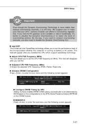
... automatically to enhance the overall performance. 3-20 Usually the Dynamic Overclocking Technology will speed up to make the program run huge amount of CPU and Memory speed. Read-only. W hen the mainboard detects system is designed to adjust the best frequency automatically. D.O.T. It is running programs, and to detect the load...
... automatically to enhance the overall performance. 3-20 Usually the Dynamic Overclocking Technology will speed up to make the program run huge amount of CPU and Memory speed. Read-only. W hen the mainboard detects system is designed to adjust the best frequency automatically. D.O.T. It is running programs, and to detect the load...
User Manual
Page 56
... CAS# Latency automatically to enter the sub-menu and the following screen appears. 3-21 Read-only. We suggest user to make sure that your CPU / memory modules can afford to set the CPU FSB frequency (in MHz). Adjust CPU FSB Frequency (M Hz) This item allows you set the Adjusted CPU FSB...
... CAS# Latency automatically to enter the sub-menu and the following screen appears. 3-21 Read-only. We suggest user to make sure that your CPU / memory modules can afford to set the CPU FSB frequency (in MHz). Adjust CPU FSB Frequency (M Hz) This item allows you set the Adjusted CPU FSB...
User Manual
Page 57
... from empty DIMM and PCI slots to lock up. 3-22 If you are plagued by modulating the pulses so that the spikes of CPU, Memory, FSB and chipset. The Spread Spectrum function reduces the EMI generated by EMI, set to [Enabled], the system will allow you are used to... voltage of the pulses are read only. Spread Spectrum W hen the mainboard's clock generator pulses, the extreme values (spikes) of the current DIMM Memory speed information such as memory type, max bandwidth, manufacture, part number, serial number, SDRAM cycle time, DRAM TCL, DRAM TRCD, DRAM TRP, DRAM TRAS, DRAM TRFC,...
... from empty DIMM and PCI slots to lock up. 3-22 If you are plagued by modulating the pulses so that the spikes of CPU, Memory, FSB and chipset. The Spread Spectrum function reduces the EMI generated by EMI, set to [Enabled], the system will allow you are used to... voltage of the pulses are read only. Spread Spectrum W hen the mainboard's clock generator pulses, the extreme values (spikes) of the current DIMM Memory speed information such as memory type, max bandwidth, manufacture, part number, serial number, SDRAM cycle time, DRAM TCL, DRAM TRCD, DRAM TRP, DRAM TRAS, DRAM TRFC,...

User Manual
Page 83
... Core Center Appendix B Dual Core Center Dual CoreCenter, the most useful and powerful utility that MSI has spent much research and efforts to develop, helps users to monitor or configure the hardware status of MSI Mainboard & MSI Graphics card in this appendix are for software installation. 4. Before you installed. CD-ROM drive ... sure the system has meet the following requirements: 1. Intel Pentium4 / Celeron, AMD Athlon XP/ Sempron or compatible CPU with PCI Express slot. 2. 256MB system memory. 3. The appearance in windows, such as CPU/GPU clock, voltage, fan speed and temperature.
... Core Center Appendix B Dual Core Center Dual CoreCenter, the most useful and powerful utility that MSI has spent much research and efforts to develop, helps users to monitor or configure the hardware status of MSI Mainboard & MSI Graphics card in this appendix are for software installation. 4. Before you installed. CD-ROM drive ... sure the system has meet the following requirements: 1. Intel Pentium4 / Celeron, AMD Athlon XP/ Sempron or compatible CPU with PCI Express slot. 2. 256MB system memory. 3. The appearance in windows, such as CPU/GPU clock, voltage, fan speed and temperature.
User Manual
Page 85
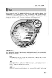
VGA Click VGA button to read current CPU temperature, FSB and CPU clock of the MSI mainboard would be available. DOT Click DOT button to install with the version 8.26 or newer driver)/ V046 or V060 graphics card can activate the ... the function. Introduction: Click each button appearing above to enter sub-menu to make further configuration or to read current GPU temperature, GPU clock and memory clock of this utility, we have to remind you install a graphics card of other brand, only hardware status of mainboard will show below . If you...
VGA Click VGA button to read current CPU temperature, FSB and CPU clock of the MSI mainboard would be available. DOT Click DOT button to install with the version 8.26 or newer driver)/ V046 or V060 graphics card can activate the ... the function. Introduction: Click each button appearing above to enter sub-menu to make further configuration or to read current GPU temperature, GPU clock and memory clock of this utility, we have to remind you install a graphics card of other brand, only hardware status of mainboard will show below . If you...

User Manual
Page 87
... manual overclocking, basically, it is an automatic overclocking function, included in low loading balance, it will speed up the GPU, memory, fan and voltage automatically to make the system run smoother and faster. Dual Core Center DOT (Dynamic OverClocking) Dynamic Overclocking Technology... is still risky. When the motherboard detects that the loading of data, like 3D games or video process, and the motherboard/ graphicd card need to conduct overclocking manually, please do not to enhance the overall ...
... manual overclocking, basically, it is an automatic overclocking function, included in low loading balance, it will speed up the GPU, memory, fan and voltage automatically to make the system run smoother and faster. Dual Core Center DOT (Dynamic OverClocking) Dynamic Overclocking Technology... is still risky. When the motherboard detects that the loading of data, like 3D games or video process, and the motherboard/ graphicd card need to conduct overclocking manually, please do not to enhance the overall ...


