User Guide
Page 2
...; is a registered trademark of Phoenix Technologies Ltd. Revision History Revision V1.0 V1.1 V1.2 V1.3 Revision History First release for G33 First release for P35 First release for P35 Neo2 First release for further guidance. Our products are registered trademarks of purchase or local distributor. Award® is a registered trademark of American Megatrends Inc...
...; is a registered trademark of Phoenix Technologies Ltd. Revision History Revision V1.0 V1.1 V1.2 V1.3 Revision History First release for G33 First release for P35 First release for P35 Neo2 First release for further guidance. Our products are registered trademarks of purchase or local distributor. Award® is a registered trademark of American Megatrends Inc...
User Guide
Page 3
Keep this User's Manual for air convection hence protects the equip- Lay this equipment on it up. 5. DO NOT COVER THE OPENINGS. 6. Always Unplug the Power Cord before setting it . fore connecting the equipment to User's Manual. † The equipment has dropped and damaged. † The equipment has obvious sign of the following situations arises, get it work well or you can not step on a reliable flat surface before inserting any of breakage. 12. All cautions and warnings on the enclosure are for future reference. 3. The openings on the equipment should be...
Keep this User's Manual for air convection hence protects the equip- Lay this equipment on it up. 5. DO NOT COVER THE OPENINGS. 6. Always Unplug the Power Cord before setting it . fore connecting the equipment to User's Manual. † The equipment has dropped and damaged. † The equipment has obvious sign of the following situations arises, get it work well or you can not step on a reliable flat surface before inserting any of breakage. 12. All cautions and warnings on the enclosure are for future reference. 3. The openings on the equipment should be...
User Guide
Page 4
If this device must be determined by turning the equipment off and on a circuit different from that to which can radiate radio frequency energy and, if not installed and used in accordance with the limits for a Class B digital device, pursuant to Part 15 of the FCC Rules. Notice 1 The changes or modifications not expressly approved by one or more of the measures listed below. † Reorient or relocate the receiving antenna. † Increase the separation between the equipment and receiver. † Connect the equipment into an outlet on , the user is encouraged to try to ...
If this device must be determined by turning the equipment off and on a circuit different from that to which can radiate radio frequency energy and, if not installed and used in accordance with the limits for a Class B digital device, pursuant to Part 15 of the FCC Rules. Notice 1 The changes or modifications not expressly approved by one or more of the measures listed below. † Reorient or relocate the receiving antenna. † Increase the separation between the equipment and receiver. † Connect the equipment into an outlet on , the user is encouraged to try to ...

User Guide
Page 5
WEEE (Waste Electrical and Electronic Equipment) Statement v
WEEE (Waste Electrical and Electronic Equipment) Statement v
User Guide
Page 8
Getting Started 1-1 Mainboard Specifications 1-2 Mainboard Layout 1-4 Packing Checklist 1-4 Chapter 2. Hardware Setup 2-1 Quick Components Guide 2-2 CPU (Central Processing Unit 2-2 Memory ...2-7 Power Supply ...2-8 Back Panel ...2-11 Connectors ...2-12 Jumper ...2-19 Button ...2-20 Slots ...2-21 LED Status Indicators 2-23 Chapter 3 BIOS Setup 3-1 Entering Setup ...3-2 The Main Menu ...3-4 Standard CMOS Features 3-6 Advanced BIOS Features 3-9 Integrated Peripherals 3-12 Power Management Setup 3-14 PNP/PCI Configurations 3-17 H/W Monitor ...3-19 Cell Menu ...3-20 Load Fail-...
Getting Started 1-1 Mainboard Specifications 1-2 Mainboard Layout 1-4 Packing Checklist 1-4 Chapter 2. Hardware Setup 2-1 Quick Components Guide 2-2 CPU (Central Processing Unit 2-2 Memory ...2-7 Power Supply ...2-8 Back Panel ...2-11 Connectors ...2-12 Jumper ...2-19 Button ...2-20 Slots ...2-21 LED Status Indicators 2-23 Chapter 3 BIOS Setup 3-1 Entering Setup ...3-2 The Main Menu ...3-4 Standard CMOS Features 3-6 Advanced BIOS Features 3-9 Integrated Peripherals 3-12 Power Management Setup 3-14 PNP/PCI Configurations 3-17 H/W Monitor ...3-19 Cell Menu ...3-20 Load Fail-...
User Guide
Page 9
Hardware Setup A-18 Appendix B Dual Core Center B-1 Activating Dual Core Center B-2 Main ...B-2 DOT (Dynamic OverClocking B-5 Clock ...B-6 Voltage ...B-7 FAN Speed ...B-8 Temperature ...B-9 User Profile ...B-10 Appendix C Intel ICH9R SATA RAID (optional C-1 ICH9R Introduction C-2 BIOS Configuration C-3 Installing Driver ...C-9 Installing Software C-11 RAID Migration Instructions C-15 Degraded RAID Array C-22 ix
Hardware Setup A-18 Appendix B Dual Core Center B-1 Activating Dual Core Center B-2 Main ...B-2 DOT (Dynamic OverClocking B-5 Clock ...B-6 Voltage ...B-7 FAN Speed ...B-8 Temperature ...B-9 User Profile ...B-10 Appendix C Intel ICH9R SATA RAID (optional C-1 ICH9R Introduction C-2 BIOS Configuration C-3 Installing Driver ...C-9 Installing Software C-11 RAID Migration Instructions C-15 Degraded RAID Array C-22 ix
User Guide
Page 10
The P35 Neo2 Series mainboards are based on Intel® P35 & ICH9/ICH9R chipsets for choosing the P35 Neo2 Series (MS-7345 v1.X) ATX mainboard. Getting Started Chapter 1 Getting Started Thank you for optimal system efficiency. Designed to fit the advanced Intel® Core 2 Quad/Core 2 Duo/Pentium/Celeron LGA775 processor, the P35 Neo2 Series deliver a high performance and professional desktop platform solution. 1-1
The P35 Neo2 Series mainboards are based on Intel® P35 & ICH9/ICH9R chipsets for choosing the P35 Neo2 Series (MS-7345 v1.X) ATX mainboard. Getting Started Chapter 1 Getting Started Thank you for optimal system efficiency. Designed to fit the advanced Intel® Core 2 Quad/Core 2 Duo/Pentium/Celeron LGA775 processor, the P35 Neo2 Series deliver a high performance and professional desktop platform solution. 1-1
User Guide
Page 11
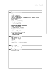
... Fast Ethernet by VIA VT6308 (optional) FDD - 1 floppy port - Support Intel® Yorkfield, Wolfdale (For the latest information about CPU, please visit http://global.msi. North Bridge: Intel® P35 chipset - Meet Microsoft Vista Premium spec - Supports PIO, Bus Master operation mode SATA - Supports 1 FDD with 360KB, 720KB, 1.2MB, 1.44MB and 2.88MB...
... Fast Ethernet by VIA VT6308 (optional) FDD - 1 floppy port - Support Intel® Yorkfield, Wolfdale (For the latest information about CPU, please visit http://global.msi. North Bridge: Intel® P35 chipset - Meet Microsoft Vista Premium spec - Supports PIO, Bus Master operation mode SATA - Supports 1 FDD with 360KB, 720KB, 1.2MB, 1.44MB and 2.88MB...
User Guide
Page 12
... connector - 2 HW OC pinheaders (optional) - 1 front audio pinheader - 1 serial pinheader Slots - 1 PCI Express x16 slot - 2 PCI Express x1 slots - 1 PCI Express x4 slot - 2 PCI slots - ATX (30.5cm X 24.5cm) Mounting - 9 mounting holes 1-3 Support 3.3V/ 5V PCI bus Interface Form Factor -
... connector - 2 HW OC pinheaders (optional) - 1 front audio pinheader - 1 serial pinheader Slots - 1 PCI Express x16 slot - 2 PCI Express x1 slots - 1 PCI Express x4 slot - 2 PCI slots - ATX (30.5cm X 24.5cm) Mounting - 9 mounting holes 1-3 Support 3.3V/ 5V PCI bus Interface Form Factor -
User Guide
Page 13
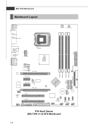
... SYSFAN1 SYSFAN4 PCI_E3 P CI _E 1 JB1 JB2 (o ptional) I/O Chip JCOM1 Codec P CI _E 2 PCI_E4 PCI 1 PCI 2 JAU D1 JC D3 JSL IC1(optional) SPDO Intel P35 SYSFAN3 DI MM _B1 DI MM _B2 DI MM _A1 DI MM _A2 SATA5 SATA3(optional) SATA4 (optional) I CH 9/ II nCtHel9 R SATA6 JCI1 B AT T + IDE1...
... SYSFAN1 SYSFAN4 PCI_E3 P CI _E 1 JB1 JB2 (o ptional) I/O Chip JCOM1 Codec P CI _E 2 PCI_E4 PCI 1 PCI 2 JAU D1 JC D3 JSL IC1(optional) SPDO Intel P35 SYSFAN3 DI MM _B1 DI MM _B2 DI MM _A1 DI MM _A2 SATA5 SATA3(optional) SATA4 (optional) I CH 9/ II nCtHel9 R SATA6 JCI1 B AT T + IDE1...
User Guide
Page 14
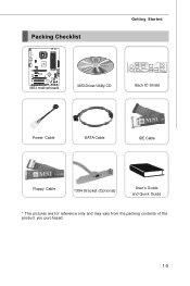
... PC I 2 JAUD1 JCD3 JSLIC1 (op tiona l) SPDO SW1 FDD1 SYSF AN2 JDB1 JFP2 ( optio nal) JUSB 3 JUS B2 J1 394 _1( opt ional ) JFP 1 JUS B 1 MSI motherboard MSI Driver/Utility CD Getting Started Back IO Shield Power Cable SATA Cable IDE Cable Floppy Cable 1394 Bracket (Optional) User's Guide and Quick Guide * The...
... PC I 2 JAUD1 JCD3 JSLIC1 (op tiona l) SPDO SW1 FDD1 SYSF AN2 JDB1 JFP2 ( optio nal) JUSB 3 JUS B2 J1 394 _1( opt ional ) JFP 1 JUS B 1 MSI motherboard MSI Driver/Utility CD Getting Started Back IO Shield Power Cable SATA Cable IDE Cable Floppy Cable 1394 Bracket (Optional) User's Guide and Quick Guide * The...

User Guide
Page 15
Use a grounded wrist strap before handling computer components. For some components, if you with the information about hardware setup procedures. Static electricity may damage the components. 2-1 Hardware Setup Chapter 2 Hardware Setup This chapter provides you install in holding the components and follow the installation procedures. While doing the installation, be careful in the wrong orientation, the components will not work properly.
Use a grounded wrist strap before handling computer components. For some components, if you with the information about hardware setup procedures. Static electricity may damage the components. 2-1 Hardware Setup Chapter 2 Hardware Setup This chapter provides you install in holding the components and follow the installation procedures. While doing the installation, be careful in the wrong orientation, the components will not work properly.
User Guide
Page 17
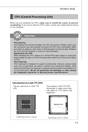
Replaceing the CPU While replacing the CPU, always turn off the ATX power supply or unplug the power supply's power cord from overheating. Overclocking This mainboard is the Pin 1 indicator 2-3 However, please make sure to install the ...
Replaceing the CPU While replacing the CPU, always turn off the ATX power supply or unplug the power supply's power cord from overheating. Overclocking This mainboard is the Pin 1 indicator 2-3 However, please make sure to install the ...
User Guide
Page 18
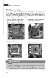
Important 1. Remove the cap from damage. Do not touch the CPU socket pins to install the CPU & cooler correctly. Meanwhile, do not forget to apply some thermal paste on CPU before turning on the top to prevent overheating. Follow the steps below to avoid damaging. 3. W rong installation will cause the damage of your CPU packing. 2-4 Before you are installing the CPU, make sure the CPU has a cooler attached on your CPU cooler is firmly installed before installing the heat sink/cooler fan for better heat dispersion. Confirm if your system. 2. The CPU socket has a ...
Important 1. Remove the cap from damage. Do not touch the CPU socket pins to install the CPU & cooler correctly. Meanwhile, do not forget to apply some thermal paste on CPU before turning on the top to prevent overheating. Follow the steps below to avoid damaging. 3. W rong installation will cause the damage of your CPU packing. 2-4 Before you are installing the CPU, make sure the CPU has a cooler attached on your CPU cooler is firmly installed before installing the heat sink/cooler fan for better heat dispersion. Confirm if your system. 2. The CPU socket has a ...

User Guide
Page 19
Lift the load lever up and open the load plate. 6. After confirming the CPU direction for correct mating, put down the CPU in the socket housing frame. Cover the load plate onto the p ac kage. 2-5 alignment key 7. Note that the alignment keys are matched. If not, take out the CPU with pure vertical motion and reinstall. 8. Be sure to grasp on the edge of the CPU base. Visually inspect if the CPU is seated well into the socket. Hardware Setup 5.
Lift the load lever up and open the load plate. 6. After confirming the CPU direction for correct mating, put down the CPU in the socket housing frame. Cover the load plate onto the p ac kage. 2-5 alignment key 7. Note that the alignment keys are matched. If not, take out the CPU with pure vertical motion and reinstall. 8. Be sure to grasp on the edge of the CPU base. Visually inspect if the CPU is seated well into the socket. Hardware Setup 5.
User Guide
Page 20
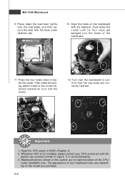
Turn over the mainboard to avoid damaging. 3. MS-7345 Mainboard 9. Then rotate the locking switch (refer to the correct direction marked on it) to fasten the cooler. The appearance of the mainboard. 11. Align the holes on the model you purchase. 2-6 Push down to lock the h ook s . 12. Read the CPU status in this section are correctly inserted. locking switch Important 1. Press the four hooks down the cooler until its four clips get wedged into the holes of your CPU socket pin with the heatsink. Whenever CPU is not installed, always protect your mainboard ...
Turn over the mainboard to avoid damaging. 3. MS-7345 Mainboard 9. Then rotate the locking switch (refer to the correct direction marked on it) to fasten the cooler. The appearance of the mainboard. 11. Align the holes on the model you purchase. 2-6 Push down to lock the h ook s . 12. Read the CPU status in this section are correctly inserted. locking switch Important 1. Press the four hooks down the cooler until its four clips get wedged into the holes of your CPU socket pin with the heatsink. Whenever CPU is not installed, always protect your mainboard ...

User Guide
Page 21
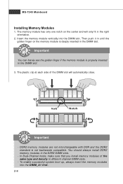
Please refer to the following illustrations for installing memory modules. Hardware Setup Memory These DIMM slots are used for population rules under Dual-Channel mode. 1 DIMM_A1 Installed DIMM_A2 Empty DIMM_B1 DIMM_B2 2 DIMM_A1 DIMM_A2 DIMM_B1 DIMM_B2 3 DIMM_A1 DIMM_A2 DIMM_B1 DIMM_B2 2-7 Channel B in GREEN; Enabling Dual-Channel mode can transmit and receive data with two data bus lines simultaneously. DDR2 240-pin, 1.8V 64x2=128 pin 56x2=112 pin Single-Channel: All DIMMs in GREEN Dual-Channel: Channel A in ORANGE Dual-Channel mode Population Rule In Dual-...
Please refer to the following illustrations for installing memory modules. Hardware Setup Memory These DIMM slots are used for population rules under Dual-Channel mode. 1 DIMM_A1 Installed DIMM_A2 Empty DIMM_B1 DIMM_B2 2 DIMM_A1 DIMM_A2 DIMM_B1 DIMM_B2 3 DIMM_A1 DIMM_A2 DIMM_B1 DIMM_B2 2-7 Channel B in GREEN; Enabling Dual-Channel mode can transmit and receive data with two data bus lines simultaneously. DDR2 240-pin, 1.8V 64x2=128 pin 56x2=112 pin Single-Channel: All DIMMs in GREEN Dual-Channel: Channel A in ORANGE Dual-Channel mode Population Rule In Dual-...
User Guide
Page 22
Important You can barely see the golden finger if the memory module is properly inserted in the DDR2 DIMM slots. - Volt Notch Important - You should always install DDR2 memory modules in the DIMM slot. 3. MS-7345 Mainboard Installing Memory Modules 1. The plastic clip at each side of the same type and density in different channel DIMM slots. - To enable successful system boot-up, always insert the memory modules into the DIMM slot. Insert the memory module vertically into the DIMM _A1 first. 2-8 DDR2 memory modules are not interchangeable with DDR and the DDR2 ...
Important You can barely see the golden finger if the memory module is properly inserted in the DDR2 DIMM slots. - Volt Notch Important - You should always install DDR2 memory modules in the DIMM slot. 3. MS-7345 Mainboard Installing Memory Modules 1. The plastic clip at each side of the same type and density in different channel DIMM slots. - To enable successful system boot-up, always insert the memory modules into the DIMM slot. Insert the memory module vertically into the DIMM _A1 first. 2-8 DDR2 memory modules are not interchangeable with DDR and the DDR2 ...

User Guide
Page 23
...Pin Definition 1 PIN SIGNAL PIN SIGNAL Pin Definition 1 PIN SIGNAL 8 4 POWER1 1 GND 2 GND 3 GND 4 GND 5 +12V 6 +12V 7 +12V 8 +12V 1 2 JPWR1 3 4 5V GND GND 12V Important 1. ATX 12V power connection should be greater than 18A. 4. It can prevent the power cable to touch the heatpipe as you like to use the 20...-pin ATX power supply, please plug your power supply along with pin 1 & pin 13 (refer to the image at the right hand). 13 ATX1 24...
...Pin Definition 1 PIN SIGNAL PIN SIGNAL Pin Definition 1 PIN SIGNAL 8 4 POWER1 1 GND 2 GND 3 GND 4 GND 5 +12V 6 +12V 7 +12V 8 +12V 1 2 JPWR1 3 4 5V GND GND 12V Important 1. ATX 12V power connection should be greater than 18A. 4. It can prevent the power cable to touch the heatpipe as you like to use the 20...-pin ATX power supply, please plug your power supply along with pin 1 & pin 13 (refer to the image at the right hand). 13 ATX1 24...
User Guide
Page 24
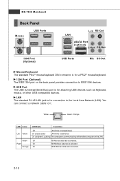
USB Port The USB (Universal Serial Bus) port is selected. Off 10 Mbit/sec data rate is for attaching USB devices such as keyboard, mouse, or other USB-compatible devices. On 100 Mbit/sec data rate is communicating with another computer on the back panel provides connection to IEEE1394 devices. On (brighter & pulsing) The computer is selected. You can connect a network cable to the Local Area Network (LAN). On (steady state) LAN link is not established. Yellow Green / Orange LED Color Left Yellow Green Right Orange LED State Condition Off LAN link is ...
USB Port The USB (Universal Serial Bus) port is selected. Off 10 Mbit/sec data rate is for attaching USB devices such as keyboard, mouse, or other USB-compatible devices. On 100 Mbit/sec data rate is communicating with another computer on the back panel provides connection to IEEE1394 devices. On (brighter & pulsing) The computer is selected. You can connect a network cable to the Local Area Network (LAN). On (steady state) LAN link is not established. Yellow Green / Orange LED Color Left Yellow Green Right Orange LED State Condition Off LAN link is ...
