
User Guide
Page 8
... Safety Instructions iii FCC-B Radio Frequency Interference Statement iv WEEE (Waste Electrical and Electronic Equipment) Statement v English ...En-1 Specifications ...En-2 Central Processing Unit: CPU En-5 Memory ...En-7 Connectors, Jumpers, Slots En-9 Back Panel ...En-18 LED Status Indicators En-21 BIOS Setup ...En-23 Software Information En-27 Deutsch ...De-1 Spezifikationen...
... Safety Instructions iii FCC-B Radio Frequency Interference Statement iv WEEE (Waste Electrical and Electronic Equipment) Statement v English ...En-1 Specifications ...En-2 Central Processing Unit: CPU En-5 Memory ...En-7 Connectors, Jumpers, Slots En-9 Back Panel ...En-18 LED Status Indicators En-21 BIOS Setup ...En-23 Software Information En-27 Deutsch ...De-1 Spezifikationen...

User Guide
Page 10
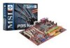
c om . North Bridge: Intel® P35 chipset - Chip integrated by ICH9R En-2 About ports of SATAII please check Intel website and based on PCB version. - Supports Intel Martix Storage Technology (AHCI + .... p hp? Meet Microsoft Vista Premium spec - m s i. t w / in the LGA775 package - Supports Ultra DMA 66/100/133 m ode - South Bridge: Intel® ICH9/ICH9R Base chipset Memory Support - Supports PCIE LAN 10/100/1000 Fast Ethernet by Marvell 88SE6111 - Supports storage and data transfers at up to 300 MB/s RAID (optional) - MS...
c om . North Bridge: Intel® P35 chipset - Chip integrated by ICH9R En-2 About ports of SATAII please check Intel website and based on PCB version. - Supports Intel Martix Storage Technology (AHCI + .... p hp? Meet Microsoft Vista Premium spec - m s i. t w / in the LGA775 package - Supports Ultra DMA 66/100/133 m ode - South Bridge: Intel® ICH9/ICH9R Base chipset Memory Support - Supports PCIE LAN 10/100/1000 Fast Ethernet by Marvell 88SE6111 - Supports storage and data transfers at up to 300 MB/s RAID (optional) - MS...

User Guide
Page 15
...definition : DIMM slot(s) on Channel B are m arked in Purple color. 40x2=80 pin 52x2=104 pin 3 DDR2 Specification : 240-pin, 1.8v. English Memory 2 DDR Specification : 184-pin, 2.5v. Single channel definition : All DIMM slots are GREEN color. En-7 Single channel definition : All DIMM slots are ...of the same type and density in the DDR2 DIMM slots. - You should always install DDR2 memory modules in different channel DIMM slots. - To enable successful system boot-up, always insert the memory modules into the DIMM1 first. DIMM slot(s) on Channel A are m arked in Orange color...
...definition : DIMM slot(s) on Channel B are m arked in Purple color. 40x2=80 pin 52x2=104 pin 3 DDR2 Specification : 240-pin, 1.8v. English Memory 2 DDR Specification : 184-pin, 2.5v. Single channel definition : All DIMM slots are GREEN color. En-7 Single channel definition : All DIMM slots are ...of the same type and density in the DDR2 DIMM slots. - You should always install DDR2 memory modules in different channel DIMM slots. - To enable successful system boot-up, always insert the memory modules into the DIMM1 first. DIMM slot(s) on Channel A are m arked in Orange color...

User Guide
Page 16
... will only fit in the right ori ent at each side of the DIMM slot will automatically close. Volt Notch En-8 The memory m odules has only one notch on the memory module is properly inserted in the DIMM slot. Insert the m em ory module vertically into the DIMM slot. Important You can... find the notch on the memory modules and the volt on . 2. The plastic clip at i on the DIMM slots whether DDR or DDR2. Follow the procedures below to install the m emory...
... will only fit in the right ori ent at each side of the DIMM slot will automatically close. Volt Notch En-8 The memory m odules has only one notch on the memory module is properly inserted in the DIMM slot. Insert the m em ory module vertically into the DIMM slot. Important You can... find the notch on the memory modules and the volt on . 2. The plastic clip at i on the DIMM slots whether DDR or DDR2. Follow the procedures below to install the m emory...

User Guide
Page 22
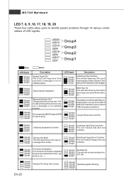
...initialize Floppy Drive and 4 controller. 2 BootAttempt 4 This will start showing information 3 4 about logo, processor brand name, etc... 1 3 Memory Detection Test 2 Testing onboard memory size. Then, detect and initializethe video adapter. 1 2 EarlyChipset Initialization 3 4 BIOS Sign On 1 2 This will set low stack and ...boot via INT 19h. 2 4 Operating System Booting Testing Base and Extended Memory 2 Testing base memory from 240K to 4 640K and extended memory above 1MB using various patterns. 1 3 2 Decompressing BIOS image to RAM 1 4 for you ...
...initialize Floppy Drive and 4 controller. 2 BootAttempt 4 This will start showing information 3 4 about logo, processor brand name, etc... 1 3 Memory Detection Test 2 Testing onboard memory size. Then, detect and initializethe video adapter. 1 2 EarlyChipset Initialization 3 4 BIOS Sign On 1 2 This will set low stack and ...boot via INT 19h. 2 4 Operating System Booting Testing Base and Extended Memory 2 Testing base memory from 240K to 4 640K and extended memory above 1MB using various patterns. 1 3 2 Decompressing BIOS image to RAM 1 4 for you ...

User Guide
Page 25
... the PCI Express interface expansion card. The PCI Express x 16 supports up to 2.0 GB/s transfer rate. The PCI Express x 1 supports up to directly access m ain memory.
... the PCI Express interface expansion card. The PCI Express x 16 supports up to 2.0 GB/s transfer rate. The PCI Express x 1 supports up to directly access m ain memory.
User Guide
Page 30
... is damaged or not installed properly. Then, detect and initializethe video adapter. Group4 Group3 Group2 Group1 Decompressing BIOS image to 640K and extended memory above 1MB using various patterns. MS-7345 Mainboard LED 7, 8, 9 ,10, 17, 18, 19, 20 These four LEDs allow users...This will start showing information about logo, processor brand name, etc... Group4 Group3 Group2 Group1 BootAttempt This will hang if the memory module is damaged or not installed properly. Group4 Group3 Group2 Group1 Assign Resources to identify system problems through 16 various combinations of...
... is damaged or not installed properly. Then, detect and initializethe video adapter. Group4 Group3 Group2 Group1 Decompressing BIOS image to 640K and extended memory above 1MB using various patterns. MS-7345 Mainboard LED 7, 8, 9 ,10, 17, 18, 19, 20 These four LEDs allow users...This will start showing information about logo, processor brand name, etc... Group4 Group3 Group2 Group1 BootAttempt This will hang if the memory module is damaged or not installed properly. Group4 Group3 Group2 Group1 Assign Resources to identify system problems through 16 various combinations of...

User Guide
Page 31
... you to run the Setup program when: * An error message appears on the screen during the system booting up , the 1st line appearing after the memory count is usually in this BIOS was released. Therefore, the description may need to run BIOS SETUP. * You want to the date this chapter are...
... you to run the Setup program when: * An error message appears on the screen during the system booting up , the 1st line appearing after the memory count is usually in this BIOS was released. Therefore, the description may need to run BIOS SETUP. * You want to the date this chapter are...


