User Manual
Page 8
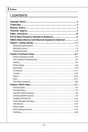
... Revision History ii Technical Support ii Safety Instructions iii FCC-B Radio Frequency Interference Statement iv WEEE (Waste Electrical and Electronic Equipment) Statement v Chapter 1 Getting Started 1-1 Mainboard Specifications 1-2 Mainboard Layout 1-4 Packing Checklist 1-5 Chapter 2 Hardware Setup 2-1 Quick Components Guide 2-2 CPU (Central Processing Unit 2-3 Memory 2-6 Power Supply 2-8 Back Panel 2-9 Connectors 2-11 Jumpers 2-19 Switch 2-20...
... Revision History ii Technical Support ii Safety Instructions iii FCC-B Radio Frequency Interference Statement iv WEEE (Waste Electrical and Electronic Equipment) Statement v Chapter 1 Getting Started 1-1 Mainboard Specifications 1-2 Mainboard Layout 1-4 Packing Checklist 1-5 Chapter 2 Hardware Setup 2-1 Quick Components Guide 2-2 CPU (Central Processing Unit 2-3 Memory 2-6 Power Supply 2-8 Back Panel 2-9 Connectors 2-11 Jumpers 2-19 Switch 2-20...
User Manual
Page 10
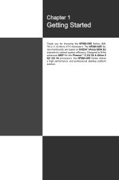
The NF980-G65 Series mainboards are based on NVIDIA® nForce 980A SLI chipsets for choosing the NF980-G65 Series (MS7612 v1.X) Micro ATX mainboard. Designed to fit the advanced AMD® 64 bits PhenomTM II X3/ X4 & Athlon II X2/ X3/ X4 processors, the NF980-G65 Series deliver a high performance and professional desktop platform solution. 1-1-1 Chapter 1 Getting Started Thank you for optimal system efficiency.
The NF980-G65 Series mainboards are based on NVIDIA® nForce 980A SLI chipsets for choosing the NF980-G65 Series (MS7612 v1.X) Micro ATX mainboard. Designed to fit the advanced AMD® 64 bits PhenomTM II X3/ X4 & Athlon II X2/ X3/ X4 processors, the NF980-G65 Series deliver a high performance and professional desktop platform solution. 1-1-1 Chapter 1 Getting Started Thank you for optimal system efficiency.
User Manual
Page 11
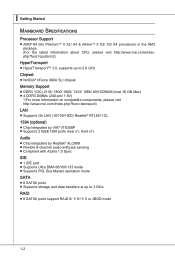
... 800 SDRAM (total 16 GB Max) ■ 4 DDR3 DIMMs (240-pin/ 1.5V) *(For more information on compatible components, please visit http://www.msi.com/index.php?func=testreport) LAN ■ Supports Gb LAN (10/100/1000) Realtek® RTL8211CL 1394 (optional) ■ Chip integrated by VIA&#...; Supports storage and data transfers at up to 3 Gb/s RAID ■ 6 SATAII ports support RAID 0/ 1/ 0+1/ 5 or JBOD mode 1-2 ▍ Getting Started Mainboard Specifications Processor Support ■ AMD® 64 bits PhenomTM II X3/ X4 & AthlonTM II X2/ X3/ X4 processors in the AM3 package. (For the latest...
... 800 SDRAM (total 16 GB Max) ■ 4 DDR3 DIMMs (240-pin/ 1.5V) *(For more information on compatible components, please visit http://www.msi.com/index.php?func=testreport) LAN ■ Supports Gb LAN (10/100/1000) Realtek® RTL8211CL 1394 (optional) ■ Chip integrated by VIA&#...; Supports storage and data transfers at up to 3 Gb/s RAID ■ 6 SATAII ports support RAID 0/ 1/ 0+1/ 5 or JBOD mode 1-2 ▍ Getting Started Mainboard Specifications Processor Support ■ AMD® 64 bits PhenomTM II X3/ X4 & AthlonTM II X2/ X3/ X4 processors in the AM3 package. (For the latest...
User Manual
Page 13
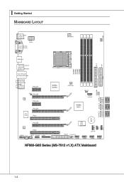
▍ Getting Started Mainboard Layout NF980-G65 Series (MS-7612 v1.X) ATX Mainboard 1-4
▍ Getting Started Mainboard Layout NF980-G65 Series (MS-7612 v1.X) ATX Mainboard 1-4

User Manual
Page 14
Packing Checklist MS-7612 MSI mainboard MSI Driver/Utility DVD SATA Cable (Optional) Power Cable USB Bracket (Optional) Standard Cable for IDE Devices Back IO Shield User's Guide * The pictures are for reference only and may vary from the packing contents of the product you could search the product web page and find details on our web address http://www.msi.com/index.php 1-5 If you need to purchase accessories and request the part numbers, you purchased.
Packing Checklist MS-7612 MSI mainboard MSI Driver/Utility DVD SATA Cable (Optional) Power Cable USB Bracket (Optional) Standard Cable for IDE Devices Back IO Shield User's Guide * The pictures are for reference only and may vary from the packing contents of the product you could search the product web page and find details on our web address http://www.msi.com/index.php 1-5 If you need to purchase accessories and request the part numbers, you purchased.
User Manual
Page 18
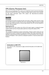
... beyond product specifications is designed to AM3 CPU The surface of CPU. For the latest information about CPU, please visit http://www.msi.com/index. However, please make sure your dealer before turning on it for better heat dispersion. Remember to operate beyond product specifications... tape) between the CPU and the heatsink to enhance heat dissipation. Replacing the CPU While replacing the CPU, always turn off the ATX power supply or unplug the power supply's power cord from overheating. Introduction to support overclocking. MS-7612 CPU (Central Processing Unit) When...
... beyond product specifications is designed to AM3 CPU The surface of CPU. For the latest information about CPU, please visit http://www.msi.com/index. However, please make sure your dealer before turning on it for better heat dispersion. Remember to operate beyond product specifications... tape) between the CPU and the heatsink to enhance heat dissipation. Replacing the CPU While replacing the CPU, always turn off the ATX power supply or unplug the power supply's power cord from overheating. Introduction to support overclocking. MS-7612 CPU (Central Processing Unit) When...
User Manual
Page 19
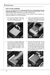
...with your fingers pressing tightly on CPU before installing the heat sink/cooler fan for the gold arrow of the CPU to your CPU & mainboard 1. ▍ Hardware Setup CPU & Cooler Installation When you are installing the CPU, make sure the CPU is correctly installed, the pins...Pull the lever sideways away from the socket. Press the CPU down firmly into the socket. 2-4 Please note that any violation of your mainboard. 4. Make sure to raise the lever up to prevent overheating. Wrong installation will cause the damage of the correct installation procedures may cause ...
...with your fingers pressing tightly on CPU before installing the heat sink/cooler fan for the gold arrow of the CPU to your CPU & mainboard 1. ▍ Hardware Setup CPU & Cooler Installation When you are installing the CPU, make sure the CPU is correctly installed, the pins...Pull the lever sideways away from the socket. Press the CPU down firmly into the socket. 2-4 Please note that any violation of your mainboard. 4. Make sure to raise the lever up to prevent overheating. Wrong installation will cause the damage of the correct installation procedures may cause ...
User Manual
Page 20
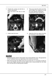
... on the top of your fingers, because once the Safety Hook is necessary to keep an eye on the mainboard. Hook one end of the clip to the CPU fan connector on your mainboard may vary depending on the model you purchase. • While disconnecting the Safety Hook from the fixed bolt... end of the clip to fasten the cooling set onto the retention mechanism. Attach the CPU Fan cable to hook first. 6. MS-7612 5. Important • Mainboard photos shown in this section are for demonstration only.
... on the top of your fingers, because once the Safety Hook is necessary to keep an eye on the mainboard. Hook one end of the clip to the CPU fan connector on your mainboard may vary depending on the model you purchase. • While disconnecting the Safety Hook from the fixed bolt... end of the clip to fasten the cooling set onto the retention mechanism. Attach the CPU Fan cable to hook first. 6. MS-7612 5. Important • Mainboard photos shown in this section are for demonstration only.

User Manual
Page 23
... power supply firmly into the connector. ▍ Hardware Setup Power Supply ATX 24-pin Power Connector: ATX1 This connector allows you like to use the 20-pin ATX power supply as you to ensure stable operation of the mainboard. • Power supply of the power supply is highly recommended for ...system stability. 2-8 You may use the 20-pin ATX power supply, please plug your power supply along with ...
... power supply firmly into the connector. ▍ Hardware Setup Power Supply ATX 24-pin Power Connector: ATX1 This connector allows you like to use the 20-pin ATX power supply as you to ensure stable operation of the mainboard. • Power supply of the power supply is highly recommended for ...system stability. 2-8 You may use the 20-pin ATX power supply, please plug your power supply along with ...
User Manual
Page 28
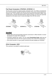
... SYSFAN1/ 2 3.S2.e+1n1.sG2orVround SYSFAN3 3.N2.o+1U1.G2srVeound Important • Please refer to the actual CPU temperature. • Fan cooler set with +12V. If the mainboard has a System Hardware Monitor chipset on-board, you must use a specially designed fan with speed sensor to GND. the black wire is provided for proper...
... SYSFAN1/ 2 3.S2.e+1n1.sG2orVround SYSFAN3 3.N2.o+1U1.G2srVeound Important • Please refer to the actual CPU temperature. • Fan cooler set with +12V. If the mainboard has a System Hardware Monitor chipset on-board, you must use a specially designed fan with speed sensor to GND. the black wire is provided for proper...
User Manual
Page 34
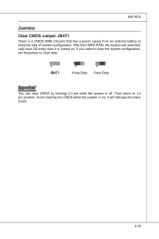
MS-7612 Jumpers Clear CMOS Jumper: JBAT1 There is turned on ; Avoid clearing the CMOS while the system is off. If you want to clear the system configuration, set the jumper to clear data. 1 JBAT1 1 Keep Data 1 Clear Data Important You can automatically boot OS every time it will damage the mainboard. 2-19 Then return to keep the data of system configuration. With the CMOS RAM, the system can clear CMOS by shorting 2-3 pin while the system is on . it is a CMOS RAM onboard that has a power supply from an external battery to 1-2 pin position.
MS-7612 Jumpers Clear CMOS Jumper: JBAT1 There is turned on ; Avoid clearing the CMOS while the system is off. If you want to clear the system configuration, set the jumper to clear data. 1 JBAT1 1 Keep Data 1 Clear Data Important You can automatically boot OS every time it will damage the mainboard. 2-19 Then return to keep the data of system configuration. With the CMOS RAM, the system can clear CMOS by shorting 2-3 pin while the system is on . it is a CMOS RAM onboard that has a power supply from an external battery to 1-2 pin position.

User Manual
Page 35
...Increase 20% speed of switch. Follow the instructions below to set the switch to default setting. 2-20 ▍ Hardware Setup Switch This mainboard provides the following switch for you power off the system before setting the switch. • When overclocking cause system instability or crash during...Overclock FSB Switch: OCSWITCH1 You can overclock the FSB to set the computer's function. This section will explain how to change your mainboard's function through the use of FSB Important • Make sure that you to increase the processor frequency by changing the switch. Please...
...Increase 20% speed of switch. Follow the instructions below to set the switch to default setting. 2-20 ▍ Hardware Setup Switch This mainboard provides the following switch for you power off the system before setting the switch. • When overclocking cause system instability or crash during...Overclock FSB Switch: OCSWITCH1 You can overclock the FSB to set the computer's function. This section will explain how to change your mainboard's function through the use of FSB Important • Make sure that you to increase the processor frequency by changing the switch. Please...

User Manual
Page 37
... a single graphics card. SLI Video Link Card Important • The photos shown in tandem within a system to achieve up to twice the performance of your mainboard may vary depending on the model you purchase. • If you intend to install only ONE graphics card, make sure that the graphics card is...
... a single graphics card. SLI Video Link Card Important • The photos shown in tandem within a system to achieve up to twice the performance of your mainboard may vary depending on the model you purchase. • If you intend to install only ONE graphics card, make sure that the graphics card is...
User Manual
Page 39
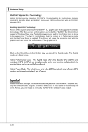
... based on NVIDIA®'s industry-leading SLI technology, delivers multi-GPU benefits when an NVIDIA® mainboard GPU is combined with the graphic card and boost the performance of mainboard) will share the rendering load with an NVIDIA® discrete GPU. The Hybrid modes are simultaneously ...active and working collaboratively to the onboard video output. 2-24 The hybrid mode where the discrete GPU (dGPU) and mainboard GPU (mGPU) are listed below. Important Please note that the system is in the System tray can select the Hybird mode. Enabling Hybrid...
... based on NVIDIA®'s industry-leading SLI technology, delivers multi-GPU benefits when an NVIDIA® mainboard GPU is combined with the graphic card and boost the performance of mainboard) will share the rendering load with an NVIDIA® discrete GPU. The Hybrid modes are simultaneously ...active and working collaboratively to the onboard video output. 2-24 The hybrid mode where the discrete GPU (dGPU) and mainboard GPU (mGPU) are listed below. Important Please note that the system is in the System tray can select the Hybird mode. Enabling Hybrid...
User Manual
Page 46
... the BIOS vendor for stable system performance. ▶ Load Optimized Defaults Use this menu to load the default values set by the mainboard manufacturer specifically for optimal performance of the mainboard. ▶ Save & Exit Setup Save changes to CMOS and exit setup. ▶ Exit Without Saving Abandon all changes and exit setup...
... the BIOS vendor for stable system performance. ▶ Load Optimized Defaults Use this menu to load the default values set by the mainboard manufacturer specifically for optimal performance of the mainboard. ▶ Save & Exit Setup Save changes to CMOS and exit setup. ▶ Exit Without Saving Abandon all changes and exit setup...
User Manual
Page 48
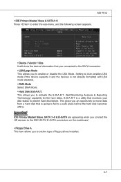
... drives installed. 3-7 Important IDE Primary Master/ Slave, SATA 1~5 & E-SATA are appearing when you connect the HD devices to the IDE/ SATA/ E-SATA connectors on the mainboard. ▶ Floppy Drive A This item allows you an opportunity to enable or disable the LBA Mode. This allows you to move data from a hard disk...
... drives installed. 3-7 Important IDE Primary Master/ Slave, SATA 1~5 & E-SATA are appearing when you connect the HD devices to the IDE/ SATA/ E-SATA connectors on the mainboard. ▶ Floppy Drive A This item allows you an opportunity to enable or disable the LBA Mode. This allows you to move data from a hard disk...
User Manual
Page 58
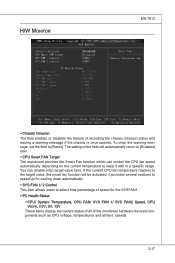
... the warning message, set the field to select how percentage of the field will automatically return to [Enabled] later. ▶ CPU Smart FAN Target The mainboard provides the Smart Fan function which can enable a fan target value here. You can control the CPU fan speed automatically depending on the current temperature...
... the warning message, set the field to select how percentage of the field will automatically return to [Enabled] later. ▶ CPU Smart FAN Target The mainboard provides the Smart Fan function which can enable a fan target value here. You can control the CPU fan speed automatically depending on the current temperature...
User Manual
Page 59
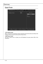
▍ BIOS Setup Green Power ▶ CPU Phase Control When set to [Auto], the hardware will auto adjust the CPU power phase according to the loading of CPU to reach the best power saving function. ▶ LED Power Control This item is used to turn on (Auto)/ turn off (Disabled) the power phase LEDs of the mainboard. 3-18
▍ BIOS Setup Green Power ▶ CPU Phase Control When set to [Auto], the hardware will auto adjust the CPU power phase according to the loading of CPU to reach the best power saving function. ▶ LED Power Control This item is used to turn on (Auto)/ turn off (Disabled) the power phase LEDs of the mainboard. 3-18

User Manual
Page 70
... and pressing Enter loads the default factory settings for optimal performance of the BIOS settings to restore all of the mainboard. The Fail-Safe Defaults are the default values set by the mainboard manufacturer specifically for optimal system performance. 3-29 When you select Load Fail-Safe Defaults, a message as below appears: Selecting...
... and pressing Enter loads the default factory settings for optimal performance of the BIOS settings to restore all of the mainboard. The Fail-Safe Defaults are the default values set by the mainboard manufacturer specifically for optimal system performance. 3-29 When you select Load Fail-Safe Defaults, a message as below appears: Selecting...

User Manual
Page 93
A-22 ▍ Realtek Audio ■ 8-Channel Mode for Stereo-Speaker Output 1] Line In 2] Line Out (Front channels) 3] MIC 4] Line Out (Rear channels) 5] Line Out (Center and Subwoofer channel) 6] Line Out (Side channels) Important To enable 7.1 channel audio-out function on Windows Vista operating system, you have to install the Realtek Audio Driver. Or, the mainboard will support 5.1 channel audio-out only.
A-22 ▍ Realtek Audio ■ 8-Channel Mode for Stereo-Speaker Output 1] Line In 2] Line Out (Front channels) 3] MIC 4] Line Out (Rear channels) 5] Line Out (Center and Subwoofer channel) 6] Line Out (Side channels) Important To enable 7.1 channel audio-out function on Windows Vista operating system, you have to install the Realtek Audio Driver. Or, the mainboard will support 5.1 channel audio-out only.


