User Guide
Page 5
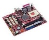
...JCI1 JFP1 SW2 IDE 2 IDE 1 1 Designed to fit the advanced AMD ® AthlonTM/AthlonTM XP/DuronTM processors in 462 pin package, the KM4M-V/KM4AM-V/KM3M-V Series delivers a high performance and professional desktop platform solution. Layout Top : mouse Bottom: keyboard SOCKET 462 FANCPU1 CONN 1 FDD ...Out Mic COM2 Winbond W83697HF AGP Slot PCI Slot 1 BIOS JCD1 VIA VT1617A PCI Slot 2 PCI Slot 3 JAUD1 VIA VT8237 SATA2 (for KM400/ KM400A) SATA1 (for optimal system efficiency. Introduction Thank you for choosing the KM4M-V/KM4AM-V/KM3M-V Series (MS-7061 v1.X) micro ATX mainboard.
...JCI1 JFP1 SW2 IDE 2 IDE 1 1 Designed to fit the advanced AMD ® AthlonTM/AthlonTM XP/DuronTM processors in 462 pin package, the KM4M-V/KM4AM-V/KM3M-V Series delivers a high performance and professional desktop platform solution. Layout Top : mouse Bottom: keyboard SOCKET 462 FANCPU1 CONN 1 FDD ...Out Mic COM2 Winbond W83697HF AGP Slot PCI Slot 1 BIOS JCD1 VIA VT1617A PCI Slot 2 PCI Slot 3 JAUD1 VIA VT8237 SATA2 (for KM400/ KM400A) SATA1 (for optimal system efficiency. Introduction Thank you for choosing the KM4M-V/KM4AM-V/KM3M-V Series (MS-7061 v1.X) micro ATX mainboard.
User Guide
Page 7
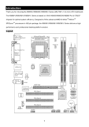
VIA1617A codec. - 5.1 channel AC'97 software Audio. The mainboard BIOS provides "Plug & Play" BIOS which detects the peripheral devices and expansion cards of the board automatically. ! Mounting ! 6 mounting holes. Supports PS2 Keyboard/Mouse. ! LAN -...voltage. 3 Audio - - 2 SATA connectors (for KM400/KM400A only) - 8 USB 2.0 ports (Rear * 4/ Front * 4). - 3 audio (Line-In/Line-Out/Mic) ports. - Micro-ATX Form Factor: 245 mm x 192mm. VRAM size maximum is to 64MB. (Optional). ! The mainboard provides a Desktop Management Interface (DMI) function that records your mainboard specifications...
VIA1617A codec. - 5.1 channel AC'97 software Audio. The mainboard BIOS provides "Plug & Play" BIOS which detects the peripheral devices and expansion cards of the board automatically. ! Mounting ! 6 mounting holes. Supports PS2 Keyboard/Mouse. ! LAN -...voltage. 3 Audio - - 2 SATA connectors (for KM400/KM400A only) - 8 USB 2.0 ports (Rear * 4/ Front * 4). - 3 audio (Line-In/Line-Out/Mic) ports. - Micro-ATX Form Factor: 245 mm x 192mm. VRAM size maximum is to 64MB. (Optional). ! The mainboard provides a Desktop Management Interface (DMI) function that records your mainboard specifications...
User Guide
Page 11
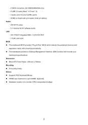
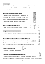
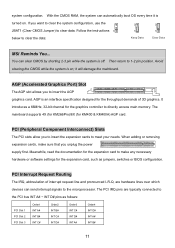
..., 1.2M, 1.44M and 2.88M floppy disk types. R CD-In Connector: JCD1 GND The connector is used to provide power to an ATX power supply. Chassis Intrusion Switch Connector: JCI1 (Optional) This connector is inserted in the proper orientation and the pins are installed properly to ensure... is connected to the connectors, always 7 If the GND 2 CINTRU 1 Chassis is suggested. 3.3V ATX 20-Pin Power Connector: CONN1 -12V GND This connector allows you must enter the BIOS setting and clear the status. They support three-pin head connector. The system will be caused. A ...
..., 1.2M, 1.44M and 2.88M floppy disk types. R CD-In Connector: JCD1 GND The connector is used to provide power to an ATX power supply. Chassis Intrusion Switch Connector: JCI1 (Optional) This connector is inserted in the proper orientation and the pins are installed properly to ensure... is connected to the connectors, always 7 If the GND 2 CINTRU 1 Chassis is suggested. 3.3V ATX 20-Pin Power Connector: CONN1 -12V GND This connector allows you must enter the BIOS setting and clear the status. They support three-pin head connector. The system will be caused. A ...
User Guide
Page 15
... for the throughput demands of interrupt request line and pronounced I-R-Q, are typically connected to clear the data: Keep Data Clear Data MSI Reminds You... The PCI IRQ pins are hardware lines over which devices can automatically boot OS every time it will damage the ...) to insert the AGP graphics card. Follow the instructions 1 1 1 below to the PCI bus INT A# ~ INT D# pins as jumpers, switches or BIOS configuration. Then return to the microprocessor. it is an interface specification designed for the expansion card, such as follows: PCI Slot 1 PCI Slot 2 PCI Slot...
... for the throughput demands of interrupt request line and pronounced I-R-Q, are typically connected to clear the data: Keep Data Clear Data MSI Reminds You... The PCI IRQ pins are hardware lines over which devices can automatically boot OS every time it will damage the ...) to insert the AGP graphics card. Follow the instructions 1 1 1 below to the PCI bus INT A# ~ INT D# pins as jumpers, switches or BIOS configuration. Then return to the microprocessor. it is an interface specification designed for the expansion card, such as follows: PCI Slot 1 PCI Slot 2 PCI Slot...
User Guide
Page 16
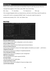
BIOS Setup Power on the screen, press key to change the values in the chipset registers and optimize your system supports PnP/PCI. Main Page Standard ...: Network boot TAB: Logo If the message disappears before you respond and you still wish to setup the items of Award special enhanced features. Advanced BIOS Features Use this menu to enter Setup.
BIOS Setup Power on the screen, press key to change the values in the chipset registers and optimize your system supports PnP/PCI. Main Page Standard ...: Network boot TAB: Logo If the message disappears before you respond and you still wish to setup the items of Award special enhanced features. Advanced BIOS Features Use this menu to enter Setup.

User Guide
Page 17
Set Supervisor Password Use this menu to set Supervisor Password. Set User Password Use this menu to set User Password. Use this menu to load factory default settings into the BIOS for the best system performance, but the system stability may be affected. Save & Exit Setup Save changes to load the BIOS values for stable system performance operations. Load Optimized Defaults Use this menu to CMOS and exit setup. Exit Without Saving Abandon all changes and exit setup. 13
Set Supervisor Password Use this menu to set Supervisor Password. Set User Password Use this menu to set User Password. Use this menu to load factory default settings into the BIOS for the best system performance, but the system stability may be affected. Save & Exit Setup Save changes to load the BIOS values for stable system performance operations. Load Optimized Defaults Use this menu to CMOS and exit setup. Exit Without Saving Abandon all changes and exit setup. 13
User Guide
Page 18
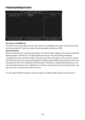
... (turn off) clocks from empty PCI slots to [Enabled] for optimal system stability and performance. For the complete BIOS introduction and setup, please visit MSI website at [Disabled] for EMI reduction. Remember to disable Spread Spectrum if you are reduced to flatter curves. If...electromagnetic interference (EMI). Frequency/Voltage Control Auto Detect PCI/DIMM Clk This item is used to lock up. Spread Spectrum When the motherboard's clock generator pulses, the extreme values (spikes) of the pulses are overclocking because even a slight jitter can introduce a temporary boost...
... (turn off) clocks from empty PCI slots to [Enabled] for optimal system stability and performance. For the complete BIOS introduction and setup, please visit MSI website at [Disabled] for EMI reduction. Remember to disable Spread Spectrum if you are reduced to flatter curves. If...electromagnetic interference (EMI). Frequency/Voltage Control Auto Detect PCI/DIMM Clk This item is used to lock up. Spread Spectrum When the motherboard's clock generator pulses, the extreme values (spikes) of the pulses are overclocking because even a slight jitter can introduce a temporary boost...
User Guide
Page 51
VIA1617A 5.1 声道 AC'97 LAN - VIA VT8237 集成于 MAC + VIA 6103 PHY - 1 个 RJ45 LAN 插孔 BIOS BIOS 提供"Plug & Play DMI Micro-ATX 245 mm x 192mm 6 PS2 VRAM 64MB CPU 47 - 1 SPP/EPP/ECP 模式 - 2 个 SATA KM400 & KM400A) - 8 个 USB 2.0 4/ 前置* 4) - 3 Line-In/Line-Out/Mic Intel COM2 音频 -
VIA1617A 5.1 声道 AC'97 LAN - VIA VT8237 集成于 MAC + VIA 6103 PHY - 1 个 RJ45 LAN 插孔 BIOS BIOS 提供"Plug & Play DMI Micro-ATX 245 mm x 192mm 6 PS2 VRAM 64MB CPU 47 - 1 SPP/EPP/ECP 模式 - 2 个 SATA KM400 & KM400A) - 8 个 USB 2.0 4/ 前置* 4) - 3 Line-In/Line-Out/Mic Intel COM2 音频 -
User Guide
Page 55
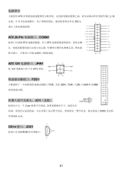
电源供应 ATX 300 瓦 11 1 3.3V -12V 3.3V 3.3V GND GND PS_ON 5V ATX 20-Pin CONN1 GND GND GND 5V ATX ATX GND GND -5V PW_OK 5V 5V_SB 5V 12V 20 10 ATX 12V JPW1 12 GND GND 此 12V CPU 供电。 12V 12V 34 FDD1 FDD,支持 360K、720K、1.2M、1.44M 和 2.88M JCI1(选配) GND 2 CINTRU 1 2-pin BIOS 设定程 R CD-In 接口:JCD1 CD-ROM GND L 51
电源供应 ATX 300 瓦 11 1 3.3V -12V 3.3V 3.3V GND GND PS_ON 5V ATX 20-Pin CONN1 GND GND GND 5V ATX ATX GND GND -5V PW_OK 5V 5V_SB 5V 12V 20 10 ATX 12V JPW1 12 GND GND 此 12V CPU 供电。 12V 12V 34 FDD1 FDD,支持 360K、720K、1.2M、1.44M 和 2.88M JCI1(选配) GND 2 CINTRU 1 2-pin BIOS 设定程 R CD-In 接口:JCD1 CD-ROM GND L 51

User Guide
Page 60
BIOS 设置 POST DEL DEL: Setup F11: Boot Menu F12: Network boot TAB: Logo Setup Reset 键, Ctrl> 和
BIOS 设置 POST DEL DEL: Setup F11: Boot Menu F12: Network boot TAB: Logo Setup Reset 键, Ctrl> 和
User Guide
Page 74
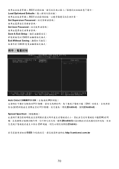
BIOS Load Optimized Defaults BIOS Set Supervisor Password Set User Password Save & Exit Setup CMOS Exit Without Saving CMOS Auto Detect DIMM/PCI ClK PCI PCI EMI PCI Enabled)、關閉(Disabled)。 Spread Spectrum EMI Disabled EMI Enable BIOS http://cweb.msi.com.tw 70
BIOS Load Optimized Defaults BIOS Set Supervisor Password Set User Password Save & Exit Setup CMOS Exit Without Saving CMOS Auto Detect DIMM/PCI ClK PCI PCI EMI PCI Enabled)、關閉(Disabled)。 Spread Spectrum EMI Disabled EMI Enable BIOS http://cweb.msi.com.tw 70
User Guide
Page 91
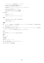
VIA VT8237 MAC + VIA 6103 PHY - 1 RJ45 LAN Jack BIOS BIOS Plug & Play Desktop Management Interface(DMI Micro-ATX 245 mm x 192mm 取付 ! 6 PS2 64MB VRAM CPU 87 - 1 SPP/EPP/ECP 2 SATA KM400 & KM400A のみ) - 8 USB 2.0/1.1 4 4) - 3 Line-In/Line-Out/Mic-In COM2 Intel VIA1617A AC'97 5.1 LAN -
VIA VT8237 MAC + VIA 6103 PHY - 1 RJ45 LAN Jack BIOS BIOS Plug & Play Desktop Management Interface(DMI Micro-ATX 245 mm x 192mm 取付 ! 6 PS2 64MB VRAM CPU 87 - 1 SPP/EPP/ECP 2 SATA KM400 & KM400A のみ) - 8 USB 2.0/1.1 4 4) - 3 Line-In/Line-Out/Mic-In COM2 Intel VIA1617A AC'97 5.1 LAN -
User Guide
Page 101
BIOS の設定 POST(Power On Self Test DEL DEL: Setup F11: Boot Menu F12: Network boot TAB: Logo
BIOS の設定 POST(Power On Self Test DEL DEL: Setup F11: Boot Menu F12: Network boot TAB: Logo
User Guide
Page 102
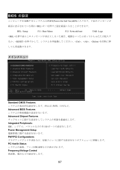
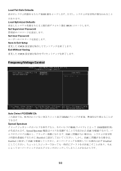
Load Fail-Safe Defaults BIOS Load Optimized Defaults BIOS Set Supervisor Password Set User Password Save & Exit Setup CMOS Exit Without Saving CMOS Frequency/Voltage Control Auto Detect PCI/DIMM Clk PCI DIMM Spread Spectrum EMI Spread Spectrum EMI EMI Disabled EMI Enabled EMI Disabled 98
Load Fail-Safe Defaults BIOS Load Optimized Defaults BIOS Set Supervisor Password Set User Password Save & Exit Setup CMOS Exit Without Saving CMOS Frequency/Voltage Control Auto Detect PCI/DIMM Clk PCI DIMM Spread Spectrum EMI Spread Spectrum EMI EMI Disabled EMI Enabled EMI Disabled 98


