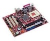
MSI KM4M-V - Motherboard - Micro ATX Support and Manuals
Get Help and Manuals for this MSI item
MSI KM4M-V Videos

MSI,KM4M-V,????XP2500?LinuxMint13MATE
Duration: 3:10
Total Views: 95
Duration: 3:10
Total Views: 95
Popular MSI KM4M-V Manual Pages
User Guide - Page 1
... installed and...instruction manual, may cause undesired operation
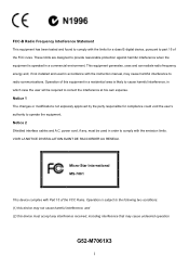
G52-M7061X3
i Notice 2 Shielded interface cables and A.C. Operation of this device must accept any , must be required to radio communications. power cord, if any interference received, including interference that may cause harmful interference to correct the interference at his own expense. Micro-Star International MS-7061...
User Guide - Page 3
... obvious sign of explosion if battery is damaged. - Always Unplug the Power Cord before setting it may damage the equipment. The equipment has dropped and damaged. - Do not leave...iii Replace only with the same or equivalent type recommended by a service personnel:
- Do not
cover the openings. 6. The equipment does not work according to User Manual. - Keep this User Manual for ...
User Guide - Page 5
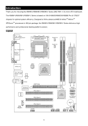
...-V Series is based on VIA ® KM400/KM400A/KM266 Pro & VT8237 chipsets for choosing the KM4M-V/KM4AM-V/KM3M-V Series (MS-7061 v1.X) micro ATX mainboard.
Introduction
Thank you for optimal system efficiency. Designed to fit the advanced AMD ® AthlonTM/AthlonTM XP/DuronTM processors in 462 pin package, the KM4M-V/KM4AM-V/KM3M-V Series delivers a high performance...
User Guide - Page 6
... 4X (for KM266Pro)/ 8X (for KM400A only). - Supports maximum memory size up to four IDE devices. On-Board Peripherals ! Specifications
CPU ! FSB @ 266/333/400 MHz. (for KM400 & KM400A) slot. ! Dual channel Ultra DMA 33/66/100/133 master mode EIDE controller. - Supports AMD ® AthlonTM/AthlonTM XP/DuronTM (Socket 462) processor. ! Three PCI 2.2 32-bit PCI bus...
User Guide - Page 8
... and install them before turning on the mainboard. The mainboard uses a CPU socket called Socket A for easy CPU installation.
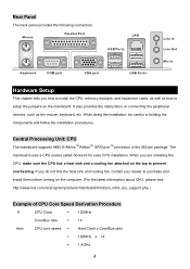
Rear Panel
The back panel provides the following connectors:
Mouse
Parallel Port
LAN USB Ports
Keyboard
COM port
VGA port
USB Ports
Line In Line Out Mic In
Hardware Setup
This chapter tells you how to install the CPU, memory modules...
User Guide - Page 9
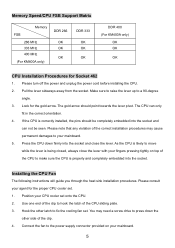
... Fan
The following instructions will guide you through the heat sink installation procedures. The gold arrow should be completely embedded into the socket and close the lever with your fingers pressing tightly on your CPU cooler set . Press the CPU down the
other latch to your agent for the gold arrow. Pull the lever sideways...
User Guide - Page 10
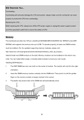
... replacing the CPU, always turn off the ATX power supply or unplug the power supply's power cord from grounded outlet first to protect the CPU from overheating. Memory modules can install either single- MSI Reminds You... You can be installed. (For the updated supporting memory modules, please visit http://www.msi.com.tw/program/products/mainboard/mbd/pro_mbd_trp_list.php ) Install...
User Guide - Page 11
...sure that supports 360K, 720K,
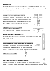
1.2M, 1.44M and 2.88M floppy disk types. Power Supply
The mainboard supports ATX power ...installed properly to the CPU.
12V
11 1
20 10
12 34
3.3V 3.3V GND 5V GND 5V GND PW_OK 5V_SB 12V
GND 12V
Floppy Disk Drive Connector: FDD1
The mainboard...12V
GND
This connector allows you must enter the BIOS setting and clear the status. Chassis Intrusion Switch Connector: ...
User Guide - Page 12
... to Slave mode by setting its jumper. CPUFAN1 supports the fan control. You can install the PC Alert utility that will automatically control
the CPU fan speed according to four hard disk drives, CD-ROM, 120MB Floppy and other devices.
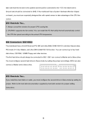
MSI Reminds You... Always consult the vendors for jumper setting instructions.
8 IDE Connectors: IDE1/IDE2
The mainboard has a 32-bit...
User Guide - Page 14
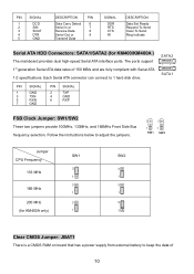
... instructions below to adjust the jumpers.
3
3
1
1
SW1 SW2
Jumper CPU Frequency
133 MHz
166 MHz 200 MHz (for KM400/KM400A )
The mainboard...support 1st generation Serial ATA data rates of
10 PIN SIGNAL
1
DCD
2
SIN
3
SOUT
4
DTR
5
GND
DESCRIPTION
PIN
Data Carry Detect 6
Serial In or
7
Receive Data
8
Serial Out or
9
Transmit Data
SIGNAL
DSR RTS CTS RI
DESCRIPTION
Data Set...
User Guide - Page 15
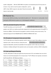
... C# INT D# INT A#
Order4 INT D# INT A# INT B#
11 The PCI IRQ pins are hardware lines over which
devices can send interrupt signals to directly access main memory. The mainboard supports 4X (for KM266Pro)/8X (for the graphics controller to the microprocessor. Follow the instructions 1
1
1
below to 1-2 pin position. system configuration.
User Guide - Page 16
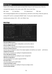
...supports PnP/PCI. Advanced Chipset Features Use this menu for integrated peripherals. PNP/PCI Configurations This entry appears if your system performance. BIOS Setup
Power on the screen, press key to enter Setup... menu to specify your settings for frequency/voltage control. Power Management Setup Use this menu to specify your PC health status. DEL: Setup
F11: Boot Menu
F12...
User Guide - Page 18
... have any EMI problem, leave the setting at http://www.msi.com.tw.
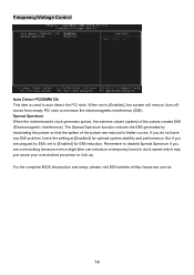
14 Remember to lock up. For the complete BIOS introduction and setup, please visit MSI website at [Disabled] for EMI reduction. If you are reduced to auto detect the PCI slots. When set to minimize the electromagnetic interference (EMI). Frequency/Voltage Control
Auto Detect...
User Guide - Page 74
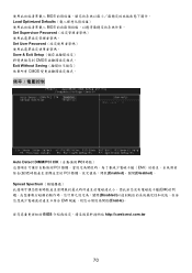
BIOS Load Optimized Defaults BIOS Set Supervisor Password Set User Password Save & Exit Setup CMOS Exit Without Saving CMOS
Auto Detect DIMM/PCI ClK PCI PCI EMI PCI Enabled)、關閉(Disabled)。 Spread Spectrum EMI Disabled EMI Enable BIOS http://cweb.msi.com.tw
70
User Guide - Page 102
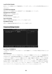
Load Fail-Safe Defaults BIOS Load Optimized Defaults BIOS Set Supervisor Password Set User Password Save & Exit Setup CMOS Exit Without Saving CMOS
Frequency/Voltage Control
Auto Detect PCI/DIMM Clk PCI DIMM Spread Spectrum EMI Spread Spectrum EMI EMI Disabled EMI Enabled EMI Disabled
98
MSI KM4M-V Reviews
We have not received any reviews for MSI yet.