User Guide
Page 2
... Kensington Technology Group. Windows® 98/2000/NT/XP are registered trademarks of NVIDIA Corporation in the United States and/or other countries. Kensington and MicroSaver are the properties of Multi-language version for PCB 1.x April 2004 with chipsets VIA® KM400/KM400A/KM266 Pro & VT8237 V1.1 FSB Clock jumpers (SW1&SW2) & SATA1/2 update May 2004 V1.2 Update FSB frequency...
... Kensington Technology Group. Windows® 98/2000/NT/XP are registered trademarks of NVIDIA Corporation in the United States and/or other countries. Kensington and MicroSaver are the properties of Multi-language version for PCB 1.x April 2004 with chipsets VIA® KM400/KM400A/KM266 Pro & VT8237 V1.1 FSB Clock jumpers (SW1&SW2) & SATA1/2 update May 2004 V1.2 Update FSB frequency...
User Guide
Page 3
... should be noted. 10. Do not leave this User Manual for air convection hence protects the equipment from humidity. 4. Safety Instructions 1. Keep this equipment in an environment unconditioned, storage temperature above 60° C (140°F), it work according to User Manual. - The power cord or plug is incorrectly replaced. Always read the safety instructions carefully. 2. Do not cover the openings. 6. Do not...
... should be noted. 10. Do not leave this User Manual for air convection hence protects the equipment from humidity. 4. Safety Instructions 1. Keep this equipment in an environment unconditioned, storage temperature above 60° C (140°F), it work according to User Manual. - The power cord or plug is incorrectly replaced. Always read the safety instructions carefully. 2. Do not cover the openings. 6. Do not...
User Guide
Page 5
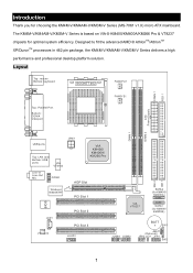
Layout Top : mouse Bottom: keyboard SOCKET 462 FANCPU1 CONN 1 FDD 1 Top : Parallel Port Bottom: COM A VGA port FANSYS1 ATX Power Supply DIMM 2 DIMM 1 USB ports JPW1 Top: LAN Jack Bottom: USB ports VIA VT6103 Line-In Line-Out Mic COM2 Winbond W83697HF AGP Slot PCI Slot 1 BIOS JCD1 VIA VT1617A PCI Slot 2 PCI Slot 3 JAUD1 VIA VT8237 SATA2 (for KM400/ KM400A) SATA1 (for choosing the KM4M-V/KM4AM-V/KM3M-V Series (MS-7061 v1.X) micro ATX mainboard. Introduction Thank you...
Layout Top : mouse Bottom: keyboard SOCKET 462 FANCPU1 CONN 1 FDD 1 Top : Parallel Port Bottom: COM A VGA port FANSYS1 ATX Power Supply DIMM 2 DIMM 1 USB ports JPW1 Top: LAN Jack Bottom: USB ports VIA VT6103 Line-In Line-Out Mic COM2 Winbond W83697HF AGP Slot PCI Slot 1 BIOS JCD1 VIA VT1617A PCI Slot 2 PCI Slot 3 JAUD1 VIA VT8237 SATA2 (for KM400/ KM400A) SATA1 (for choosing the KM4M-V/KM4AM-V/KM3M-V Series (MS-7061 v1.X) micro ATX mainboard. Introduction Thank you...
User Guide
Page 6
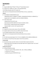
...). - ACPI & PC2001 compliant enhanced power management. - On-Board Peripherals includes: - 1 floppy port supports 2 FDDs with PIO, Bus Master and Ultra DMA 33/66/100/133 operation modes. Dual channel Ultra DMA 33/66/100/133 master mode EIDE controller. - Supports four memory banks using two 184-pin DDR DIMMS. ! Dual channel master mode IDE controller on the VIA ® VT8237 Chipset provides IDE HDD/CD-ROM with 360K, 720K, 1.2M, 1.44M and 2.88Mbytes. - 1 serial port and 1 VGA port. - 1 parallel port supports...
...). - ACPI & PC2001 compliant enhanced power management. - On-Board Peripherals includes: - 1 floppy port supports 2 FDDs with PIO, Bus Master and Ultra DMA 33/66/100/133 operation modes. Dual channel Ultra DMA 33/66/100/133 master mode EIDE controller. - Supports four memory banks using two 184-pin DDR DIMMS. ! Dual channel master mode IDE controller on the VIA ® VT8237 Chipset provides IDE HDD/CD-ROM with 360K, 720K, 1.2M, 1.44M and 2.88Mbytes. - 1 serial port and 1 VGA port. - 1 parallel port supports...
User Guide
Page 7
... - 1 RJ45 LAN Jack. Dimension ! Supports PS2 Keyboard/Mouse. ! Audio - Micro-ATX Form Factor: 245 mm x 192mm. COM2 on board with pin header (Intel pin-define). Mounting ! 6 mounting holes. - 2 SATA connectors (for KM400/KM400A only) - 8 USB 2.0 ports (Rear * 4/ Front * 4). - 3 audio (Line-In/Line-Out/Mic) ports. - VIA1617A codec. - 5.1 channel AC'97 software Audio. The mainboard BIOS provides "Plug & Play" BIOS which detects the peripheral devices and expansion cards of the board automatically. ! Hardware monitor is up to monitor CPU's temperature/voltage. 3 BIOS !
... - 1 RJ45 LAN Jack. Dimension ! Supports PS2 Keyboard/Mouse. ! Audio - Micro-ATX Form Factor: 245 mm x 192mm. COM2 on board with pin header (Intel pin-define). Mounting ! 6 mounting holes. - 2 SATA connectors (for KM400/KM400A only) - 8 USB 2.0 ports (Rear * 4/ Front * 4). - 3 audio (Line-In/Line-Out/Mic) ports. - VIA1617A codec. - 5.1 channel AC'97 software Audio. The mainboard BIOS provides "Plug & Play" BIOS which detects the peripheral devices and expansion cards of the board automatically. ! Hardware monitor is up to monitor CPU's temperature/voltage. 3 BIOS !
User Guide
Page 8
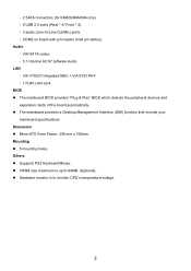
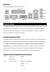
... then CPU core speed = Host Clock x Core/Bus ratio = 100MHz x 14 = 1.4GHz 4 If you do not find the heat sink and cooling fan, contact your dealer to purchase and install them before turning on the mainboard. Rear Panel The back panel provides the following connectors: Mouse Parallel Port LAN USB Ports Keyboard COM port VGA port USB Ports Line In Line Out Mic In Hardware Setup This chapter tells you how to install the CPU, memory modules...
... then CPU core speed = Host Clock x Core/Bus ratio = 100MHz x 14 = 1.4GHz 4 If you do not find the heat sink and cooling fan, contact your dealer to purchase and install them before turning on the mainboard. Rear Panel The back panel provides the following connectors: Mouse Parallel Port LAN USB Ports Keyboard COM port VGA port USB Ports Line In Line Out Mic In Hardware Setup This chapter tells you how to install the CPU, memory modules...
User Guide
Page 9
... the correct installation procedures may need a screw drive to the power supply connector provided on top of the CPU sliding plate. 3. Connect the fan to press down firmly into the socket and can only fit in the correct orientation. 4. Pull the lever sideways away from the socket. Position your mainboard. 5. Press the CPU down the other latch to your CPU cooler set . Make sure...
... the correct installation procedures may need a screw drive to the power supply connector provided on top of the CPU sliding plate. 3. Connect the fan to press down firmly into the socket and can only fit in the correct orientation. 4. Pull the lever sideways away from the socket. Position your mainboard. 5. Press the CPU down the other latch to your CPU cooler set . Make sure...
User Guide
Page 10
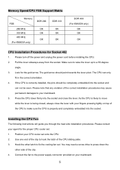
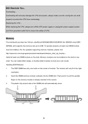
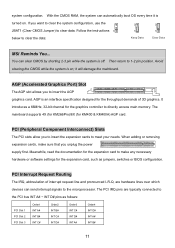
... the golden finger on the slots. MSI Reminds You... While replacing the CPU, always turn off the ATX power supply or unplug the power supply's power cord from overheating. or double-sided modules to ensure the safety of CPU. Memory The mainboard provides two 184-pin unbuffered DDR266/DDR333/DDR400 (for KM400A only) DDR SDRAM, and supports the memory size up to protect the CPU from grounded outlet first...
... the golden finger on the slots. MSI Reminds You... While replacing the CPU, always turn off the ATX power supply or unplug the power supply's power cord from overheating. or double-sided modules to ensure the safety of CPU. Memory The mainboard provides two 184-pin unbuffered DDR266/DDR333/DDR400 (for KM400A only) DDR SDRAM, and supports the memory size up to protect the CPU from grounded outlet first...
User Guide
Page 11
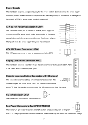
... Floppy Disk Drive Connector: FDD1 The mainboard provides a standard floppy disk drive connector that no damage will be short. Before inserting the power supply connector, always make sure the plug of the power GND GND supply is used to provide power to ensure that supports 360K, 720K, 1.2M, 1.44M and 2.88M floppy disk types. Chassis Intrusion Switch Connector: JCI1 (Optional) This connector is open, the switch will record this status. When connecting the wire to 2-pin connector chassis switch. If the GND 2 CINTRU 1 Chassis is connected...
... Floppy Disk Drive Connector: FDD1 The mainboard provides a standard floppy disk drive connector that no damage will be short. Before inserting the power supply connector, always make sure the plug of the power GND GND supply is used to provide power to ensure that supports 360K, 720K, 1.2M, 1.44M and 2.88M floppy disk types. Chassis Intrusion Switch Connector: JCI1 (Optional) This connector is open, the switch will record this status. When connecting the wire to 2-pin connector chassis switch. If the GND 2 CINTRU 1 Chassis is connected...
User Guide
Page 12
... connect a Master and a Slave drive. IDE2 can install the PC Alert utility that will automatically control the CPU fan speed according to take note that provides PIO mode 0~4, Bus Master, and Ultra DMA 33/66/100/133 function. If you install two hard disks on -board, you must configure second hard drive to the hard disk documentation supplied by setting the jumper accordingly. take advantage of the CPU fan control. IDE Connectors: IDE1/IDE2 The mainboard has a 32-bit...
... connect a Master and a Slave drive. IDE2 can install the PC Alert utility that will automatically control the CPU fan speed according to take note that provides PIO mode 0~4, Bus Master, and Ultra DMA 33/66/100/133 function. If you install two hard disks on -board, you must configure second hard drive to the hard disk documentation supplied by setting the jumper accordingly. take advantage of the CPU fan control. IDE Connectors: IDE1/IDE2 The mainboard has a 32-bit...
User Guide
Page 13
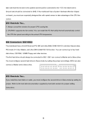
... 1 9 HDD Reset LED Switch JFP1 Speaker 2 8 1 7 Power LED JFP2 Front Panel Audio Connector: JAUD1 The front panel audio connector allows you do not want to connect to the front audio header, pins 5 & 6, 9 & 10 have to be jumpered in order to have signal output directed to the front panel switches and LEDs. You can attach a serial mouse or other serial 9 10 device directly to a maximum throughput of 480Mbps, which is 40 times faster than USB 1.1, and...
... 1 9 HDD Reset LED Switch JFP1 Speaker 2 8 1 7 Power LED JFP2 Front Panel Audio Connector: JAUD1 The front panel audio connector allows you do not want to connect to the front audio header, pins 5 & 6, 9 & 10 have to be jumpered in order to have signal output directed to the front panel switches and LEDs. You can attach a serial mouse or other serial 9 10 device directly to a maximum throughput of 480Mbps, which is 40 times faster than USB 1.1, and...
User Guide
Page 14
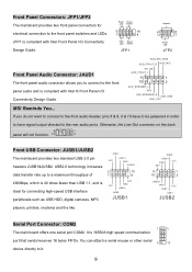
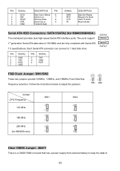
Each Serial ATA connector can connect to 1 hard disk drive. Follow the instructions below to adjust the jumpers. 3 3 1 1 SW1 SW2 Jumper CPU Frequency 133 MHz 166 MHz 200 MHz (for KM400/KM400A ) The mainboard provides dual high-speed Serial ATA interface ports. The ports support 1st generation Serial ATA data rates of 10 SATA2 7 1 SATA1 PIN SIGNAL 1 GND 3 TXN 5 RXN 7 GND PIN SIGNAL 2 TXP 4 GND 6 RXP FSB Clock Jumper: SW1/SW2 These two jumpers provide 100MHz...
Each Serial ATA connector can connect to 1 hard disk drive. Follow the instructions below to adjust the jumpers. 3 3 1 1 SW1 SW2 Jumper CPU Frequency 133 MHz 166 MHz 200 MHz (for KM400/KM400A ) The mainboard provides dual high-speed Serial ATA interface ports. The ports support 1st generation Serial ATA data rates of 10 SATA2 7 1 SATA1 PIN SIGNAL 1 GND 3 TXN 5 RXN 7 GND PIN SIGNAL 2 TXP 4 GND 6 RXP FSB Clock Jumper: SW1/SW2 These two jumpers provide 100MHz...
User Guide
Page 15
... Clear Data MSI Reminds You... AGP (Accelerated Graphics Port) Slot The AGP slot allows you to insert the expansion cards to directly access main memory. it is off. Avoid clearing the CMOS while the system is an interface specification designed for the graphics controller to meet your needs. The PCI IRQ pins are hardware lines over which devices can send interrupt signals to the PCI bus INT A# ~ INT D# pins as jumpers, switches or BIOS configuration...
... Clear Data MSI Reminds You... AGP (Accelerated Graphics Port) Slot The AGP slot allows you to insert the expansion cards to directly access main memory. it is off. Avoid clearing the CMOS while the system is an interface specification designed for the graphics controller to meet your needs. The PCI IRQ pins are hardware lines over which devices can send interrupt signals to the PCI bus INT A# ~ INT D# pins as jumpers, switches or BIOS configuration...
User Guide
Page 16
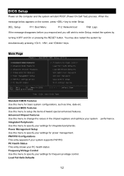
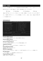
... , , and keys. Load Fail-Safe Defaults 12 PC Health Status This entry shows your settings for frequency/voltage control. Integrated Peripherals Use this menu to specify your system performance. Frequency/Voltage Control Use this menu to specify your PC health status. BIOS Setup Power on the screen, press key to enter Setup. You may also restart the system by turning it OFF and On or pressing the RESET button. Advanced Chipset Features Use this menu to change the...
... , , and keys. Load Fail-Safe Defaults 12 PC Health Status This entry shows your settings for frequency/voltage control. Integrated Peripherals Use this menu to specify your system performance. Frequency/Voltage Control Use this menu to specify your PC health status. BIOS Setup Power on the screen, press key to enter Setup. You may also restart the system by turning it OFF and On or pressing the RESET button. Advanced Chipset Features Use this menu to change the...
User Guide
Page 18
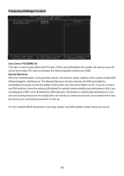
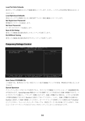
...). For the complete BIOS introduction and setup, please visit MSI website at [Disabled] for EMI reduction. Remember to minimize the electromagnetic interference (EMI). Spread Spectrum When the motherboard's clock generator pulses, the extreme values (spikes) of the pulses are overclocking because even a slight jitter can introduce a temporary boost in clock speed which may just cause your overclocked processor to auto detect the PCI slots.
...). For the complete BIOS introduction and setup, please visit MSI website at [Disabled] for EMI reduction. Remember to minimize the electromagnetic interference (EMI). Spread Spectrum When the motherboard's clock generator pulses, the extreme values (spikes) of the pulses are overclocking because even a slight jitter can introduce a temporary boost in clock speed which may just cause your overclocked processor to auto detect the PCI slots.

User Guide
Page 60
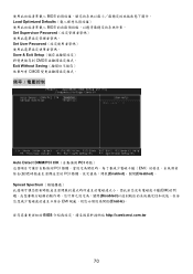
BIOS 设置 POST DEL DEL: Setup F11: Boot Menu F12: Network boot TAB: Logo Setup Reset 键, Ctrl> 和
BIOS 设置 POST DEL DEL: Setup F11: Boot Menu F12: Network boot TAB: Logo Setup Reset 键, Ctrl> 和
User Guide
Page 74
BIOS Load Optimized Defaults BIOS Set Supervisor Password Set User Password Save & Exit Setup CMOS Exit Without Saving CMOS Auto Detect DIMM/PCI ClK PCI PCI EMI PCI Enabled)、關閉(Disabled)。 Spread Spectrum EMI Disabled EMI Enable BIOS http://cweb.msi.com.tw 70
BIOS Load Optimized Defaults BIOS Set Supervisor Password Set User Password Save & Exit Setup CMOS Exit Without Saving CMOS Auto Detect DIMM/PCI ClK PCI PCI EMI PCI Enabled)、關閉(Disabled)。 Spread Spectrum EMI Disabled EMI Enable BIOS http://cweb.msi.com.tw 70
User Guide
Page 91
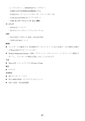
VIA VT8237 MAC + VIA 6103 PHY - 1 RJ45 LAN Jack BIOS BIOS Plug & Play Desktop Management Interface(DMI Micro-ATX 245 mm x 192mm 取付 ! 6 PS2 64MB VRAM CPU 87 - 1 SPP/EPP/ECP 2 SATA KM400 & KM400A のみ) - 8 USB 2.0/1.1 4 4) - 3 Line-In/Line-Out/Mic-In COM2 Intel VIA1617A AC'97 5.1 LAN -
VIA VT8237 MAC + VIA 6103 PHY - 1 RJ45 LAN Jack BIOS BIOS Plug & Play Desktop Management Interface(DMI Micro-ATX 245 mm x 192mm 取付 ! 6 PS2 64MB VRAM CPU 87 - 1 SPP/EPP/ECP 2 SATA KM400 & KM400A のみ) - 8 USB 2.0/1.1 4 4) - 3 Line-In/Line-Out/Mic-In COM2 Intel VIA1617A AC'97 5.1 LAN -
User Guide
Page 101
BIOS の設定 POST(Power On Self Test DEL DEL: Setup F11: Boot Menu F12: Network boot TAB: Logo
BIOS の設定 POST(Power On Self Test DEL DEL: Setup F11: Boot Menu F12: Network boot TAB: Logo
User Guide
Page 102
Load Fail-Safe Defaults BIOS Load Optimized Defaults BIOS Set Supervisor Password Set User Password Save & Exit Setup CMOS Exit Without Saving CMOS Frequency/Voltage Control Auto Detect PCI/DIMM Clk PCI DIMM Spread Spectrum EMI Spread Spectrum EMI EMI Disabled EMI Enabled EMI Disabled 98
Load Fail-Safe Defaults BIOS Load Optimized Defaults BIOS Set Supervisor Password Set User Password Save & Exit Setup CMOS Exit Without Saving CMOS Frequency/Voltage Control Auto Detect PCI/DIMM Clk PCI DIMM Spread Spectrum EMI Spread Spectrum EMI EMI Disabled EMI Enabled EMI Disabled 98


