

User Guide
Page 4
... Part 15 of the FCC Rules. power cord, if any interference received, including interference that interference will not occur in a residential installation. Micro-Star International MS-7551 This device complies with the limits for help. Notice 2 Shielded interface cables and A.C. Operation is eq uip men t h as been tested and found to comply...
... Part 15 of the FCC Rules. power cord, if any interference received, including interference that interference will not occur in a residential installation. Micro-Star International MS-7551 This device complies with the limits for help. Notice 2 Shielded interface cables and A.C. Operation is eq uip men t h as been tested and found to comply...

User Guide
Page 10
The KA790GX/ KA780G/ KA780V Series mainboards are based on AM D® RS780D/ RS780/ RS780C & SB700/ SB750 chipsets for optimal system efficiency. Designed to fit the advanced AM D® Phenom FX/X4/X3/X2, Athlon 64 FX/ X2 and Sempron processors in socket AM2+, the KA790GX/ KA780G/ KA780V Series deliver a high performance and professional desktop platform solution. 1-1 Getting Started Chapter 1 Getting Started T hank you f or choosing the KA790GX/ KA780G/ KA780V Series (MS-7551 v1.X) ATX mainboards.
The KA790GX/ KA780G/ KA780V Series mainboards are based on AM D® RS780D/ RS780/ RS780C & SB700/ SB750 chipsets for optimal system efficiency. Designed to fit the advanced AM D® Phenom FX/X4/X3/X2, Athlon 64 FX/ X2 and Sempron processors in socket AM2+, the KA790GX/ KA780G/ KA780V Series deliver a high performance and professional desktop platform solution. 1-1 Getting Started Chapter 1 Getting Started T hank you f or choosing the KA790GX/ KA780G/ KA780V Series (MS-7551 v1.X) ATX mainboards.
User Guide
Page 11
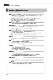
c om. t w / i ndex . North Bridge: AMD® RS780D/ RS780/ RS780C chipset - ms i. Supports 10/100/1000 Fast Ethernet by Realtek® ALC888 - Chip integrated by Realtek 8111C Audio - Supports 4 pin CPU Fan Pin-Header with jack sensing - t w / i ... with Fan Speed Control (For the latest information about CPU, please visit ht t p: / / g loba l. Supports 1 FDD with Azalia 1.0 spec IDE - 1 IDE port by SB700/SB750 - ms i . Supports Ultra DMA 66/100/133 mode - SATA1~5 support RAID 0/ 1/ 0+1/ 5 mode 1-2 AMD® Phenom FX/X4/X3/X2, Athlon 64 FX/X2, Sempron in the...
c om. t w / i ndex . North Bridge: AMD® RS780D/ RS780/ RS780C chipset - ms i. Supports 10/100/1000 Fast Ethernet by Realtek® ALC888 - Chip integrated by Realtek 8111C Audio - Supports 4 pin CPU Fan Pin-Header with jack sensing - t w / i ... with Fan Speed Control (For the latest information about CPU, please visit ht t p: / / g loba l. Supports 1 FDD with Azalia 1.0 spec IDE - 1 IDE port by SB700/SB750 - ms i . Supports Ultra DMA 66/100/133 mode - SATA1~5 support RAID 0/ 1/ 0+1/ 5 mode 1-2 AMD® Phenom FX/X4/X3/X2, Athlon 64 FX/X2, Sempron in the...

User Guide
Page 13
... SB700 / SB750 POWER1 (Optional) RESET1 (Optional) C L R _ CM OS1 (Optional) BATT + JBAT1 JFP2 FDD 1 JCOM1 JUSB1 JUSB2 JUSB3 JFP1 KA790GX/ KA780G/ KA780V Series (MS-7551 v1.X) ATX Mainboard 1-4 IDE 1 S ATA2 SATA1 S ATA4 SATA3 SATA5 JTPM1 MS-7551 Mainboard Mainboard Layout DIMM1 DIMM2 DIMM3 DIMM4 JPWR2 Top : mouse or keyboard Bottom:USB ports Top: VGA port Bottom...
... SB700 / SB750 POWER1 (Optional) RESET1 (Optional) C L R _ CM OS1 (Optional) BATT + JBAT1 JFP2 FDD 1 JCOM1 JUSB1 JUSB2 JUSB3 JFP1 KA790GX/ KA780G/ KA780V Series (MS-7551 v1.X) ATX Mainboard 1-4 IDE 1 S ATA2 SATA1 S ATA4 SATA3 SATA5 JTPM1 MS-7551 Mainboard Mainboard Layout DIMM1 DIMM2 DIMM3 DIMM4 JPWR2 Top : mouse or keyboard Bottom:USB ports Top: VGA port Bottom...

User Guide
Page 18
... O Incorrect CPU placement 5. Please note that any violation of the CPU to a 90-degree angle. The CPU can not be completely embedded into the socket. MS-7551 Mainboard CPU Installation Procedures for the gold arrow on top of the correct installation procedures may cause permanent damages to move while the lever is...
... O Incorrect CPU placement 5. Please note that any violation of the CPU to a 90-degree angle. The CPU can not be completely embedded into the socket. MS-7551 Mainboard CPU Installation Procedures for the gold arrow on top of the correct installation procedures may cause permanent damages to move while the lever is...

User Guide
Page 20
.... Enabling Dual-Channel mode can transmit and receive data with two data bus lines simultaneously. For more information on compatible components, please visit http://global.msi.com. MS-7551 Mainboard Memory These DIMM slots are used for population rules under Dual-Channel mode. 1 DIMM1 DIMM2 DIMM3 DIMM4 2 DIMM1 DIMM2 DIMM3 DIMM4 Installed Empty...
.... Enabling Dual-Channel mode can transmit and receive data with two data bus lines simultaneously. For more information on compatible components, please visit http://global.msi.com. MS-7551 Mainboard Memory These DIMM slots are used for population rules under Dual-Channel mode. 1 DIMM1 DIMM2 DIMM3 DIMM4 2 DIMM1 DIMM2 DIMM3 DIMM4 Installed Empty...

User Guide
Page 22
... power connector is inserted in the proper orientation and the pins are connected to proper ATX power supplies to the image at the right hand). MS-7551 Mainboard Power Supply ATX 24-Pin Power Connector: JPWR2 This connector allows you like to use the 20-pin ATX power supply as you to...
... power connector is inserted in the proper orientation and the pins are connected to proper ATX power supplies to the image at the right hand). MS-7551 Mainboard Power Supply ATX 24-Pin Power Connector: JPWR2 This connector allows you like to use the 20-pin ATX power supply as you to...

User Guide
Page 24
... is selected. On 1000 Mbit/sec data rate is communicating with another computer on the LAN. Audio Ports These audio connectors are used for microphones. MS-7551 Mainboard LAN The standard RJ-45 LAN jack is for connection to it. On 100 Mbit/sec data rate is a connector for speakers or headphones...
... is selected. On 1000 Mbit/sec data rate is communicating with another computer on the LAN. Audio Ports These audio connectors are used for microphones. MS-7551 Mainboard LAN The standard RJ-45 LAN jack is for connection to it. On 100 Mbit/sec data rate is a connector for speakers or headphones...
User Guide
Page 26
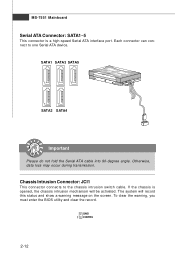
GND 1 CINTRU 2-12 Each connector can connect to the chassis intrusion switch cable. If the chassis is a high-speed Serial ATA interface port. MS-7551 Mainboard Serial ATA Connector: SATA1~5 This connector is opened, the chassis intrusion mechanism will record this status and show a warning message on the screen. Otherwise, ...
GND 1 CINTRU 2-12 Each connector can connect to the chassis intrusion switch cable. If the chassis is a high-speed Serial ATA interface port. MS-7551 Mainboard Serial ATA Connector: SATA1~5 This connector is opened, the chassis intrusion mechanism will record this status and show a warning message on the screen. Otherwise, ...

User Guide
Page 28
Please refer to connect the front panel audio and is compliant with Intel® Front Panel I/O Connectivity Design Guide. MS-7551 Mainboard Front Panel Audio Connector: JAUD1 This connector allows you to the TPM security platform manual for future use to control headphone amplifier 8 KEY No ...
Please refer to connect the front panel audio and is compliant with Intel® Front Panel I/O Connectivity Design Guide. MS-7551 Mainboard Front Panel Audio Connector: JAUD1 This connector allows you to the TPM security platform manual for future use to control headphone amplifier 8 KEY No ...

User Guide
Page 30
... + 78 JFP2 Pin Definition PIN SIGNAL 1 GND 2 SPK- 3 SLED 4 BUZ+ 5 PLED 6 BUZ- 7 NC 8 SPK+ DESCRIPTION Ground SpeakerSuspend LED Buzzer+ Power LED BuzzerNo connection Speaker+ 2-16 MS-7551 Mainboard Front Panel Connectors: JFP1, JFP2 These connectors are for electrical connection to GND Reserved. Power Power LED Switch +- Power JFP2 LED +-
... + 78 JFP2 Pin Definition PIN SIGNAL 1 GND 2 SPK- 3 SLED 4 BUZ+ 5 PLED 6 BUZ- 7 NC 8 SPK+ DESCRIPTION Ground SpeakerSuspend LED Buzzer+ Power LED BuzzerNo connection Speaker+ 2-16 MS-7551 Mainboard Front Panel Connectors: JFP1, JFP2 These connectors are for electrical connection to GND Reserved. Power Power LED Switch +- Power JFP2 LED +-

User Guide
Page 32
Avoid clearing the CMOS while the system is off. MS-7551 Mainboard Jumpers Clear CMOS Jumper: JBAT1 There is a CMOS RAM onboard that has a power supply from an external battery to clear data. If you want to clear the system configuration, set the jumper to keep the data of system configuration. Then return to 1-2 pin position. it is turned on ; W ith the CMOS RAM, the system can clear CMOS by shorting 2-3 pin while the system is on . JBAT1 1 3 1 Keep Data 3 1 Clear Data Important You can automatically boot OS every time it will damage the mainboard. 2-18
Avoid clearing the CMOS while the system is off. MS-7551 Mainboard Jumpers Clear CMOS Jumper: JBAT1 There is a CMOS RAM onboard that has a power supply from an external battery to clear data. If you want to clear the system configuration, set the jumper to keep the data of system configuration. Then return to 1-2 pin position. it is turned on ; W ith the CMOS RAM, the system can clear CMOS by shorting 2-3 pin while the system is on . JBAT1 1 3 1 Keep Data 3 1 Clear Data Important You can automatically boot OS every time it will damage the mainboard. 2-18

User Guide
Page 34
MS-7551 Mainboard Switch This mainboard provides the following warning message will explain how to set the computer's function. This section will display during boot, the following ...
MS-7551 Mainboard Switch This mainboard provides the following warning message will explain how to set the computer's function. This section will display during boot, the following ...

User Guide
Page 36
From the Graphics Adapter list, select the graphics card that acts as are all cards in the CatalystTM Control Center, click CrossFireTM. 3. Select Enable CrossFireTM. 5. MS-7551 Mainboard 1. Click Apply. From the Graphics Settings tree in the configuration as the Display GPU. 4. W hen Hybrid CrossfireXTM is enabled, GPU Accelerated Physics is automatically disabled for all displays except the one used by Hybrid CrossfireXTM. Select the Advanced View from the view drop menu. 2. More details please refer to AMD officially website. 2-22
From the Graphics Adapter list, select the graphics card that acts as are all cards in the CatalystTM Control Center, click CrossFireTM. 3. Select Enable CrossFireTM. 5. MS-7551 Mainboard 1. Click Apply. From the Graphics Settings tree in the configuration as the Display GPU. 4. W hen Hybrid CrossfireXTM is enabled, GPU Accelerated Physics is automatically disabled for all displays except the one used by Hybrid CrossfireXTM. Select the Advanced View from the view drop menu. 2. More details please refer to AMD officially website. 2-22
User Guide
Page 39
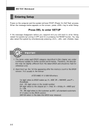
MS-7551 Mainboard Entering Setup Power on the screen, press key to enter Setup, restart the system by simultaneously pressing , , and keys. Important 1. V1.0 refers to the ... digit refers to BIOS maker as A = AMI, W = AWARD, and P = PHOENIX. 2nd - 5th digit refers to the model number. 6th digit refers to the chipset as MS = all standard customers. You may be slightly different from the latest BIOS and should be held for better system performance. Therefore, the description may also...
MS-7551 Mainboard Entering Setup Power on the screen, press key to enter Setup, restart the system by simultaneously pressing , , and keys. Important 1. V1.0 refers to the ... digit refers to BIOS maker as A = AMI, W = AWARD, and P = PHOENIX. 2nd - 5th digit refers to the model number. 6th digit refers to the chipset as MS = all standard customers. You may be slightly different from the latest BIOS and should be held for better system performance. Therefore, the description may also...
User Guide
Page 41
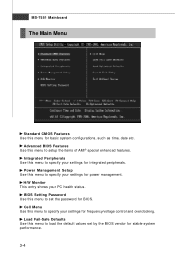
MS-7551 Mainboard The Main Menu Standard CMOS Features Use this menu to setup the items of AMI® special enhanced features. H/W Monitor This entry shows your ...
MS-7551 Mainboard The Main Menu Standard CMOS Features Use this menu to setup the items of AMI® special enhanced features. H/W Monitor This entry shows your ...
User Guide
Page 43
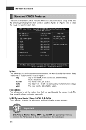
... IDE Primary Master/ Slave, SATA1~5, E-SATA are appearing when you connect the HD devices to select the value you to Dec. The time format is . MS-7551 Mainboard Standard CMOS Features The items in each item. year The year can be adjusted by numeric function keys. Read-only. Date This allows you...
... IDE Primary Master/ Slave, SATA1~5, E-SATA are appearing when you connect the HD devices to select the value you to Dec. The time format is . MS-7551 Mainboard Standard CMOS Features The items in each item. year The year can be adjusted by numeric function keys. Read-only. Date This allows you...
User Guide
Page 45
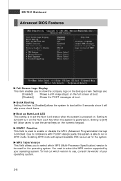
... logo on the full screen at boot. [Disabled] Shows the POST messages at boot. IOAPIC Function This field is able to run in APIC mode. MS-7551 Mainboard Advanced BIOS Features Full Screen Logo Display This item enables you to select which version to use the arrow keys on . Settings are: [Enabled...
... logo on the full screen at boot. [Disabled] Shows the POST messages at boot. IOAPIC Function This field is able to run in APIC mode. MS-7551 Mainboard Advanced BIOS Features Full Screen Logo Display This item enables you to select which version to use the arrow keys on . Settings are: [Enabled...
User Guide
Page 47
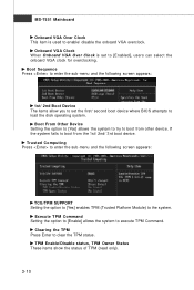
MS-7551 Mainboard Onboard VGA Over Clock This item is set the first/ second boot device where BIOS attempts to load the disk operating system. If the ...
MS-7551 Mainboard Onboard VGA Over Clock This item is set the first/ second boot device where BIOS attempts to load the disk operating system. If the ...
User Guide
Page 49
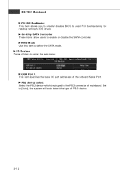
PS2 device select Select the PS/2 device which be pluged to enter the sub-menu: COM Port 1 This item specifies the base I/O port addresses of mainbaord. I/O Devices Press to the PS/2 connector of the onboard Serial Port. Set to define the SATA mode. RAID Mode Use this item to [Auto], the system will auto detect the type of PS/2 device. 3-12 On-Chip SATA Controller These items allow users to IDE drives. MS-7551 Mainboard PCI IDE BusMaster This item allows you to enable/ disable BIOS to used PCI busmastering for reading/ writing to enable or disable the SATA controller.
PS2 device select Select the PS/2 device which be pluged to enter the sub-menu: COM Port 1 This item specifies the base I/O port addresses of mainbaord. I/O Devices Press to the PS/2 connector of the onboard Serial Port. Set to define the SATA mode. RAID Mode Use this item to [Auto], the system will auto detect the type of PS/2 device. 3-12 On-Chip SATA Controller These items allow users to IDE drives. MS-7551 Mainboard PCI IDE BusMaster This item allows you to enable/ disable BIOS to used PCI busmastering for reading/ writing to enable or disable the SATA controller.


