

User Guide
Page 13
... Design Guide. or four-pin head connector. Always consult the vendors for electrical connection to the front panel switches and LEDs. Reset HDD Switch LED 9 1 10 2 Front Panel Audio Connector: JAUD1 The front panel audio connector allows you to AUD_RET_R connect to...is compliant with Intel Front Panel I/O Connectivity Design Guide. CPUFAN can support three- MSI Reminds You... Otherwise, the Line-Out connector on -board, you must configure the setting through the BIOS setup to use a specially designed fan with Intel® Front Panel I/O Connectivity ...
... Design Guide. or four-pin head connector. Always consult the vendors for electrical connection to the front panel switches and LEDs. Reset HDD Switch LED 9 1 10 2 Front Panel Audio Connector: JAUD1 The front panel audio connector allows you to AUD_RET_R connect to...is compliant with Intel Front Panel I/O Connectivity Design Guide. CPUFAN can support three- MSI Reminds You... Otherwise, the Line-Out connector on -board, you must configure the setting through the BIOS setup to use a specially designed fan with Intel® Front Panel I/O Connectivity ...
User Guide
Page 16
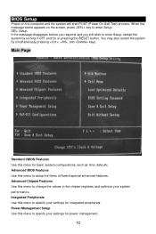
... BIOS Features Use this menu to specify your settings for integrated peripherals. Integrated Peripherals Use this menu to setup the items of Award special enhanced features. Power Management Setup Use this menu for power management. 10 You may also restart the system by turning it OFF and On or pressing the RESET... Features Use this menu to change the values in the chipset registers and optimize your settings for basic system configurations, such as time, date etc. BIOS Setup Power on the screen, press key to enter Setup.
... BIOS Features Use this menu to specify your settings for integrated peripherals. Integrated Peripherals Use this menu to setup the items of Award special enhanced features. Power Management Setup Use this menu for power management. 10 You may also restart the system by turning it OFF and On or pressing the RESET... Features Use this menu to change the values in the chipset registers and optimize your settings for basic system configurations, such as time, date etc. BIOS Setup Power on the screen, press key to enter Setup.
User Guide
Page 86
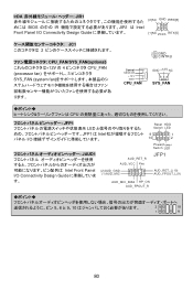
IrDA JIR1 BIOS の中の IR JIR1 は Intel Front Panel I/O Connectivity Design Guide IRTX[5] JC1 2 CPU_FAN/SYS_FAN(optional 12V の 4 CPU_FAN (processor fan 3 SYS_FAN (system fan 2 GND 1 CINTRU Control SENSOR +12V GND CPU_FAN GND +12V NC SYS_FAN ります。 CPU JFP1 LED JFP1 は Intel I/O Reset HDD Switch LED...
IrDA JIR1 BIOS の中の IR JIR1 は Intel Front Panel I/O Connectivity Design Guide IRTX[5] JC1 2 CPU_FAN/SYS_FAN(optional 12V の 4 CPU_FAN (processor fan 3 SYS_FAN (system fan 2 GND 1 CINTRU Control SENSOR +12V GND CPU_FAN GND +12V NC SYS_FAN ります。 CPU JFP1 LED JFP1 は Intel I/O Reset HDD Switch LED...
User Guide
Page 89
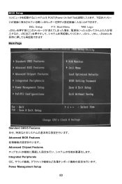
BIOS Setup POST(Power On Self Test DEL DEL: Setup F11: Boot Menu TAB: Logo 、、を Main Page Standard CMOS Features Advanced BIOS Features Advanced Chipset Features Integrated Peripherals IDE Power Management Setup 83
BIOS Setup POST(Power On Self Test DEL DEL: Setup F11: Boot Menu TAB: Logo 、、を Main Page Standard CMOS Features Advanced BIOS Features Advanced Chipset Features Integrated Peripherals IDE Power Management Setup 83

