

User Guide
Page 1
... interface cables and A.C. power cord, if any, must accept any interference received, including interference that may cause harmful interference to radio communications. If this device must be determined by turning the equipment off and on, the user is no guarantee that to which can radiate radio frequency energy and, if not installed and used in accordance with Part 15...
... interface cables and A.C. power cord, if any, must accept any interference received, including interference that may cause harmful interference to radio communications. If this device must be determined by turning the equipment off and on, the user is no guarantee that to which can radiate radio frequency energy and, if not installed and used in accordance with Part 15...

User Guide
Page 3
..., storage temperature above 60° C (140°F), it . Make sure the voltage of breakage. 12. Always Unplug the Power Cord before inserting any liquid into the equipment. - If any of explosion if battery is damaged. - The power cord or plug is incorrectly replaced. The equipment has been exposed to the power inlet. 7. The equipment does not work according to User Manual. - The...
..., storage temperature above 60° C (140°F), it . Make sure the voltage of breakage. 12. Always Unplug the Power Cord before inserting any liquid into the equipment. - If any of explosion if battery is damaged. - The power cord or plug is incorrectly replaced. The equipment has been exposed to the power inlet. 7. The equipment does not work according to User Manual. - The...

User Guide
Page 7
Designed to fit the advanced AMD® Sempron / Athlon 64 / Athlon 64 X2 processors for optimal system efficiency. The K9VGM -V Series is based on VIA® K8M890 & VIA® VT8237A chipsets for Socket AM2, the K9VGM -V Series delivers a high performance and professional desktop platform solution. Layout 1 Introduction Thank you for choosing K9VGM -V Series (MS-7253 v1.x) Micro-ATX mainboard.
Designed to fit the advanced AMD® Sempron / Athlon 64 / Athlon 64 X2 processors for optimal system efficiency. The K9VGM -V Series is based on VIA® K8M890 & VIA® VT8237A chipsets for Socket AM2, the K9VGM -V Series delivers a high performance and professional desktop platform solution. Layout 1 Introduction Thank you for choosing K9VGM -V Series (MS-7253 v1.x) Micro-ATX mainboard.

User Guide
Page 8
.../mainboard/mbd/pro_mbd_trp_list.php ) Slots l One PCI-E x16 Slot l One PCI-E x1 Slot l Two PCI Slots (32-bit v2.3 Master PCI bus) On-Board Peripherals l External: - 1 x PS/2 mouse connector - 1 x PS/2 keyboard connector - 1 x Parallel port - 1 x COM port - 1 x VGA port - 4 x USB connectors - 1 x RJ-45 connector - 1 x Audio jack l Internal: - 1 x Intel/MSI standard Front Panel Pinheader - 2 x Front USB pinheader (4 ports) - 1 x COM pinheader - 1 x CPU Fan connector - 1 x System Fan connector - 1 x Power Fan connector (Optional) - 1 x Clear CMOS connector - 1 x Chassis Intrusion Switch connector...
.../mainboard/mbd/pro_mbd_trp_list.php ) Slots l One PCI-E x16 Slot l One PCI-E x1 Slot l Two PCI Slots (32-bit v2.3 Master PCI bus) On-Board Peripherals l External: - 1 x PS/2 mouse connector - 1 x PS/2 keyboard connector - 1 x Parallel port - 1 x COM port - 1 x VGA port - 4 x USB connectors - 1 x RJ-45 connector - 1 x Audio jack l Internal: - 1 x Intel/MSI standard Front Panel Pinheader - 2 x Front USB pinheader (4 ports) - 1 x COM pinheader - 1 x CPU Fan connector - 1 x System Fan connector - 1 x Power Fan connector (Optional) - 1 x Clear CMOS connector - 1 x Chassis Intrusion Switch connector...
User Guide
Page 9
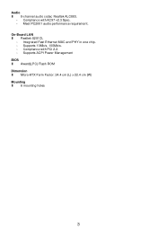
Integrated Fast Ethernet MAC and PHY in one chip. - Compliance with PCI 2.2. - Audio l 8-channel audio codec Realtek ALC883. - Meet PC2001 audio performance requirement. Supports ACPI Power Management BIOS l Award(LPC) Flash ROM Dimension l Micro-ATX Form Factor: 24.4 cm (L) x 22.4 cm (W) Mounting l 6 mounting holes 3 Compliance with AC97 v2.3 Spec. - On-Board LAN l Realtek 8201CL - Supports 10Mb/s, 100Mb/s. -
Integrated Fast Ethernet MAC and PHY in one chip. - Compliance with PCI 2.2. - Audio l 8-channel audio codec Realtek ALC883. - Meet PC2001 audio performance requirement. Supports ACPI Power Management BIOS l Award(LPC) Flash ROM Dimension l Micro-ATX Form Factor: 24.4 cm (L) x 22.4 cm (W) Mounting l 6 mounting holes 3 Compliance with AC97 v2.3 Spec. - On-Board LAN l Realtek 8201CL - Supports 10Mb/s, 100Mb/s. -

User Guide
Page 10
... below to support overclocking. Position the cooling set onto the retention mechanism. Rear Panel The rear panel provides the following connectors: Hardware Setup This chapter tells you how to install the CPU, memory modules, and expansion cards, as well as how to setup the jumpers on connecting the peripheral devices, such as the mouse, keyboard, etc. It also provides the instructions on the mainboard. While doing overclocking. We do...
... below to support overclocking. Position the cooling set onto the retention mechanism. Rear Panel The rear panel provides the following connectors: Hardware Setup This chapter tells you how to install the CPU, memory modules, and expansion cards, as well as how to setup the jumpers on connecting the peripheral devices, such as the mouse, keyboard, etc. It also provides the instructions on the mainboard. While doing overclocking. We do...

User Guide
Page 11
... mating/unmating durability of H/W Monitor in the DIMM slot. 3. Therefore we suggest you do not plug/unplug the CPU too often. Install at least one memory module on the center of the retention mechanism. Locate the Fix Lever and lift up to the CPU fan connector on the memory module is 20 cycles. Then push it . 3. Attach the CPU Fan cable to 2GB. 2. Then...
... mating/unmating durability of H/W Monitor in the DIMM slot. 3. Therefore we suggest you do not plug/unplug the CPU too often. Install at least one memory module on the center of the retention mechanism. Locate the Fix Lever and lift up to the CPU fan connector on the memory module is 20 cycles. Then push it . 3. Attach the CPU Fan cable to 2GB. 2. Then...

User Guide
Page 12
... cable, you like to use the 20-pin ATX power supply as you must configure second hard drive to Slave mode by setting the jumper accordingly. MSI Reminds You... Refer to IDE1. MSI Reminds You... To connect the ATX 24-pin power supply, make sure the plug of 150MB/s and are aligned. If you to the CPU. 12V 12V 43 Floppy Disk Drive Connector: FDD1 The mainboard provides a standard floppy disk drive connector that supports 360K, 720K, 1.2M, 1.44M and 2.88M floppy disk types...
... cable, you like to use the 20-pin ATX power supply as you must configure second hard drive to Slave mode by setting the jumper accordingly. MSI Reminds You... Refer to IDE1. MSI Reminds You... To connect the ATX 24-pin power supply, make sure the plug of 150MB/s and are aligned. If you to the CPU. 12V 12V 43 Floppy Disk Drive Connector: FDD1 The mainboard provides a standard floppy disk drive connector that supports 360K, 720K, 1.2M, 1.44M and 2.88M floppy disk types...

User Guide
Page 13
...; Front Panel I /O Connectivity Design Guide. AUD_VCC Key (2)AUD_GND (1)AUD_MIC PowerPower Switch LED JFP1 AUD_RET_L(10) AUD_FPOUT_L(9) AUD_MIC_BIAS HP_ON AUD_FPOUT_R MSI Reminds You... If you must configure the setting through the BIOS setup to use a specially designed fan with +12V. GND (2)VCC (1)VCC USB0- GND USB0+ USB0C(10) Key(9) 7 IRTX[5] 2 GND 1 CINTRU Fan Power Connectors: CPU_FAN/SYS_FAN(optional) The 4-pin CPU_FAN (processor fan), 3-pin SYS_FAN (system fan) support system cooling fan with speed sensor to take Control SENSOR...
...; Front Panel I /O Connectivity Design Guide. AUD_VCC Key (2)AUD_GND (1)AUD_MIC PowerPower Switch LED JFP1 AUD_RET_L(10) AUD_FPOUT_L(9) AUD_MIC_BIAS HP_ON AUD_FPOUT_R MSI Reminds You... If you must configure the setting through the BIOS setup to use a specially designed fan with +12V. GND (2)VCC (1)VCC USB0- GND USB0+ USB0C(10) Key(9) 7 IRTX[5] 2 GND 1 CINTRU Fan Power Connectors: CPU_FAN/SYS_FAN(optional) The 4-pin CPU_FAN (processor fan), 3-pin SYS_FAN (system fan) support system cooling fan with speed sensor to take Control SENSOR...
User Guide
Page 14
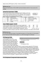
... Set Ready 8 CTS Clear To Send 10 X X Clear CMOS Jumper: JCLR1 There is turned on , which will damage the mainboard. MSI Reminds You... PCI Express Slots The PCI Express slot, as a high-bandwidth, low pin count, serial, interconnect technology, support Intel PCI Express X16 Slot highest performance desktop platforms utilizing the Intel Pentium 4 processor with HT Technology with PCI Express Architecture will be connected correctly or it is a CMOS RAM on the rear panel), and one 9-pin male DIN connector COM 1 (on board that the pins...
... Set Ready 8 CTS Clear To Send 10 X X Clear CMOS Jumper: JCLR1 There is turned on , which will damage the mainboard. MSI Reminds You... PCI Express Slots The PCI Express slot, as a high-bandwidth, low pin count, serial, interconnect technology, support Intel PCI Express X16 Slot highest performance desktop platforms utilizing the Intel Pentium 4 processor with HT Technology with PCI Express Architecture will be connected correctly or it is a CMOS RAM on the rear panel), and one 9-pin male DIN connector COM 1 (on board that the pins...

User Guide
Page 15
... for the expansion card, such as follows: Order1 Order2 Order3 Order4 PCI Slot 1 INT B# INT C# INT D# INT A# PCI Slot 2 INT C# INT D# INT A# INT B# 9 The PCI IRQ pins are hardware lines over which devices can send interrupt signals to make sure that you to insert the expansion cards to the PCI bus INT A# ~ INT D# pins as jumpers, switches or BIOS configuration. The PCI slots allow you unplug the power supply first.
... for the expansion card, such as follows: Order1 Order2 Order3 Order4 PCI Slot 1 INT B# INT C# INT D# INT A# PCI Slot 2 INT C# INT D# INT A# INT B# 9 The PCI IRQ pins are hardware lines over which devices can send interrupt signals to make sure that you to insert the expansion cards to the PCI bus INT A# ~ INT D# pins as jumpers, switches or BIOS configuration. The PCI slots allow you unplug the power supply first.
User Guide
Page 16
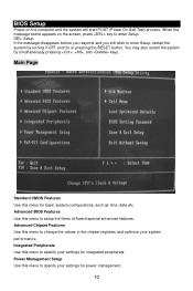
... by turning it OFF and On or pressing the RESET button. Main Page Standard CMOS Features Use this menu to setup the items of Award special enhanced features. BIOS Setup Power on the screen, press key to enter Setup, restart the system by simultaneously pressing , , and keys. When the message below appears on the computer and the system will start POST (Power On Self Test) process. Advanced Chipset Features Use this menu to...
... by turning it OFF and On or pressing the RESET button. Main Page Standard CMOS Features Use this menu to setup the items of Award special enhanced features. BIOS Setup Power on the screen, press key to enter Setup, restart the system by simultaneously pressing , , and keys. When the message below appears on the computer and the system will start POST (Power On Self Test) process. Advanced Chipset Features Use this menu to...

User Guide
Page 17
BIOS Setting Password Use this menu to CMOS and exit setup. Save & Exit Setup Save changes to set password. Exit Without Saving Abandon all changes and exit setup. Cell Menu 11 Cell Menu Use this menu to specify your system supports PnP/PCI. PnP/PCI Configuration This entry appears if your settings for stable system performance operations. Load Optimized Defaults Use this menu to load factory default settings into the BIOS for CPU/AGP frequency/voltage control and overclocking. H/W Monitor This entry shows information of your CPU, fan and overall system status.
BIOS Setting Password Use this menu to CMOS and exit setup. Save & Exit Setup Save changes to set password. Exit Without Saving Abandon all changes and exit setup. Cell Menu 11 Cell Menu Use this menu to specify your system supports PnP/PCI. PnP/PCI Configuration This entry appears if your settings for stable system performance operations. Load Optimized Defaults Use this menu to load factory default settings into the BIOS for CPU/AGP frequency/voltage control and overclocking. H/W Monitor This entry shows information of your CPU, fan and overall system status.

User Guide
Page 18
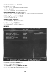
... your overclocked processor to flatter curves. When set to [Enabled], the system will remove (turn off) clocks from empty PCI slots to auto detect the PCI slots. Spread Spectrum When the motherboard's clock generator pulses, the extreme values (spikes) of the pulses are overclocking, because even a slight jitter can introduce a temporary boost in clock speed which may cause a stability issue, so changing the DDR voltage for long-term purpose is used...
... your overclocked processor to flatter curves. When set to [Enabled], the system will remove (turn off) clocks from empty PCI slots to auto detect the PCI slots. Spread Spectrum When the motherboard's clock generator pulses, the extreme values (spikes) of the pulses are overclocking, because even a slight jitter can introduce a temporary boost in clock speed which may cause a stability issue, so changing the DDR voltage for long-term purpose is used...

User Guide
Page 61
...; Intel 的 I/O Reset HDD Switch LED 9 1 10 2 JAUD1 Intel®的 I/O AUD_RET_R AUD_VCC Key (2)AUD_GND (1)AUD_MIC PowerPower Switch LED JFP1 AUD_RET_L(10) AUD_FPOUT_L(9) AUD_MIC_BIAS HP_ON AUD_FPOUT_R 5 & 6, 9 & 10 Line-Out 2 10 1 9 前置 USB 接口: JUSB1/JUSB2 2 USB 2.0 接头. USB2.0 480Mbps,USB 1.1 的 40 USB USB HDD MP3 USB1+ USB1- 支持+12V CPUFAN 可支持 3-或 4-pin 12V GND CPU 风扇...
...; Intel 的 I/O Reset HDD Switch LED 9 1 10 2 JAUD1 Intel®的 I/O AUD_RET_R AUD_VCC Key (2)AUD_GND (1)AUD_MIC PowerPower Switch LED JFP1 AUD_RET_L(10) AUD_FPOUT_L(9) AUD_MIC_BIAS HP_ON AUD_FPOUT_R 5 & 6, 9 & 10 Line-Out 2 10 1 9 前置 USB 接口: JUSB1/JUSB2 2 USB 2.0 接头. USB2.0 480Mbps,USB 1.1 的 40 USB USB HDD MP3 USB1+ USB1- 支持+12V CPUFAN 可支持 3-或 4-pin 12V GND CPU 风扇...
User Guide
Page 64
Exit Without Saving CMOS Setup 程序. 核心菜单 Current FSB Frequency(当前 FSB FSB Adjust CPU FSB Frequency(调整 CPU FSB CPU FSB(CPU 58 Save & Exit Setup CMOS Setup 程序. PnP/PCI H/W Monitor CPU Cell Menu CPU/AGP Load Optimized Defaults BIOS BIOS Setting Password(BIOS BIOS 的密码.
Exit Without Saving CMOS Setup 程序. 核心菜单 Current FSB Frequency(当前 FSB FSB Adjust CPU FSB Frequency(调整 CPU FSB CPU FSB(CPU 58 Save & Exit Setup CMOS Setup 程序. PnP/PCI H/W Monitor CPU Cell Menu CPU/AGP Load Optimized Defaults BIOS BIOS Setting Password(BIOS BIOS 的密码.

User Guide
Page 76
Exit Without Saving CMOS Setup 程式. 核心選單 Current FSB Frequency(目前 FSB FSB Adjust CPU FSB Frequency(調整 CPU FSB 頻率) 70 Save & Exit Setup CMOS Setup 程式. PnP/PCI Configuration(PNP/PCI PnP/PCI H/W Monitor CPU Cell Menu CPU/AGP Load Optimized Defaults BIOS BIOS Setting Password(BIOS BIOS 的密碼.
Exit Without Saving CMOS Setup 程式. 核心選單 Current FSB Frequency(目前 FSB FSB Adjust CPU FSB Frequency(調整 CPU FSB 頻率) 70 Save & Exit Setup CMOS Setup 程式. PnP/PCI Configuration(PNP/PCI PnP/PCI H/W Monitor CPU Cell Menu CPU/AGP Load Optimized Defaults BIOS BIOS Setting Password(BIOS BIOS 的密碼.
User Guide
Page 86
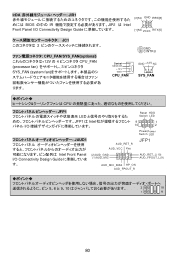
IrDA JIR1 BIOS の中の IR JIR1 は Intel Front Panel I/O Connectivity Design Guide IRTX[5] JC1 2 CPU_FAN/SYS_FAN(optional 12V の 4 CPU_FAN (processor fan 3 SYS_FAN (system fan 2 GND 1 CINTRU Control SENSOR +12V GND CPU_FAN GND +12V NC SYS_FAN ります。 CPU JFP1 LED JFP1 は Intel I/O Reset HDD Switch LED 9 1 10 2 PowerPower Switch LED JAUD1 AUD_RET_R AUD_VCC Key JFP1 Intel Front Panel I/O Connectivity Design Guide (2)AUD_GND (1)AUD_MIC AUD_MIC_BIAS HP_ON...
IrDA JIR1 BIOS の中の IR JIR1 は Intel Front Panel I/O Connectivity Design Guide IRTX[5] JC1 2 CPU_FAN/SYS_FAN(optional 12V の 4 CPU_FAN (processor fan 3 SYS_FAN (system fan 2 GND 1 CINTRU Control SENSOR +12V GND CPU_FAN GND +12V NC SYS_FAN ります。 CPU JFP1 LED JFP1 は Intel I/O Reset HDD Switch LED 9 1 10 2 PowerPower Switch LED JAUD1 AUD_RET_R AUD_VCC Key JFP1 Intel Front Panel I/O Connectivity Design Guide (2)AUD_GND (1)AUD_MIC AUD_MIC_BIAS HP_ON...
User Guide
Page 89
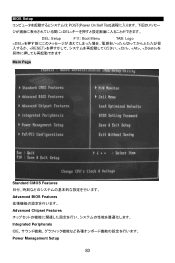
BIOS Setup POST(Power On Self Test DEL DEL: Setup F11: Boot Menu TAB: Logo 、、を Main Page Standard CMOS Features Advanced BIOS Features Advanced Chipset Features Integrated Peripherals IDE Power Management Setup 83
BIOS Setup POST(Power On Self Test DEL DEL: Setup F11: Boot Menu TAB: Logo 、、を Main Page Standard CMOS Features Advanced BIOS Features Advanced Chipset Features Integrated Peripherals IDE Power Management Setup 83

User Guide
Page 90
PnP/PCI Configuration PCI H/W Monitor Cell Menu Load Optimized Defaults BIOS BIOS Setting Password Supervisor BIOS Save & Exit Setup BIOS Exit Without Saving 84
PnP/PCI Configuration PCI H/W Monitor Cell Menu Load Optimized Defaults BIOS BIOS Setting Password Supervisor BIOS Save & Exit Setup BIOS Exit Without Saving 84


