
MSI K9VGM Support Question
MSI K9VGM Support Question
Find answers below for this question about MSI K9VGM.Need a MSI K9VGM manual? We have 1 online manual for this item!
Question posted by marquomarshall686 on May 22nd, 2017
Computer Keeps Making The Error Sound When I Switch On The Pc
it just keeps on making that sound and doesn't go any further not even lading windows
Current Answers
Answer #1: Posted by BusterDoogen on May 22nd, 2017 9:24 AM
BusterDoogen

Member since:
October 30th, 2011 Points: 28,565,407

Member since:
October 30th, 2011 Points: 28,565,407
It's likely your ram. Make sure it's seated properly. Also make sure your video card is seated properly as well. If it persists, try using only 1 memory module at a time.
I hope this is helpful to you!
Please respond to my effort to provide you with the best possible solution by using the "Acceptable Solution" and/or the "Helpful" buttons when the answer has proven to be helpful. Please feel free to submit further info for your question, if a solution was not provided. I appreciate the opportunity to serve you!
Related MSI K9VGM Manual Pages
User Guide - Page 2

... other countries. Intel® and Pentium® are registered trademarks of Microsoft Corporation. Windows® 98/2000/NT/XP are registered trademarks of the Kensington Technology Group. Revision ... The material in this document, but no guarantee is given as to make changes without notice. Trademarks All trademarks are under continual improvement and we reserve the right to...
User Guide - Page 3

...8. The power cord or plug is incorrectly replaced. CAUTION: Danger of breakage. 12. Keep this equipment away from overheating. Always Unplug the Power Cord before connecting the
equipment to... inlet. 7. The equipment does not work according to User Manual. - Safety Instructions
1.
Make sure the voltage of the following situations arises, get it . Place the power cord such...
User Guide - Page 7

... the advanced AMD® Sempron / Athlon 64 / Athlon 64 X2 processors for choosing K9VGM -V Series (MS-7253 v1.x) Micro-ATX mainboard.
Introduction
Thank you for Socket AM2, the K9VGM -V Series delivers a high performance and professional desktop platform solution. Layout
1 The K9VGM -V Series is based on VIA® K8M890 & VIA® VT8237A chipsets for...
User Guide - Page 8

... standard Front Panel Pinheader - 2 x Front USB pinheader (4 ports) - 1 x COM pinheader - 1 x CPU Fan connector - 1 x System Fan connector - 1 x Power Fan connector (Optional) - 1 x Clear CMOS connector - 1 x Chassis Intrusion Switch connector - 1 x Intel® Front Audio pinheader - 2 x IDE(ATA133) connectors - 1 x Floppy connector - 1 x CD-in connector - 2 x SATA connectors
2
User Guide - Page 10

...Athlon64 X2/ Athlon64 & Athlon FX processors. Overclocking This motherboard is not recommended. However, please make sure your components are installing the CPU, make sure the cooling fan can work properly to operate ...able to support overclocking. Wrong installation will seriously damage the CPU and system, always make sure the CPU has a cooler attached on the top to apply some silicon heat...
User Guide - Page 11

... fan connector on the center of the CPU is deeply inserted in the right orientation.
2. Memory modules can install either single-
Check the information in PC Health Status of the DIMM slot will only fit in the DIMM slot.
3. Installing DDR II Modules
Volt
Notch
1. You can be installed. The memory...
User Guide - Page 12

... Master, and Ultra DMA 66/100/133 function. You can connect up to IDE1. MSI Reminds You...
To connect the ATX 24-pin power supply, make sure the plug of 150MB/s and are aligned. Refer to the hard disk documentation supplied by hard disk vendors for CD-ROM audio connector. Then...
User Guide - Page 13

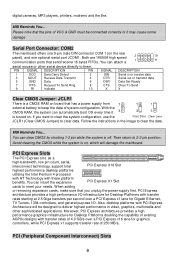
... module and is compliant with Intel® Front Panel I/O Connectivity Design Guide. Chassis Intrusion Switch Connector: JC1
This connector is compliant with Intel® Front Panel I /O Connectivity Design ...the front panel audio and is Ground and should be connected to a 2-pin chassis switch.
Front USB Connector: JUSB1/JUSB2
The mainboard provides two standard USB 2.0 pin headers ...
User Guide - Page 14
...X
X
Clear CMOS Jumper: JCLR1
There is on .
When adding
or removing expansion cards, make sure that send/receive 16 bytes FIFOs. Please note that has a power supply from external ... designed to deliver highest performance in video, graphics, multimedia and
other serial device directly to keep the data of system configuration. PCI Express Slots
The PCI Express slot, as a
high-...
User Guide - Page 15

...are typically connected to the PCI bus INT A# ~ INT D# pins as jumpers, switches or BIOS configuration.
The PCI slots allow you unplug the power supply first. Meanwhile, ...D#
INT A#
INT B#
9 When adding or removing expansion cards, make any necessary hardware or software settings for the expansion card to make sure that you to insert the expansion cards to the microprocessor. The...
User Guide - Page 18

Spread Spectrum When the motherboard's clock generator pulses, the extreme values (spikes) of the pulses are reduced to flatter curves....stability issue, so changing the DDR voltage for optimal system stability and performance. Any changes made to this setting may just cause your overclocked processor to auto detect the PCI slots. The Spread Spectrum function reduces the EMI generated by EMI...
User Guide - Page 61

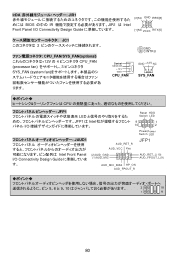
...;持 3-或 4-pin 12V GND CPU 风扇. JFP1
JFP1 是和 Intel 的 I/O
Reset HDD Switch LED
9
1
10
2
JAUD1
Intel®的 I/O
AUD_RET_R AUD_VCC Key
(2)AUD_GND (1)AUD_MIC
PowerPower Switch LED
JFP1
AUD_RET_L(10) AUD_FPOUT_L(9)
AUD_MIC_BIAS HP_ON AUD_FPOUT_R
5 & 6, 9 & 10
Line-Out
2
10
1
9
前置 USB 接...
User Guide - Page 73

GND
(2)VCC (1)VCC
USB0- JFP1
JFP1 是和 Intel 的 I/O
Reset HDD Switch LED
9
1
10
2
JAUD1
Intel®的 I/O
AUD_RET_R AUD_VCC Key
(2)AUD_GND (1)AUD_MIC
PowerPower Switch LED
JFP1
AUD_RET_L(10) AUD_FPOUT_L(9)
AUD_MIC_BIAS HP_ON AUD_FPOUT_R
5 & 6, 9 & 10
Line-Out
2
10
1
9
前置 USB 介面: JUSB1/JUSB2
2 USB 2.0 ...
User Guide - Page 86
...
Control SENSOR
+12V GND
CPU_FAN
GND +12V NC
SYS_FAN
ります。
CPU
JFP1 LED JFP1 は Intel I/O
Reset HDD Switch LED
9
1
10
2
PowerPower Switch LED
JAUD1
AUD_RET_R AUD_VCC Key
JFP1
Intel Front Panel I/O Connectivity Design Guide
(2)AUD_GND (1)AUD_MIC
AUD_MIC_BIAS HP_ON AUD_FPOUT_R
AUD_RET_L(10) AUD_FPOUT_L(9)
5、6 と...
Similar Questions

Would My Ide Cable Stop My Pc From Starting Even Though I Could Use Both Connect
i tried the method of taking off everything until it was just left the CPU and it still did the same...
i tried the method of taking off everything until it was just left the CPU and it still did the same...
(Posted by marquomarshall686 6 years ago)

Vga Driver For Windows 7
i have a problem with my ms 7253 vga driver,how can i fix it?
i have a problem with my ms 7253 vga driver,how can i fix it?
(Posted by jhones16 9 years ago)

Vga Driver For Windows7
i am unable to find the drivers for vga for windows7
i am unable to find the drivers for vga for windows7
(Posted by anilhisar 11 years ago)

Graphic Card
can i use a EVGA GeForce 6800 GS GDDR3 ON A MSI Motherboard, because its makes little sounds when i...
can i use a EVGA GeForce 6800 GS GDDR3 ON A MSI Motherboard, because its makes little sounds when i...
(Posted by reload70 12 years ago)

Msi K9n6pgm2 Motherboard Sound Problem
My motherboard has a built in grapichs card and I installed the windows xp OS onto it and put the dr...
My motherboard has a built in grapichs card and I installed the windows xp OS onto it and put the dr...
(Posted by kungfumasterleopold 13 years ago)