
User Guide
Page 9
Compliance with PCI 2.2. - Supports ACPI Power Management BIOS l Award(LPC) Flash ROM Dimension l Micro-ATX Form Factor: 24.4 cm (L) x 22.4 cm (W) Mounting l 6 mounting holes 3 Meet PC2001 audio performance requirement. Compliance with AC97 v2.3 Spec. - Integrated Fast Ethernet MAC and PHY in one chip. - On-Board LAN l Realtek 8201CL - Supports 10Mb/s, 100Mb/s. - Audio l 8-channel audio codec Realtek ALC883. -
Compliance with PCI 2.2. - Supports ACPI Power Management BIOS l Award(LPC) Flash ROM Dimension l Micro-ATX Form Factor: 24.4 cm (L) x 22.4 cm (W) Mounting l 6 mounting holes 3 Meet PC2001 audio performance requirement. Compliance with AC97 v2.3 Spec. - Integrated Fast Ethernet MAC and PHY in one chip. - On-Board LAN l Realtek 8201CL - Supports 10Mb/s, 100Mb/s. - Audio l 8-channel audio codec Realtek ALC883. -

User Guide
Page 11
... 667 / 800 DIMM slots, and supports the memory size up it in until the golden finger on the memory module is deeply inserted in BIOS for the CPU temperature. 3. Insert the memory module vertically into the DIMM slot. The plastic clip at least one memory module on your own... The memory module will automatically close. 5 2. Then press down the lever. 4. Locate the Fix Lever and lift up to meet your system. 2. MSI Reminds You... 1. To operate properly, at least one notch on the slots in the right orientation. 2. Memory modules can install either single- You can ...
... 667 / 800 DIMM slots, and supports the memory size up it in until the golden finger on the memory module is deeply inserted in BIOS for the CPU temperature. 3. Insert the memory module vertically into the DIMM slot. The plastic clip at least one memory module on your own... The memory module will automatically close. 5 2. Then press down the lever. 4. Locate the Fix Lever and lift up to meet your system. 2. MSI Reminds You... 1. To operate properly, at least one notch on the slots in the right orientation. 2. Memory modules can install either single- You can ...

User Guide
Page 13
...peripherals such as USB HDD, USB1+ USB1- AUD_VCC Key (2)AUD_GND (1)AUD_MIC PowerPower Switch LED JFP1 AUD_RET_L(10) AUD_FPOUT_L(9) AUD_MIC_BIAS HP_ON AUD_FPOUT_R MSI Reminds You... USB2.0 technology increases data transfer rate up to a maximum throughput of the CPU fan control. Chassis Intrusion Switch Connector: ...with Intel® Front Panel I/O Connectivity Design Guide. JFP1 is compliant with +12V. If you must configure the setting through the BIOS setup to use a specially designed fan with speed sensor to take Control SENSOR +12V GND CPU_FAN GND +12V NC SYS_FAN note ...
...peripherals such as USB HDD, USB1+ USB1- AUD_VCC Key (2)AUD_GND (1)AUD_MIC PowerPower Switch LED JFP1 AUD_RET_L(10) AUD_FPOUT_L(9) AUD_MIC_BIAS HP_ON AUD_FPOUT_R MSI Reminds You... USB2.0 technology increases data transfer rate up to a maximum throughput of the CPU fan control. Chassis Intrusion Switch Connector: ...with Intel® Front Panel I/O Connectivity Design Guide. JFP1 is compliant with +12V. If you must configure the setting through the BIOS setup to use a specially designed fan with speed sensor to take Control SENSOR +12V GND CPU_FAN GND +12V NC SYS_FAN note ...

User Guide
Page 15
... Request Routing The IRQ, abbreviation of interrupt request line and pronounced I-R-Q, are typically connected to the PCI bus INT A# ~ INT D# pins as jumpers, switches or BIOS configuration. The PCI IRQ pins are hardware lines over which devices can send interrupt signals to meet your needs. Meanwhile, read the documentation for the...
... Request Routing The IRQ, abbreviation of interrupt request line and pronounced I-R-Q, are typically connected to the PCI bus INT A# ~ INT D# pins as jumpers, switches or BIOS configuration. The PCI IRQ pins are hardware lines over which devices can send interrupt signals to meet your needs. Meanwhile, read the documentation for the...
User Guide
Page 16
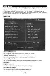
... , , and keys. You may also restart the system by turning it OFF and On or pressing the RESET button. BIOS Setup Power on the screen, press key to enter Setup. Advanced BIOS Features Use this menu to specify your system performance. When the message below appears on the computer and the system...
... , , and keys. You may also restart the system by turning it OFF and On or pressing the RESET button. BIOS Setup Power on the screen, press key to enter Setup. Advanced BIOS Features Use this menu to specify your system performance. When the message below appears on the computer and the system...

User Guide
Page 17
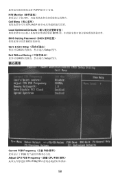
PnP/PCI Configuration This entry appears if your CPU, fan and overall system status. BIOS Setting Password Use this menu to specify your settings for stable system performance operations. H/W Monitor This entry shows information of your system supports PnP/PCI. Cell Menu Use this menu to load factory default settings into the BIOS for CPU/AGP frequency/voltage control and overclocking. Save & Exit Setup Save changes to set password. Load Optimized Defaults Use this menu to CMOS and exit setup. Exit Without Saving Abandon all changes and exit setup. Cell Menu 11
PnP/PCI Configuration This entry appears if your CPU, fan and overall system status. BIOS Setting Password Use this menu to specify your settings for stable system performance operations. H/W Monitor This entry shows information of your system supports PnP/PCI. Cell Menu Use this menu to load factory default settings into the BIOS for CPU/AGP frequency/voltage control and overclocking. Save & Exit Setup Save changes to set password. Load Optimized Defaults Use this menu to CMOS and exit setup. Exit Without Saving Abandon all changes and exit setup. Cell Menu 11

User Guide
Page 59
DDR II DIMM 2. 将 DIMM DIMM 3. DIMM ATX 24-Pin ATX1 ATX ATX 20-pin ATX 20-pin ATX pin 1 和 pin 13 pin 11, 12, 23 和 24 +3.3V -12V GND PS-ON# GND GND GND Res +5V +5V +5V GND 13 1 24 12 +3.3V +3.3V GND +5V GND +5V GND PWR OK 5VSB +12V +12V NC 53 2 3 4. 将 CPU CPU 1 CPU 2. 在 BIOS CPU CPU 的温度. 3. 请注意 CPU 20 CPU. 内存 2 条 240-pin DDR II 400 / 533 / 667 / 800 DIMM 2GB 1 条 DIMM 1 条 DIMM Volt Notch 1.
DDR II DIMM 2. 将 DIMM DIMM 3. DIMM ATX 24-Pin ATX1 ATX ATX 20-pin ATX 20-pin ATX pin 1 和 pin 13 pin 11, 12, 23 和 24 +3.3V -12V GND PS-ON# GND GND GND Res +5V +5V +5V GND 13 1 24 12 +3.3V +3.3V GND +5V GND +5V GND PWR OK 5VSB +12V +12V NC 53 2 3 4. 将 CPU CPU 1 CPU 2. 在 BIOS CPU CPU 的温度. 3. 请注意 CPU 20 CPU. 内存 2 条 240-pin DDR II 400 / 533 / 667 / 800 DIMM 2GB 1 条 DIMM 1 条 DIMM Volt Notch 1.
User Guide
Page 64
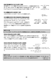
Exit Without Saving CMOS Setup 程序. 核心菜单 Current FSB Frequency(当前 FSB FSB Adjust CPU FSB Frequency(调整 CPU FSB CPU FSB(CPU 58 PnP/PCI H/W Monitor CPU Cell Menu CPU/AGP Load Optimized Defaults BIOS BIOS Setting Password(BIOS BIOS 的密码. Save & Exit Setup CMOS Setup 程序.
Exit Without Saving CMOS Setup 程序. 核心菜单 Current FSB Frequency(当前 FSB FSB Adjust CPU FSB Frequency(调整 CPU FSB CPU FSB(CPU 58 PnP/PCI H/W Monitor CPU Cell Menu CPU/AGP Load Optimized Defaults BIOS BIOS Setting Password(BIOS BIOS 的密码. Save & Exit Setup CMOS Setup 程序.

User Guide
Page 71
DDR II DIMM 2. 將 DIMM DIMM 3. DIMM ATX 24-Pin ATX1 ATX ATX 20-pin ATX 20-pin ATX +3.3V -12V GND PS-ON# GND GND GND Res +5V +5V +5V GND 13 1 24 12 +3.3V +3.3V GND +5V GND +5V GND PWR OK 5VSB +12V +12V NC 65 2 3 4. 將 CPU CPU 1 CPU 2. 在 BIOS CPU CPU 的溫度. 3. 請注意 CPU 20 CPU. 記憶體 2 條 240-pin DDR II 400 / 533 / 667 / 800 DIMM 2GB 1 條 DIMM 1 條 DIMM Volt Notch 1.
DDR II DIMM 2. 將 DIMM DIMM 3. DIMM ATX 24-Pin ATX1 ATX ATX 20-pin ATX 20-pin ATX +3.3V -12V GND PS-ON# GND GND GND Res +5V +5V +5V GND 13 1 24 12 +3.3V +3.3V GND +5V GND +5V GND PWR OK 5VSB +12V +12V NC 65 2 3 4. 將 CPU CPU 1 CPU 2. 在 BIOS CPU CPU 的溫度. 3. 請注意 CPU 20 CPU. 記憶體 2 條 240-pin DDR II 400 / 533 / 667 / 800 DIMM 2GB 1 條 DIMM 1 條 DIMM Volt Notch 1.

User Guide
Page 74
PCI PCI BIOS 設置. PCI Express PCI Express X16 Slot PCI Express I/O 秒 2.5 GB,PCI Express x1 可安裝 Gigabit PCI Express X1 Slot Ethernet&#...
PCI PCI BIOS 設置. PCI Express PCI Express X16 Slot PCI Express I/O 秒 2.5 GB,PCI Express x1 可安裝 Gigabit PCI Express X1 Slot Ethernet&#...

User Guide
Page 76
PnP/PCI Configuration(PNP/PCI PnP/PCI H/W Monitor CPU Cell Menu CPU/AGP Load Optimized Defaults BIOS BIOS Setting Password(BIOS BIOS 的密碼. Exit Without Saving CMOS Setup 程式. 核心選單 Current FSB Frequency(目前 FSB FSB Adjust CPU FSB Frequency(調整 CPU FSB 頻率) 70 Save & Exit Setup CMOS Setup 程式.
PnP/PCI Configuration(PNP/PCI PnP/PCI H/W Monitor CPU Cell Menu CPU/AGP Load Optimized Defaults BIOS BIOS Setting Password(BIOS BIOS 的密碼. Exit Without Saving CMOS Setup 程式. 核心選單 Current FSB Frequency(目前 FSB FSB Adjust CPU FSB Frequency(調整 CPU FSB 頻率) 70 Save & Exit Setup CMOS Setup 程式.
User Guide
Page 86
IrDA JIR1 BIOS の中の IR JIR1 は Intel Front Panel I/O Connectivity Design Guide IRTX[5] JC1 2 CPU_FAN/SYS_FAN(optional 12V の 4 CPU_FAN (processor fan 3 SYS_FAN (system fan 2 ...
IrDA JIR1 BIOS の中の IR JIR1 は Intel Front Panel I/O Connectivity Design Guide IRTX[5] JC1 2 CPU_FAN/SYS_FAN(optional 12V の 4 CPU_FAN (processor fan 3 SYS_FAN (system fan 2 ...
User Guide
Page 89
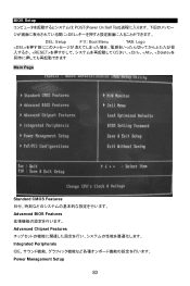
BIOS Setup POST(Power On Self Test DEL DEL: Setup F11: Boot Menu TAB: Logo 、、を Main Page Standard CMOS Features Advanced BIOS Features Advanced Chipset Features Integrated Peripherals IDE Power Management Setup 83
BIOS Setup POST(Power On Self Test DEL DEL: Setup F11: Boot Menu TAB: Logo 、、を Main Page Standard CMOS Features Advanced BIOS Features Advanced Chipset Features Integrated Peripherals IDE Power Management Setup 83

User Guide
Page 90
PnP/PCI Configuration PCI H/W Monitor Cell Menu Load Optimized Defaults BIOS BIOS Setting Password Supervisor BIOS Save & Exit Setup BIOS Exit Without Saving 84
PnP/PCI Configuration PCI H/W Monitor Cell Menu Load Optimized Defaults BIOS BIOS Setting Password Supervisor BIOS Save & Exit Setup BIOS Exit Without Saving 84


