
User Guide
Page 3
.... If any add-on card or module. 9. Replace only with the same or equivalent type recommended by a service personnel: - Keep this equipment in an environment unconditioned, storage temperature above 60° C (140°F), it up. 5. Always Unplug the Power Cord before inserting any of the power source and adjust properly 110/220V before setting it may damage the equipment...
.... If any add-on card or module. 9. Replace only with the same or equivalent type recommended by a service personnel: - Keep this equipment in an environment unconditioned, storage temperature above 60° C (140°F), it up. 5. Always Unplug the Power Cord before inserting any of the power source and adjust properly 110/220V before setting it may damage the equipment...

User Guide
Page 7
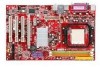
....x) ATX mainboard. Supports the AMD® Socket-AM2 processor, the K9N4 Ultra series delivers a high performance and professional desktop platform solution. Out B:Mic-In JPW1 JWR1 JSP1 SFAN1 JCI1 Winbond W83627EHG PCI _E1 BIOS J1 ALC665 JAUD1 PCI _E2 PCI 1 PCI 2 PCI 3 1 DIMM1 DIMM2 BATT + JUSB1 JUSB2 JBAT1 FDD 1 JFP1 JFP2 Introduction Thank you for optimal system efficiency. Layout Top : mouse Bottom: keyboard CFAN1 Top : Parallel Port Bottom: COM 1 IDE 1 SATA3...
....x) ATX mainboard. Supports the AMD® Socket-AM2 processor, the K9N4 Ultra series delivers a high performance and professional desktop platform solution. Out B:Mic-In JPW1 JWR1 JSP1 SFAN1 JCI1 Winbond W83627EHG PCI _E1 BIOS J1 ALC665 JAUD1 PCI _E2 PCI 1 PCI 2 PCI 3 1 DIMM1 DIMM2 BATT + JUSB1 JUSB2 JBAT1 FDD 1 JFP1 JFP2 Introduction Thank you for optimal system efficiency. Layout Top : mouse Bottom: keyboard CFAN1 Top : Parallel Port Bottom: COM 1 IDE 1 SATA3...

User Guide
Page 8
... (optional) Audio • 5.1 channel audio codec Realtek ALC655 • Compliance with AC97 v2.3 Spec • Meet PC2001 audio performance requirement IDE • 1 IDE controller on the nVIDIA nForce 500 Ultra chipset provides IDE HDD/ CD-ROM with PIO, Bus Master and Ultra DMA 133/100/66 operation modes • Can connect up to 2 IDE devices SATA • Supports 4 SATAII ports with up to 300MB/s transfer rate • Supports up to 4 SATAII HD RAID • Supports RAID 0, 1, 0+1 Floppy • 1 floppy port...
... (optional) Audio • 5.1 channel audio codec Realtek ALC655 • Compliance with AC97 v2.3 Spec • Meet PC2001 audio performance requirement IDE • 1 IDE controller on the nVIDIA nForce 500 Ultra chipset provides IDE HDD/ CD-ROM with PIO, Bus Master and Ultra DMA 133/100/66 operation modes • Can connect up to 2 IDE devices SATA • Supports 4 SATAII ports with up to 300MB/s transfer rate • Supports up to 4 SATAII HD RAID • Supports RAID 0, 1, 0+1 Floppy • 1 floppy port...

User Guide
Page 9
- 1 PS/2 keyboard port - 1 serial port (COM1) - 1 parallel port supporting SPP/EPP/ECP mode - 4 USB 2.0 Ports - 1 RJ-45 LAN Jack - 1 Audio (Line-In / Line-Out/ MIC) port • On-Board Pinheaders - 2 USB 2.0 pinheaders - 2 Fan connectors Slots • 1 PCI Express x16 slot • 1 PCI Express x1 slot • 3 PCI slots (support 3.3V/ 5V PCI bus Interface) Form Factor • ATX (30.4cm X 18.5cm) Mounting • 6 mounting holes 3
- 1 PS/2 keyboard port - 1 serial port (COM1) - 1 parallel port supporting SPP/EPP/ECP mode - 4 USB 2.0 Ports - 1 RJ-45 LAN Jack - 1 Audio (Line-In / Line-Out/ MIC) port • On-Board Pinheaders - 2 USB 2.0 pinheaders - 2 Fan connectors Slots • 1 PCI Express x16 slot • 1 PCI Express x1 slot • 3 PCI slots (support 3.3V/ 5V PCI bus Interface) Form Factor • ATX (30.4cm X 18.5cm) Mounting • 6 mounting holes 3

User Guide
Page 10
Central Processing Unit: CPU The mainboard supports AMD® Athlon64 X2 / Athlon64 / Sempron processors. The mainboard uses a CPU socket called Socket AM2(940-pin) for better heat dispersion. Any attempt to operate beyond product specifications. Wrong installation will seriously damage the CPU and system; It also provides the instructions on connecting the peripheral devices, such as how to setup the jumpers on the mainboard. always make sure the CPU has a cooler attached...
Central Processing Unit: CPU The mainboard supports AMD® Athlon64 X2 / Athlon64 / Sempron processors. The mainboard uses a CPU socket called Socket AM2(940-pin) for better heat dispersion. Any attempt to operate beyond product specifications. Wrong installation will seriously damage the CPU and system; It also provides the instructions on connecting the peripheral devices, such as how to setup the jumpers on the mainboard. always make sure the CPU has a cooler attached...

User Guide
Page 11
...installed before turning on the slots in any order. Attach the CPU Fan cable to fasten the cooling set onto the retention mechanism. You can be installed. MSI Reminds You... 1. The DDR II DIMM has only one Memory module on the mainboard. Then press down the lever. 4. Confirm if your own needs. Locate...we suggest you do not plug/unplug the CPU too often. To operate properly, at least one notch on the top of the slots. Installing DDR II Modules Volt Notch 1. Memory The mainboard provides two 240-pin DIMM slots for the CPU temperature. 3. Check the information...
...installed before turning on the slots in any order. Attach the CPU Fan cable to fasten the cooling set onto the retention mechanism. You can be installed. MSI Reminds You... 1. The DDR II DIMM has only one Memory module on the mainboard. Then press down the lever. 4. Confirm if your own needs. Locate...we suggest you do not plug/unplug the CPU too often. To operate properly, at least one notch on the top of the slots. Installing DDR II Modules Volt Notch 1. Memory The mainboard provides two 240-pin DIMM slots for the CPU temperature. 3. Check the information...

User Guide
Page 12
... used to provide power to the hard disk documentation supplied by setting the jumper accordingly. GND 12V 24 Floppy Disk Drive Connector: FDD1 The mainboard provides a standard floppy disk drive connector that supports 360K, 720K, 1.2M, 1.44M and 2.88M floppy disk types. You must configure the second drive to connect an ATX 24-pin power supply. Power Supply The mainboard supports ATX power supply for jumper setting instructions. 6 Then push down the power supply firmly into the DIMM slot. If you install two hard disks on one cable, you to Slave mode by setting its jumper...
... used to provide power to the hard disk documentation supplied by setting the jumper accordingly. GND 12V 24 Floppy Disk Drive Connector: FDD1 The mainboard provides a standard floppy disk drive connector that supports 360K, 720K, 1.2M, 1.44M and 2.88M floppy disk types. You must configure the second drive to connect an ATX 24-pin power supply. Power Supply The mainboard supports ATX power supply for jumper setting instructions. 6 Then push down the power supply firmly into the DIMM slot. If you install two hard disks on one cable, you to Slave mode by setting its jumper...

User Guide
Page 13
... 3-pin CFAN1 (processor fan) and SFAN1 (system fan) support system Sensor +12V cooling fan with Intel® Front Panel I /O Connectivity Design Guide. JFP1, JFP2 is connected to 1 hard disk device. CD In Connector: J1 R The connector is for electrical connection to the front panel audio and is Ground and should be connected to the +12V, the black wire is compliant with +12V. Reset HDD Switch LED 9 17 10 28 Power LED 1 2 PowerPower Switch LED JFP1 Speaker JFP2 Front Panel Audio Connector: JAUD1...
... 3-pin CFAN1 (processor fan) and SFAN1 (system fan) support system Sensor +12V cooling fan with Intel® Front Panel I /O Connectivity Design Guide. JFP1, JFP2 is connected to 1 hard disk device. CD In Connector: J1 R The connector is for electrical connection to the front panel audio and is Ground and should be connected to the +12V, the black wire is compliant with +12V. Reset HDD Switch LED 9 17 10 28 Power LED 1 2 PowerPower Switch LED JFP1 Speaker JFP2 Front Panel Audio Connector: JAUD1...

User Guide
Page 14
... rear audio ports. 2 1 10 9 Otherwise, the Line-Out connector on board that the pins of system configuration. MSI Reminds You... Clear CMOS Jumper: JBAT1 There is a CMOS RAM on the back panel will not function. Follow the instructions in order to have signal output directed to clear the data. Front USB Connector: JUSB1/JUSB2 The mainboard provides three standard USB 2.0 pin headers JUSB1 and JUSB2. PCI Express X16 Slot PCI Express architecture provides a high performance I/O infrastructure for Desktop...
... rear audio ports. 2 1 10 9 Otherwise, the Line-Out connector on board that the pins of system configuration. MSI Reminds You... Clear CMOS Jumper: JBAT1 There is a CMOS RAM on the back panel will not function. Follow the instructions in order to have signal output directed to clear the data. Front USB Connector: JUSB1/JUSB2 The mainboard provides three standard USB 2.0 pin headers JUSB1 and JUSB2. PCI Express X16 Slot PCI Express architecture provides a high performance I/O infrastructure for Desktop...

User Guide
Page 15
... cards to the PCI bus INT A# ~ INT D# pins as jumpers, switches or BIOS configuration. PCI (Peripheral Component Interconnect) Slots The PCI slots allow you unplug the power supply first. Moreover, PCI Express architecture provides a high performance graphics infrastructure for graphics controllers. The PCI IRQ pins are hardware lines over a PCI Express x16 lane for Desktop Platforms doubling the capability of existing AGP 8x designs with transfer rates of interrupt request line and pronounced I-R-Q, are typically connected...
... cards to the PCI bus INT A# ~ INT D# pins as jumpers, switches or BIOS configuration. PCI (Peripheral Component Interconnect) Slots The PCI slots allow you unplug the power supply first. Moreover, PCI Express architecture provides a high performance graphics infrastructure for graphics controllers. The PCI IRQ pins are hardware lines over a PCI Express x16 lane for Desktop Platforms doubling the capability of existing AGP 8x designs with transfer rates of interrupt request line and pronounced I-R-Q, are typically connected...

User Guide
Page 16
... BIOS Features Use this menu to enter Setup, restart the system by simultaneously pressing , , and keys. Power Management Setup Use this menu to specify your system supports PnP/PCI. H/W Monitor This entry shows the status of Award special enhanced features. Integrated Peripherals Use this menu to specify your settings for overall system status. 10 Main Page Standard CMOS Features Use this menu to change the values in the chipset registers and optimize your CPU, fan...
... BIOS Features Use this menu to enter Setup, restart the system by simultaneously pressing , , and keys. Power Management Setup Use this menu to specify your system supports PnP/PCI. H/W Monitor This entry shows the status of Award special enhanced features. Integrated Peripherals Use this menu to specify your settings for overall system status. 10 Main Page Standard CMOS Features Use this menu to change the values in the chipset registers and optimize your CPU, fan...

User Guide
Page 17
... heavy working loading. Exit Without Saving Abandon all changes and exit setup. Read-only. BIOS Setting Password Use this menu to load factory default settings into the BIOS for frequency/voltage control. Read-only. Memory CLK It shows the current frequency of CPU. CPU Frequency Configuration This submenu allows you to CMOS and exit setup. Load Optimized Defaults Use this menu to prevent your settings for stable system performance operations. Read-only. 11 Frequency/Voltage Current CPU Clock It shows the current clock of memory...
... heavy working loading. Exit Without Saving Abandon all changes and exit setup. Read-only. BIOS Setting Password Use this menu to load factory default settings into the BIOS for frequency/voltage control. Read-only. Memory CLK It shows the current frequency of CPU. CPU Frequency Configuration This submenu allows you to CMOS and exit setup. Load Optimized Defaults Use this menu to prevent your settings for stable system performance operations. Read-only. 11 Frequency/Voltage Current CPU Clock It shows the current clock of memory...

User Guide
Page 18
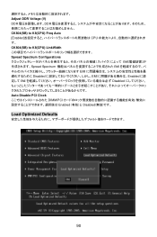
.... Load Optimized Defaults You can load the default values provided by EMI, set to Enabled for long-term purpose is used to auto disable the PCI slots. If select Limit, the memory speed will be based on SPDs. Adjust DDR Voltage (V) Adjusting the DDR voltage can introduce a temporary boost in clock speed which may cause a stability issue, so changing the DDR voltage for EMI reduction. CK804(SB) to K8(CPU) LinkWidth...
.... Load Optimized Defaults You can load the default values provided by EMI, set to Enabled for long-term purpose is used to auto disable the PCI slots. If select Limit, the memory speed will be based on SPDs. Adjust DDR Voltage (V) Adjusting the DDR voltage can introduce a temporary boost in clock speed which may cause a stability issue, so changing the DDR voltage for EMI reduction. CK804(SB) to K8(CPU) LinkWidth...

User Guide
Page 61
Out B:Mic-In JPW1 JWR1 JSP1 SFAN1 JCI1 Winbond W83627EHG PCI _E1 BIOS J1 ALC665 PCI _E2 PCI 1 PCI 2 JAUD1 PCI 3 55 DIMM1 DIMM2 BATT + JUSB1 JUSB2 JBAT1 FDD 1 JFP1 JFP2 简介 K9N4 Ultra系列 (MS-7310 v1.x) ATX主板. The K9N4 Ultra nForce 500 Ultra AMD® Socket-AM2 处理器, K9N4 Ultra 布局 Top : mouse Bottom: keyboard CFAN1 Top : Parallel Port Bottom: COM 1 IDE 1 SATA3 SATA1 SATA4 SATA2 USB ports Top: LAN jack Bottom: USB ports T:Line-In M:Line-
Out B:Mic-In JPW1 JWR1 JSP1 SFAN1 JCI1 Winbond W83627EHG PCI _E1 BIOS J1 ALC665 PCI _E2 PCI 1 PCI 2 JAUD1 PCI 3 55 DIMM1 DIMM2 BATT + JUSB1 JUSB2 JBAT1 FDD 1 JFP1 JFP2 简介 K9N4 Ultra系列 (MS-7310 v1.x) ATX主板. The K9N4 Ultra nForce 500 Ultra AMD® Socket-AM2 处理器, K9N4 Ultra 布局 Top : mouse Bottom: keyboard CFAN1 Top : Parallel Port Bottom: COM 1 IDE 1 SATA3 SATA1 SATA4 SATA2 USB ports Top: LAN jack Bottom: USB ports T:Line-In M:Line-

User Guide
Page 71
Save & Exit Setup CMOS Setup 程序. Exit Without Saving CMOS Setup 程序. Load Optimized Defaults BIOS 值. Current CPU Clock(当前 CPU 时钟) CPU Current FSB Multiplier CPU Vcore(CPU CPU Cool'n'Quiet AMD CPU CPU CPU Frequency Configuration(CPU CPU Memory CLK Memclock mode Auto SPD Limit Manual SPD 65 BIOS Setting Password(BIOS BIOS 的密码.
Save & Exit Setup CMOS Setup 程序. Exit Without Saving CMOS Setup 程序. Load Optimized Defaults BIOS 值. Current CPU Clock(当前 CPU 时钟) CPU Current FSB Multiplier CPU Vcore(CPU CPU Cool'n'Quiet AMD CPU CPU CPU Frequency Configuration(CPU CPU Memory CLK Memclock mode Auto SPD Limit Manual SPD 65 BIOS Setting Password(BIOS BIOS 的密码.

User Guide
Page 73
The K9N4 Ultra nForce 500 Ultra AMD® Socket-AM2 處理器, K9N4 Ultra 設定 Top : mouse Bottom: keyboard CFAN1 Top : Parallel Port Bottom: COM 1 IDE 1 SATA3 SATA1 SATA4 SATA2 USB ports Top: LAN jack Bottom: USB ports T:Line-In M:Line- Out B:Mic-In JPW1 JWR1 JSP1 SFAN1 JCI1 Winbond W83627EHG PCI _E1 BIOS J1 ALC665 JAUD1 PCI _E2 PCI 1 PCI 2 PCI 3 67 DIMM1 DIMM2 BATT + JUSB1 JUSB2 JBAT1 FDD 1 JFP1 JFP2 簡介 K9N4 Ultra系列 (MS-7310 v1.x) ATX主機板.
The K9N4 Ultra nForce 500 Ultra AMD® Socket-AM2 處理器, K9N4 Ultra 設定 Top : mouse Bottom: keyboard CFAN1 Top : Parallel Port Bottom: COM 1 IDE 1 SATA3 SATA1 SATA4 SATA2 USB ports Top: LAN jack Bottom: USB ports T:Line-In M:Line- Out B:Mic-In JPW1 JWR1 JSP1 SFAN1 JCI1 Winbond W83627EHG PCI _E1 BIOS J1 ALC665 JAUD1 PCI _E2 PCI 1 PCI 2 PCI 3 67 DIMM1 DIMM2 BATT + JUSB1 JUSB2 JBAT1 FDD 1 JFP1 JFP2 簡介 K9N4 Ultra系列 (MS-7310 v1.x) ATX主機板.

User Guide
Page 83
Current CPU Clock(當前 CPU 時脈) CPU Current FSB Multiplier CPU Vcore(CPU CPU Cool'n'Quiet AMD CPU CPU CPU Frequency Configuration(CPU CPU Memory CLK Memclock mode Auto SPD Limit Manual SPD 77 Load Optimized Defaults BIOS 值. Save & Exit Setup CMOS Setup 程式. Exit Without Saving CMOS Setup 程式. BIOS Setting Password(BIOS BIOS 的密碼.
Current CPU Clock(當前 CPU 時脈) CPU Current FSB Multiplier CPU Vcore(CPU CPU Cool'n'Quiet AMD CPU CPU CPU Frequency Configuration(CPU CPU Memory CLK Memclock mode Auto SPD Limit Manual SPD 77 Load Optimized Defaults BIOS 值. Save & Exit Setup CMOS Setup 程式. Exit Without Saving CMOS Setup 程式. BIOS Setting Password(BIOS BIOS 的密碼.

User Guide
Page 85
Out B:Mic-In JPW1 JWR1 JSP1 SFAN1 JCI1 Winbond W83627EHG PCI _E1 BIOS J1 ALC665 PCI _E2 PCI 1 PCI 2 JAUD1 PCI 3 79 DIMM1 DIMM2 BATT + JUSB1 JUSB2 JBAT1 FDD 1 JFP1 JFP2 K9N4 Ultra (MS-7310 v1.x) ATX K9N4 Ultra Force 500 Ultra AMD® Socket-AM2 K9N4 Ultra Top : mouse Bottom: keyboard CFAN1 Top : Parallel Port Bottom: COM 1 IDE 1 SATA3 SATA1 SATA4 SATA2 USB ports Top: LAN jack Bottom: USB ports T:Line-In M:Line-
Out B:Mic-In JPW1 JWR1 JSP1 SFAN1 JCI1 Winbond W83627EHG PCI _E1 BIOS J1 ALC665 PCI _E2 PCI 1 PCI 2 JAUD1 PCI 3 79 DIMM1 DIMM2 BATT + JUSB1 JUSB2 JBAT1 FDD 1 JFP1 JFP2 K9N4 Ultra (MS-7310 v1.x) ATX K9N4 Ultra Force 500 Ultra AMD® Socket-AM2 K9N4 Ultra Top : mouse Bottom: keyboard CFAN1 Top : Parallel Port Bottom: COM 1 IDE 1 SATA3 SATA1 SATA4 SATA2 USB ports Top: LAN jack Bottom: USB ports T:Line-In M:Line-

User Guide
Page 95
Load Optimized Defaults BIOS BIOS Setting Password Save & Exit Setup CMOS Exit Without Saving CMOS Frequency/Voltage Current CPU Clock CPU Current FSB Multiplier CPU Vcore CPU Cool'n'Quiet Cpp;'Quiet CPU Frequency Configuration CPU Memory CLK Memclock Mode Auto s Limit Manual」を 89
Load Optimized Defaults BIOS BIOS Setting Password Save & Exit Setup CMOS Exit Without Saving CMOS Frequency/Voltage Current CPU Clock CPU Current FSB Multiplier CPU Vcore CPU Cool'n'Quiet Cpp;'Quiet CPU Frequency Configuration CPU Memory CLK Memclock Mode Auto s Limit Manual」を 89
User Guide
Page 96
Adjust DDR Voltage (V) DDR DDR CK804(SB) to K8(CPU) Freq Auto [Enabled CPU CK804(SB) to K8(CPU) LinkWidth Spread Spectrum Configurations EMI Spread Spectrum EMI EMI Disabled EMI Enabled EMI Disabled Auto Disable PCI Clock DIMM/PCI Enabled Disabled Load Optimized Defaults 90
Adjust DDR Voltage (V) DDR DDR CK804(SB) to K8(CPU) Freq Auto [Enabled CPU CK804(SB) to K8(CPU) LinkWidth Spread Spectrum Configurations EMI Spread Spectrum EMI EMI Disabled EMI Enabled EMI Disabled Auto Disable PCI Clock DIMM/PCI Enabled Disabled Load Optimized Defaults 90


