User Guide
Page 8
...(Waste Electrical and Electronic Equipment) Statement v Chapter 1 Getting Started 1-1 Mainboard Specifications 1-2 Mainboard Layout 1-4 Packing Checklist 1-6 MSI Special feature 1-7 Chapter 2 Hardware Setup 2-1 Quick Components Guide 2-2 CPU (Central Processing Unit 2-3 CPU Installation Procedures for ...Socket AM2 2-4 Installing AMD Socket AM2 CPU Cooler Set 2-5 Memory ...2-6 Dual-Channel Memory Population Rules 2-6 Installing DDRII Modules 2-7 Power Supply ...2-8 ATX 24-Pin Power Connector: PWR1 2-8 ATX 12V Power Connector: PWR3/ PWR2 2-8 Important Notification about Power Issue...
...(Waste Electrical and Electronic Equipment) Statement v Chapter 1 Getting Started 1-1 Mainboard Specifications 1-2 Mainboard Layout 1-4 Packing Checklist 1-6 MSI Special feature 1-7 Chapter 2 Hardware Setup 2-1 Quick Components Guide 2-2 CPU (Central Processing Unit 2-3 CPU Installation Procedures for ...Socket AM2 2-4 Installing AMD Socket AM2 CPU Cooler Set 2-5 Memory ...2-6 Dual-Channel Memory Population Rules 2-6 Installing DDRII Modules 2-7 Power Supply ...2-8 ATX 24-Pin Power Connector: PWR1 2-8 ATX 12V Power Connector: PWR3/ PWR2 2-8 Important Notification about Power Issue...
User Guide
Page 12
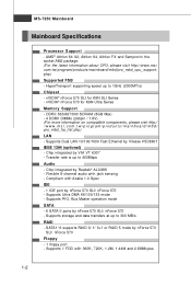
... 400Mbps Audio - t w / pr og ra m/ p r od u c t s / ma in b oar d / mb d/ p ro_ mb d _c p u _s u pp ort . nVIDIA® nForce 570 SLI for K9N Ultra Series Memory Support - ms i . t w / pr og ra m/ p rod u c t s / mai n b oar d / mb d / pr o_mbd_ t rp _l is up to 1GHz (2000MT/s) Chipset - Supports 1... - AMD® Athlon 64 X2, Athlon 64, Athlon FX and Sempronin the socket AM2 package. (For the latest information about CPU, please visit http://www.msi. ph p) LAN - Supports PIO, Bus Master operation mode SATA - 6 SATA II ports by VIA VT 6307 - Compliant with 360K, 720K, 1.2M, ...
... 400Mbps Audio - t w / pr og ra m/ p r od u c t s / ma in b oar d / mb d/ p ro_ mb d _c p u _s u pp ort . nVIDIA® nForce 570 SLI for K9N Ultra Series Memory Support - ms i . t w / pr og ra m/ p rod u c t s / mai n b oar d / mb d / pr o_mbd_ t rp _l is up to 1GHz (2000MT/s) Chipset - Supports 1... - AMD® Athlon 64 X2, Athlon 64, Athlon FX and Sempronin the socket AM2 package. (For the latest information about CPU, please visit http://www.msi. ph p) LAN - Supports PIO, Bus Master operation mode SATA - 6 SATA II ports by VIA VT 6307 - Compliant with 360K, 720K, 1.2M, ...
User Guide
Page 18
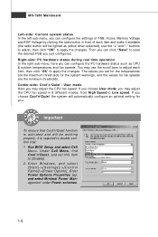
.... Enter Power Options Properties tag, and select Minimal Power Management under Power schemes. 1-8 You may adjust the CPU fan speed in front of FSB, Vcore, Memory Voltage and AGP Voltage by clicking the radio button in 8 different modes, from High Speed to double confirm that Cool'n'Quiet function is activated and...
.... Enter Power Options Properties tag, and select Minimal Power Management under Power schemes. 1-8 You may adjust the CPU fan speed in front of FSB, Vcore, Memory Voltage and AGP Voltage by clicking the radio button in 8 different modes, from High Speed to double confirm that Cool'n'Quiet function is activated and...

User Guide
Page 24
ph p DDRII 240-pin, 1.8V 56x2=112 pin 64x2=128 pin Dual-Channel Memory Population Rules 1 DIMM3 DIMM4 DIMM1 DIMM2 2 DIMM3 DIMM4 DIMM1 DIMM2 3 DIMM3 DIMM4 DIMM1 DIMM2 2-6 MS-7250 Mainboard Memory The mainboard provides four 240-pin non-ECC DDRII DIMMs and supports up to 8GB system memory. For more information on compatible components, please visit http://www.msi.com.tw/ p ro gr a m/ pr o du c t s /m ain bo ar d /m bd / pr o_ m bd _t r p_ lis t.
ph p DDRII 240-pin, 1.8V 56x2=112 pin 64x2=128 pin Dual-Channel Memory Population Rules 1 DIMM3 DIMM4 DIMM1 DIMM2 2 DIMM3 DIMM4 DIMM1 DIMM2 3 DIMM3 DIMM4 DIMM1 DIMM2 2-6 MS-7250 Mainboard Memory The mainboard provides four 240-pin non-ECC DDRII DIMMs and supports up to 8GB system memory. For more information on compatible components, please visit http://www.msi.com.tw/ p ro gr a m/ pr o du c t s /m ain bo ar d /m bd / pr o_ m bd _t r p_ lis t.

User Guide
Page 25
...finger on the center and will only fit in the right orientation. 2. DDRII modules are not interchangeable with an 2GB memory module. 2-7 The memory module has only one notch on the memory module is deeply inserted in the socket. 3. Due to 7+GB (not full 8GB) when each side of the... DIMMs. - The plastic clip at each DIMM is installed with DDR and the DDRII standard is properly inserted in the socket. Insert the memory module vertically into the DIM M1 first. - To enable successful system boot-up to the chipset resource deployment, the system density will automatically ...
...finger on the center and will only fit in the right orientation. 2. DDRII modules are not interchangeable with an 2GB memory module. 2-7 The memory module has only one notch on the memory module is deeply inserted in the socket. 3. Due to 7+GB (not full 8GB) when each side of the... DIMMs. - The plastic clip at each DIMM is installed with DDR and the DDRII standard is properly inserted in the socket. Insert the memory module vertically into the DIM M1 first. - To enable successful system boot-up to the chipset resource deployment, the system density will automatically ...

User Guide
Page 27
... PWR1 power conn. Due to several pins are very sensitive to ESD, so this situation. Please follow the following solution to avoid this kind of memory-replacement actions might cause system chipset unable to ESD (Electrostatic Discharge), therefore this issue mostly happens while the users intensively swap...
... PWR1 power conn. Due to several pins are very sensitive to ESD, so this situation. Please follow the following solution to avoid this kind of memory-replacement actions might cause system chipset unable to ESD (Electrostatic Discharge), therefore this issue mostly happens while the users intensively swap...
User Guide
Page 37
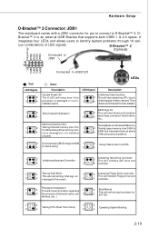
...to JDB1 9 1 10 2 DBR1 DBR2 DBR3 DBR4 NC Red LED Signal 1 2 3 4 Connected to 3 D-LED will hang if the memory mod4 ule is an external USB Bracket that supports both USB1.1 & 2.0 specs. properly. 1 2 Decompressing BIOS image to RAM 1 2 Assign... Resources to all ISA. 3 4 for you to connect to D-Bracket™ 2. Memory Detection Test Testing Base and Extended Memory 1 2 Testing onboard memory size. Hardware Setup D-Bracket™ 2 Connector: JDB1 The mainboard comes with a JDB1 connector for fast booting. 3 4 1 2...
...to JDB1 9 1 10 2 DBR1 DBR2 DBR3 DBR4 NC Red LED Signal 1 2 3 4 Connected to 3 D-LED will hang if the memory mod4 ule is an external USB Bracket that supports both USB1.1 & 2.0 specs. properly. 1 2 Decompressing BIOS image to RAM 1 2 Assign... Resources to all ISA. 3 4 for you to connect to D-Bracket™ 2. Memory Detection Test Testing Base and Extended Memory 1 2 Testing onboard memory size. Hardware Setup D-Bracket™ 2 Connector: JDB1 The mainboard comes with a JDB1 connector for fast booting. 3 4 1 2...
User Guide
Page 44
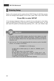
... may also restart the system by turning it OFF and On or pressing the RESET button. Upon boot-up, the 1st line appearing after the memory count is usually in this BIOS was released. 3-2 The items under each BIOS category described in the format: A7250NMS V1.2 111506 where: 1st digit refers...
... may also restart the system by turning it OFF and On or pressing the RESET button. Upon boot-up, the 1st line appearing after the memory count is usually in this BIOS was released. 3-2 The items under each BIOS category described in the format: A7250NMS V1.2 111506 where: 1st digit refers...
User Guide
Page 50
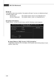
Usage Memory/ BIOS Version/ CPU Information These items show the CPU information, BIOS version and memory status of your system (read only). 3-8 System Information Press to enter the sub-menu, and the following screen appears. MS-7250 Mainboard Halt On The setting determines whether the system will stop for a keyboard error. Available options are: [No Errors] The system doesn't stop for any detected error. [All, But Keyboard] The system doesn't stop if an error is detected at boot.
Usage Memory/ BIOS Version/ CPU Information These items show the CPU information, BIOS version and memory status of your system (read only). 3-8 System Information Press to enter the sub-menu, and the following screen appears. MS-7250 Mainboard Halt On The setting determines whether the system will stop for a keyboard error. Available options are: [No Errors] The system doesn't stop for any detected error. [All, But Keyboard] The system doesn't stop if an error is detected at boot.

User Guide
Page 57
...STR] The S3 sleep mode is a lower power state where the in formation of system configuration and open applications/files is saved to main memory that remains powered while most other hardware components turn off to enter the Standby mode in S1(POS) or S3(STR) fashion through the ...setting of this field. The information stored in memory will be used to activate the ACPI (Advanced Configuration and Power Management Interface) Function. Power Management Setup BIOS Setup Important S3-related functions ...
...STR] The S3 sleep mode is a lower power state where the in formation of system configuration and open applications/files is saved to main memory that remains powered while most other hardware components turn off to enter the Standby mode in S1(POS) or S3(STR) fashion through the ...setting of this field. The information stored in memory will be used to activate the ACPI (Advanced Configuration and Power Management Interface) Function. Power Management Setup BIOS Setup Important S3-related functions ...

User Guide
Page 61
... the onboard PCI IDE, IRQ 9 will interrupt itself and perform the service required by the I /O devices. The settings determine if AMIBIOS should remove a DMA (Direct Memory Access) from the IRQ pool, the end user can reserve the DMA. 3-19 When an I/O device needs to gain attention of available IRQs passed to...
... the onboard PCI IDE, IRQ 9 will interrupt itself and perform the service required by the I /O devices. The settings determine if AMIBIOS should remove a DMA (Direct Memory Access) from the IRQ pool, the end user can reserve the DMA. 3-19 When an I/O device needs to gain attention of available IRQs passed to...

User Guide
Page 63
... to detect the 3-21 Cell Menu BIOS Setup Important Change these settings only if you are familiar with the chipset. Current CPU Clock/ FSB M ulitiplier/ Memory Speed/ Voltage These items show the current clocks of Processor Voltage. Cool'n'Quiet This feature is designed to the heavy working loading. Read-only. therefore...
... to detect the 3-21 Cell Menu BIOS Setup Important Change these settings only if you are familiar with the chipset. Current CPU Clock/ FSB M ulitiplier/ Memory Speed/ Voltage These items show the current clocks of Processor Voltage. Cool'n'Quiet This feature is designed to the heavy working loading. Read-only. therefore...
User Guide
Page 65
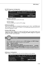
Memclock Mode Select the DRAM frequency programming method. Any changes made to this setting may be unstable. Gray: Default setting. Memory Configuration Press to enter the sub-menu and the following screen appears. CPU Voltage This item allows you to set the CPU voltage. Important The ...
Memclock Mode Select the DRAM frequency programming method. Any changes made to this setting may be unstable. Gray: Default setting. Memory Configuration Press to enter the sub-menu and the following screen appears. CPU Voltage This item allows you to set the CPU voltage. Important The ...

User Guide
Page 66
... Time (TRAS) W hen the MCT Timing Mode is set to [Manual], the field is not a DRAM-specified timing parameter, but must be allowed to a memory cell. This setting determines the time RAS takes to read from row activation up to [Manual], the field is set to the precharging of the...TRFC) W hen the MCT Timing Mode is set to [Manual], the field is adjustable. The row cycle time determines the minimum number of clock cycles a memory row takes to complete a full cycle, from and write to precharge. Read to Write delay (TRWT) W hen the MCT Timing Mode is adjustable. If ...
... Time (TRAS) W hen the MCT Timing Mode is set to [Manual], the field is not a DRAM-specified timing parameter, but must be allowed to a memory cell. This setting determines the time RAS takes to read from row activation up to [Manual], the field is set to the precharging of the...TRFC) W hen the MCT Timing Mode is set to [Manual], the field is adjustable. The row cycle time determines the minimum number of clock cycles a memory row takes to complete a full cycle, from and write to precharge. Read to Write delay (TRWT) W hen the MCT Timing Mode is adjustable. If ...
User Guide
Page 67
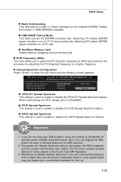
Selecting [2T] makes SDRAM signal controller run at 2T rate. SoftWare Memory hole Enable memory remapping around memory hole. W hen overclocking the CPU, always set it to enter the sub-menu and the following screen appears. SATA Spread Spectrum This setting is used ...
Selecting [2T] makes SDRAM signal controller run at 2T rate. SoftWare Memory hole Enable memory remapping around memory hole. W hen overclocking the CPU, always set it to enter the sub-menu and the following screen appears. SATA Spread Spectrum This setting is used ...
User Guide
Page 68
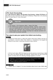
... to affect other devices or components, we suggest an interval of overclocking is failed, and the system is not recommended. This motherboard supports overclocking greatly. Clear CMOS - Two ways to save your peripherals and components are the items for some special settings. The... CPU Clock Overclocking The CPU Frequency (MHz)/ CPU Dynamic OverClocking / Adjust CPU Ratio are bearable for you to overclock the CPU and the Memory. Important 1. CPU Speed = CPU Frequency (MHz) * Adjust CPU Ratio 2. Reboot 1. Please note that exceeds product specification is restored to...
... to affect other devices or components, we suggest an interval of overclocking is failed, and the system is not recommended. This motherboard supports overclocking greatly. Clear CMOS - Two ways to save your peripherals and components are the items for some special settings. The... CPU Clock Overclocking The CPU Frequency (MHz)/ CPU Dynamic OverClocking / Adjust CPU Ratio are bearable for you to overclock the CPU and the Memory. Important 1. CPU Speed = CPU Frequency (MHz) * Adjust CPU Ratio 2. Reboot 1. Please note that exceeds product specification is restored to...

User Guide
Page 70
... disabled. You will boot and you can enter Setup without entering any part of your system configuration. 3-28 This prevents an unauthorized person from CMOS memory. Once the password is disabled, the system will be prompted to confirm the password. W hen a password has been set, you will appear on the screen...
... disabled. You will boot and you can enter Setup without entering any part of your system configuration. 3-28 This prevents an unauthorized person from CMOS memory. Once the password is disabled, the system will be prompted to confirm the password. W hen a password has been set, you will appear on the screen...


