User Guide
Page 8
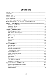
Getting Started 1-1 Mainboard Specifications 1-2 Mainboard Layout 1-4 Packing Checklist 1-5 Chapter 2. Hardware Setup 2-1 Quick Components Guide 2-2 CPU (Central Processing Unit 2-3 Memory ...2-6 Power Supply ...2-8 Back Panel ...2-9 Connectors ...2-11 Jumpers ...2-18 Slots ...2-19 Chapter 3 ...
Getting Started 1-1 Mainboard Specifications 1-2 Mainboard Layout 1-4 Packing Checklist 1-5 Chapter 2. Hardware Setup 2-1 Quick Components Guide 2-2 CPU (Central Processing Unit 2-3 Memory ...2-6 Power Supply ...2-8 Back Panel ...2-9 Connectors ...2-11 Jumpers ...2-18 Slots ...2-19 Chapter 3 ...
User Guide
Page 10
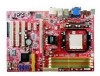
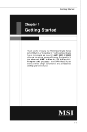
Getting Started Chapter 1 Getting Started Thank you for optimal system efficiency. Designed to fit the advanced AM D® Athlon 64 X2/ Athlon 64 / Sempron AM2 processor, the K9AG Neo2-Digital Series deliver a high performance and professional desktop platform solution. 1-1 The K9AG Neo2-Digital Series mainboards are based on AMD® 690G & SB600 chipsets for choosing the K9AG Neo2-Digital Series (MS-7368v1.X) ATX mainboard.
Getting Started Chapter 1 Getting Started Thank you for optimal system efficiency. Designed to fit the advanced AM D® Athlon 64 X2/ Athlon 64 / Sempron AM2 processor, the K9AG Neo2-Digital Series deliver a high performance and professional desktop platform solution. 1-1 The K9AG Neo2-Digital Series mainboards are based on AMD® 690G & SB600 chipsets for choosing the K9AG Neo2-Digital Series (MS-7368v1.X) ATX mainboard.
User Guide
Page 11
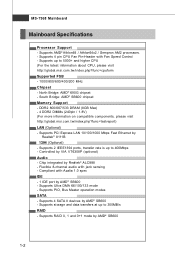
... AMD® SB600 - Supports 4 SATA II devices by Realtek® 8111B 1394 (Optional) - Supports 4 pin CPU Fan Pin-Header with jack sensing - m si. MS-7368 Mainboard Mainboard Specifications Processor Support - m si. Supports AMD® Athlon64 / Athlon64x2 / Sempron AM2 processors. - t w / index.
... AMD® SB600 - Supports 4 SATA II devices by Realtek® 8111B 1394 (Optional) - Supports 4 pin CPU Fan Pin-Header with jack sensing - m si. MS-7368 Mainboard Mainboard Specifications Processor Support - m si. Supports AMD® Athlon64 / Athlon64x2 / Sempron AM2 processors. - t w / index.

User Guide
Page 13
MS-7368 Mainboard Mainboard Layout Top: M ou se Bottom : Key board HDMI Port J1 J2 To p: VGA Port Bottom : DVI Port CPUFAN 1 To p: IEEE13 94 Port (optional) Bo ttom : ... JSPD1 PCI3 JCOM 1 SYSFAN2 BATT + JBAT1 AMD SB600 SATA1 IDE1 SATA4 SATA2 SATA3 FDD1 VIA VT6308P (optional) J 13 94_1 (optional) JUSB2 JUSB3 JUSB1 JFP 2 JFP 1 K9AG Neo2-Digital Series (MS-7368 v1.X) ATX Mainboard 1-4
MS-7368 Mainboard Mainboard Layout Top: M ou se Bottom : Key board HDMI Port J1 J2 To p: VGA Port Bottom : DVI Port CPUFAN 1 To p: IEEE13 94 Port (optional) Bo ttom : ... JSPD1 PCI3 JCOM 1 SYSFAN2 BATT + JBAT1 AMD SB600 SATA1 IDE1 SATA4 SATA2 SATA3 FDD1 VIA VT6308P (optional) J 13 94_1 (optional) JUSB2 JUSB3 JUSB1 JFP 2 JFP 1 K9AG Neo2-Digital Series (MS-7368 v1.X) ATX Mainboard 1-4

User Guide
Page 18
... a CPU socket called Socket AM2 (940-pin) for easy CPU installation. For the latest information about CPU, please visit http://global.msi.com.tw/index.php?func=cpuform Important 1. W hen you are installing the CPU, make sure the cooling fan can work properly to ... the CPU and the heatsink to prevent overheating. While replacing the CPU, always turn off the ATX power supply or unplug the power supply's power cord from overheating. 2. Hardware Setup CPU (Central Processing Unit) The mainboard supports AMD® Athlon64 / Athlon64x2 / Sempron AM2 processors. Always make sure the CPU has ...
... a CPU socket called Socket AM2 (940-pin) for easy CPU installation. For the latest information about CPU, please visit http://global.msi.com.tw/index.php?func=cpuform Important 1. W hen you are installing the CPU, make sure the cooling fan can work properly to ... the CPU and the heatsink to prevent overheating. While replacing the CPU, always turn off the ATX power supply or unplug the power supply's power cord from overheating. 2. Hardware Setup CPU (Central Processing Unit) The mainboard supports AMD® Athlon64 / Athlon64x2 / Sempron AM2 processors. Always make sure the CPU has ...

User Guide
Page 19
... Plate Open Lever 90 degree 3. Look for Socket AM2 1. The CPU can not be completely embedded into the socket and close the lever with your mainboard. If the CPU is correctly installed, the pins should point as shown in the correct orientation. Press the CPU down firmly into the socket and... tightly on top of the CPU. As the CPU is likely to move while the lever is being closed, always close the lever. MS-7368 Mainboard CPU Installation Procedures for the gold arrow of the CPU to make sure the CPU is properly and completely embedded into the socket. 2-4 Pull the...
... Plate Open Lever 90 degree 3. Look for Socket AM2 1. The CPU can not be completely embedded into the socket and close the lever with your mainboard. If the CPU is correctly installed, the pins should point as shown in the correct orientation. Press the CPU down firmly into the socket and... tightly on top of the CPU. As the CPU is likely to move while the lever is being closed, always close the lever. MS-7368 Mainboard CPU Installation Procedures for the gold arrow of the CPU to make sure the CPU is properly and completely embedded into the socket. 2-4 Pull the...

User Guide
Page 20
... to purchase and install them before turning on the computer. Then press down the lever. 4. Attach the CPU Fan cable to prevent overheating. Important Mainboard photos shown in this section are installing the CPU, make sure the CPU has a heat sink and a cooling fan attached on the top to ...the CPU fan connector on the model you purchase. 1. The appearance of the clip to keep an eye on your mainboard may vary depending on the mainboard. * While disconnecting the Safety Hook from the fixed bolt, the fixed lever will spring back instantly. 2-5 Locate the Fix Lever and...
... to purchase and install them before turning on the computer. Then press down the lever. 4. Attach the CPU Fan cable to prevent overheating. Important Mainboard photos shown in this section are installing the CPU, make sure the CPU has a heat sink and a cooling fan attached on the top to ...the CPU fan connector on the model you purchase. 1. The appearance of the clip to keep an eye on your mainboard may vary depending on the mainboard. * While disconnecting the Safety Hook from the fixed bolt, the fixed lever will spring back instantly. 2-5 Locate the Fix Lever and...
User Guide
Page 21
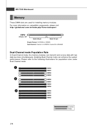
Please refer to the following illustrations for installing memory modules. For more information on compatible components, please visit http://global.msi.com.tw/index.php?func=testreport DDR2 240-pin, 1.8V 64x2=128 pin 56x2=112 pin Single-Channel: All DIMMs in GREEN ... the system performance. Channel B in GREEN; Enabling Dual-Channel mode can transmit and receive data with two data bus lines simultaneously. MS-7368 Mainboard Memory These DIMM slots are used for population rules under Dual-Channel mode. 1 DIMM2 DIMM1 DIMM4 DIMM3 2 DIMM2 DIMM1 DIMM4 DIMM3 3 DIMM2 ...
Please refer to the following illustrations for installing memory modules. For more information on compatible components, please visit http://global.msi.com.tw/index.php?func=testreport DDR2 240-pin, 1.8V 64x2=128 pin 56x2=112 pin Single-Channel: All DIMMs in GREEN ... the system performance. Channel B in GREEN; Enabling Dual-Channel mode can transmit and receive data with two data bus lines simultaneously. MS-7368 Mainboard Memory These DIMM slots are used for population rules under Dual-Channel mode. 1 DIMM2 DIMM1 DIMM4 DIMM3 2 DIMM2 DIMM1 DIMM4 DIMM3 3 DIMM2 ...
User Guide
Page 23
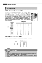
...-pin power supply. Maker sure that all the connectors are aligned. There is inserted in the proper orientation and the pins are connected to proper ATX power supplies to the image at the right hand). JPW1 4 2 3 1 JPW1 Pin Definition PIN SIGNAL 1 GND 2 GND 3 12V 4 12V...12V 12 +3.3V 23 +5V 24 GND pin 13 pin 12 ATX 12V Power Connector: JPW1 This 12V power connector JPW 1 is highly recommended for system stability. 2-8 Power supply of the mainboard. 2. MS-7368 Mainboard Power Supply ATX 24-Pin Power Connector: ATX1 This connector allows you to the...
...-pin power supply. Maker sure that all the connectors are aligned. There is inserted in the proper orientation and the pins are connected to proper ATX power supplies to the image at the right hand). JPW1 4 2 3 1 JPW1 Pin Definition PIN SIGNAL 1 GND 2 GND 3 12V 4 12V...12V 12 +3.3V 23 +5V 24 GND pin 13 pin 12 ATX 12V Power Connector: JPW1 This 12V power connector JPW 1 is highly recommended for system stability. 2-8 Power supply of the mainboard. 2. MS-7368 Mainboard Power Supply ATX 24-Pin Power Connector: ATX1 This connector allows you to the...

User Guide
Page 25
... color of the audio jacks for attaching USB devices such as keyboard, mouse, or other audio devices. Line-In (Blue) - RS-Out (Black) - MS-7368 Mainboard USB Port The USB (Universal Serial Bus) port is for different audio sound effects. Line-Out (Green) - SS-Out (Gray) - Line Out, is a connector for...
... color of the audio jacks for attaching USB devices such as keyboard, mouse, or other audio devices. Line-In (Blue) - RS-Out (Black) - MS-7368 Mainboard USB Port The USB (Universal Serial Bus) port is for different audio sound effects. Line-Out (Green) - SS-Out (Gray) - Line Out, is a connector for...

User Guide
Page 27
... the BIOS utility and clear the record. 1 CINTRU 2 GND JCI1 CD-In Connector: JCD1 This connector is a high-speed Serial ATA interface port. MS-7368 Mainboard Serial ATA Connector: SATA1/ SATA2/ SATA3/ SATA4 This connector is provided for external audio input. 2-12 L GND R JCD1 SATA1 SATA2 SATA3 SATA4 Important Please do...
... the BIOS utility and clear the record. 1 CINTRU 2 GND JCI1 CD-In Connector: JCD1 This connector is a high-speed Serial ATA interface port. MS-7368 Mainboard Serial ATA Connector: SATA1/ SATA2/ SATA3/ SATA4 This connector is provided for external audio input. 2-12 L GND R JCD1 SATA1 SATA2 SATA3 SATA4 Important Please do...

User Guide
Page 28
... 8 NC 9 LINE out_L 10 LINEout_JD 2 1 10 9 JAUD1 HD Audio Pin Definition DESCRIPTION Microphone - Fan/heatsink with Intel® Front Panel I/O Connectivity Design Guide. If the mainboard has a System Hardware Monitor chipset on-board, you to connect the front panel audio and is connected to the +12V; Please refer to the recommended...
... 8 NC 9 LINE out_L 10 LINEout_JD 2 1 10 9 JAUD1 HD Audio Pin Definition DESCRIPTION Microphone - Fan/heatsink with Intel® Front Panel I/O Connectivity Design Guide. If the mainboard has a System Hardware Monitor chipset on-board, you to connect the front panel audio and is connected to the +12V; Please refer to the recommended...

User Guide
Page 29
Do not use. The JFP1 is compliant with Intel® Front Panel I/O Connectivity Design Guide. MS-7368 Mainboard Front Panel Connectors: JFP1, JFP2 These connectors are for electrical connection to GND Reserved. Power LED JFP2 7 1 8 2 -+ + - Speaker Reset HDD Switch LED +- -+ JFP1 9 10 1 2 -+ Power ...
Do not use. The JFP1 is compliant with Intel® Front Panel I/O Connectivity Design Guide. MS-7368 Mainboard Front Panel Connectors: JFP1, JFP2 These connectors are for electrical connection to GND Reserved. Power LED JFP2 7 1 8 2 -+ + - Speaker Reset HDD Switch LED +- -+ JFP1 9 10 1 2 -+ Power ...

User Guide
Page 31
... Receive Data Serial Out or Transmit Data Data Terminal Ready Ground Data Set Ready Request To Send Clear To Send Ring Indicate 2-16 MS-7368 Mainboard IEEE1394 Connector: J1394_1(Optional) This connector allows you to connect the IEEE1394 device via an optional IEEE1394 bracket. 9 1 10 2 J1394_1 Pin Definition PIN SIGNAL PIN...
... Receive Data Serial Out or Transmit Data Data Terminal Ready Ground Data Set Ready Request To Send Clear To Send Ring Indicate 2-16 MS-7368 Mainboard IEEE1394 Connector: J1394_1(Optional) This connector allows you to connect the IEEE1394 device via an optional IEEE1394 bracket. 9 1 10 2 J1394_1 Pin Definition PIN SIGNAL PIN...

User Guide
Page 33
... CMOS by shorting 2-3 pin while the system is a CMOS RAM onboard that has a power supply from an external battery to 1-2 pin position. MS-7368 Mainboard Jumpers Clear CMOS Jumper: JBAT1 There is off. JBAT1 1 1 3 Keep Data 1 3 Clear Data Important You can automatically boot OS every time it will... damage the mainboard. it is on . C1 J1 A1 B1 Enable the DVI port. Disable the DVI port. Disable the HDMI port. C1 J2 A1 B1 2-18 ...
... CMOS by shorting 2-3 pin while the system is a CMOS RAM onboard that has a power supply from an external battery to 1-2 pin position. MS-7368 Mainboard Jumpers Clear CMOS Jumper: JBAT1 There is off. JBAT1 1 1 3 Keep Data 1 3 Clear Data Important You can automatically boot OS every time it will... damage the mainboard. it is on . C1 J1 A1 B1 Enable the DVI port. Disable the DVI port. Disable the HDMI port. C1 J2 A1 B1 2-18 ...
User Guide
Page 37
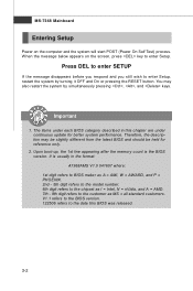
... to BIOS maker as A = AMI, W = AWARD, and P = PHOENIX. 2nd - 5th digit refers to the model number. 6th digit refers to the chipset as I = Intel, N = nVidia, and A = AMD. 7th - 8th digit refers to the customer as MS = all standard customers. MS-7368 Mainboard Entering Setup Power on the screen, press key to enter Setup. Press...
... to BIOS maker as A = AMI, W = AWARD, and P = PHOENIX. 2nd - 5th digit refers to the model number. 6th digit refers to the chipset as I = Intel, N = nVidia, and A = AMD. 7th - 8th digit refers to the customer as MS = all standard customers. MS-7368 Mainboard Entering Setup Power on the screen, press key to enter Setup. Press...
User Guide
Page 39
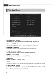
Power Management Setup Use this menu to load the default values set by the mainboard manufacturer specifically for power management. PNP/PCI Configurations This entry appears if your PC health status. H/W Monitor This entry shows your system supports PnP/PCI. ... menu to specify your settings for frequency/voltage control and overclocking. Cell Menu Use this menu to specify your settings for integrated peripherals. MS-7368 Mainboard The Main Menu Standard CMOS Features Use this menu to setup the items of the...
Power Management Setup Use this menu to load the default values set by the mainboard manufacturer specifically for power management. PNP/PCI Configurations This entry appears if your PC health status. H/W Monitor This entry shows your system supports PnP/PCI. ... menu to specify your settings for frequency/voltage control and overclocking. Cell Menu Use this menu to specify your settings for integrated peripherals. MS-7368 Mainboard The Main Menu Standard CMOS Features Use this menu to setup the items of the...
User Guide
Page 41
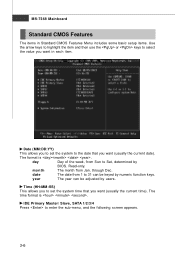
MS-7368 Mainboard Standard CMOS Features The items in each item. The time format is . The format is . Time (HH:MM :SS) This allows you to select the ...
MS-7368 Mainboard Standard CMOS Features The items in each item. The time format is . The format is . Time (HH:MM :SS) This allows you to select the ...

User Guide
Page 42
..., the logical block size in hard disk) mode. Important IDE Primary Master/ Slave, SATA 1/2/3/4 are appearing when you to the IDE/ SATA connector on the mainboard. Available options: [Disabled], [360 KB, 51/4"], [1.2 MB, 51/4"], [720 KB, 3 1/2"], [1.44 MB, 3 1/2"], [2.88 MB, 3 1/2"]. 3-7 DM A M ode This item allows you connect the HD devices to...
..., the logical block size in hard disk) mode. Important IDE Primary Master/ Slave, SATA 1/2/3/4 are appearing when you to the IDE/ SATA connector on the mainboard. Available options: [Disabled], [360 KB, 51/4"], [1.2 MB, 51/4"], [720 KB, 3 1/2"], [1.44 MB, 3 1/2"], [2.88 MB, 3 1/2"]. 3-7 DM A M ode This item allows you connect the HD devices to...

User Guide
Page 43
MS-7368 Mainboard System Information Press to enter the sub-menu, and the following screen appears. CPU Type, CPUID/MicroCode, CPU Frequency, BIOS Version, Physical Memory, Usage Memory, Cache Size This sub-menu shows the CPU information, BIOS version and memory status of your system (read only). 3-8
MS-7368 Mainboard System Information Press to enter the sub-menu, and the following screen appears. CPU Type, CPUID/MicroCode, CPU Frequency, BIOS Version, Physical Memory, Usage Memory, Cache Size This sub-menu shows the CPU information, BIOS version and memory status of your system (read only). 3-8


