User Guide
Page 9
Getting Started Getting Started Thank you for digital audio transmission. The K8T Neo2 is based on VIA® K8T800 Pro North Bridge & VT8237 South Bridge chipsets and provides eight USB 2.0 ports for high-speed data transmission, RealTek ALC850 chip for 7.1-channel audio output, and a SPDIF interface for purchasing K8T Neo2 (MS-6702E v1.X) ATX mainboard. Designed to fit the advanced AMD® Athlon 64 and Athlon 64 FX processors, the K8T Neo2 delivers a high performance and professional desktop platform solution. 1-1 Getting Started Chapter 1.
Getting Started Getting Started Thank you for digital audio transmission. The K8T Neo2 is based on VIA® K8T800 Pro North Bridge & VT8237 South Bridge chipsets and provides eight USB 2.0 ports for high-speed data transmission, RealTek ALC850 chip for 7.1-channel audio output, and a SPDIF interface for purchasing K8T Neo2 (MS-6702E v1.X) ATX mainboard. Designed to fit the advanced AMD® Athlon 64 and Athlon 64 FX processors, the K8T Neo2 delivers a high performance and professional desktop platform solution. 1-1 Getting Started Chapter 1.
User Guide
Page 10
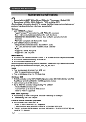
...h Supports a maximum memory size of 4GB h Supports Dual-channel DDR (For the updated supporting memory modules, please visit http://www.msi.com.tw/ program/products/mainboard/mbd/pro_mbd_trp_list.php.) Slots h One (Accelerated Graphics Port) AGP slot - Up to AMD Athlon 64 processor - 8 or 16 .../133 master mode PCI EIDE controller - RAID 0, RAID 1 supported IEEE 1394 (Optional) h Supports up to 2 serial ATA devices - MS-6702E ATX Mainboard Mainboard Specifications CPU h Supports 64-bit AMD® Athlon 64 and Athlon 64 FX processor (Socket 939) h Supports up to two SATA devices (such ...
...h Supports a maximum memory size of 4GB h Supports Dual-channel DDR (For the updated supporting memory modules, please visit http://www.msi.com.tw/ program/products/mainboard/mbd/pro_mbd_trp_list.php.) Slots h One (Accelerated Graphics Port) AGP slot - Up to AMD Athlon 64 processor - 8 or 16 .../133 master mode PCI EIDE controller - RAID 0, RAID 1 supported IEEE 1394 (Optional) h Supports up to 2 serial ATA devices - MS-6702E ATX Mainboard Mainboard Specifications CPU h Supports 64-bit AMD® Athlon 64 and Athlon 64 FX processor (Socket 939) h Supports up to two SATA devices (such ...
User Guide
Page 12
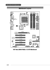
... FDD1 MS-6702E ATX Mainboard Mainboard Layout T: mouse B: keyboard CFAN1 DIMM 1 JCASE 1 Winbond W83627THF DIMM 3 DIMM 2 DIMM 4 (Optional) (Optional) JPW1 VIA K8T800 Pro S FA N 1 IDE 1 IDE 2 T: S P D I F O u t B:USB port T: LAN jack B: USB ... Slot 3 PCI Slot 4 PCI Slot 5 J1394_1 (Optional) SATA2 SATA1 IDE3 BATT + BIOS SER2 JUSB1 JUSB2 JLED1 JIR1 PROMISE (Optional) PDC20579 (Optional) (Optional) JFP2 JFP1 SER1 K8T Neo2 (MS-6702E) v1.X ATX Mainboard PWF_FAN1 PWF_ FAN2 JGS1 J B AT 1 1-4
... FDD1 MS-6702E ATX Mainboard Mainboard Layout T: mouse B: keyboard CFAN1 DIMM 1 JCASE 1 Winbond W83627THF DIMM 3 DIMM 2 DIMM 4 (Optional) (Optional) JPW1 VIA K8T800 Pro S FA N 1 IDE 1 IDE 2 T: S P D I F O u t B:USB port T: LAN jack B: USB ... Slot 3 PCI Slot 4 PCI Slot 5 J1394_1 (Optional) SATA2 SATA1 IDE3 BATT + BIOS SER2 JUSB1 JUSB2 JLED1 JIR1 PROMISE (Optional) PDC20579 (Optional) (Optional) JFP2 JFP1 SER1 K8T Neo2 (MS-6702E) v1.X ATX Mainboard PWF_FAN1 PWF_ FAN2 JGS1 J B AT 1 1-4
User Guide
Page 17
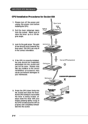
... note that any violation of the CPU to move while the lever is being closed, always close the lever. MS-6702E ATX Mainboard CPU Installation Procedures for the gold arrow. Please turn off the power and unplug the power cord before installing the CPU. 2. Gold arrow Gold arrow ...
... note that any violation of the CPU to move while the lever is being closed, always close the lever. MS-6702E ATX Mainboard CPU Installation Procedures for the gold arrow. Please turn off the power and unplug the power cord before installing the CPU. 2. Gold arrow Gold arrow ...
User Guide
Page 19
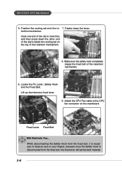
Locate the Fix Lever, Safety Hook and the Fixed Bolt. Hook one end of the clip to the CPU fan connector on the mainboard. Make sure the safety hook completely clasps the fixed bolt of the retention mechanism. 8. Safety Hook 9. tention mechanism. Lift up the intensive fixed ... the Safety Hook from the fixed bolt, it is disconnected from the fixed bolt, the fixed lever will spring back instantly. 2-6 MS-6702E ATX Mainboard 5. Position the cooling set on your fingers, because once the Safety Hook is necessary to keep an eye on the top of the retention mechanism...
Locate the Fix Lever, Safety Hook and the Fixed Bolt. Hook one end of the clip to the CPU fan connector on the mainboard. Make sure the safety hook completely clasps the fixed bolt of the retention mechanism. 8. Safety Hook 9. tention mechanism. Lift up the intensive fixed ... the Safety Hook from the fixed bolt, it is disconnected from the fixed bolt, the fixed lever will spring back instantly. 2-6 MS-6702E ATX Mainboard 5. Position the cooling set on your fingers, because once the Safety Hook is necessary to keep an eye on the top of the retention mechanism...

User Guide
Page 21
... NOT support the memory module installed with more than 18 pieces of this board works ONLY in the table above. - D - MS-6702E ATX Mainboard GREEN Slots PURPLE Slots DIMM1 (Ch A) Single channel Dual channel Dual channel 128MB~1GB DIMM2 (Ch A) 128MB~1GB 128MB~1GB 128MB~1GB DIMM3... (Ch B) 128MB~1GB DIMM4 (Ch B) System Density 128MB~1GB 128MB~1GB 256MB~2GB 128MB~1GB 512MB~4GB MSI Reminds You... - DDR combination of IC (integrated circuit). - tions listed in the 3 combina- Please select the identical memory modules to insert the memory...
... NOT support the memory module installed with more than 18 pieces of this board works ONLY in the table above. - D - MS-6702E ATX Mainboard GREEN Slots PURPLE Slots DIMM1 (Ch A) Single channel Dual channel Dual channel 128MB~1GB DIMM2 (Ch A) 128MB~1GB 128MB~1GB 128MB~1GB DIMM3... (Ch B) 128MB~1GB DIMM4 (Ch B) System Density 128MB~1GB 128MB~1GB 256MB~2GB 128MB~1GB 512MB~4GB MSI Reminds You... - DDR combination of IC (integrated circuit). - tions listed in the 3 combina- Please select the identical memory modules to insert the memory...
User Guide
Page 23
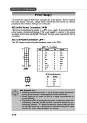
MS-6702E ATX Mainboard Power Supply The mainboard supports ATX power supply for system stability. 3. To connect to the ATX power supply, make sure that you to connect to 4 seconds or disconnect the power cable from the AC outlet, and then restart the system. 2-10 ATX 12V Power Connector: JPW1 ... 13 24 JPW1 JPW1 Pin Definition PIN SIGNAL 1 GND 2 GND 3 12V 4 12V MSI Reminds You... 1. Then push down and secured when CPU overheating occurred, so that all components are aligned. ATX 20-Pin Power Connector: JWR1 This connector allows you won't be caused. To release the...
MS-6702E ATX Mainboard Power Supply The mainboard supports ATX power supply for system stability. 3. To connect to the ATX power supply, make sure that you to connect to 4 seconds or disconnect the power cable from the AC outlet, and then restart the system. 2-10 ATX 12V Power Connector: JPW1 ... 13 24 JPW1 JPW1 Pin Definition PIN SIGNAL 1 GND 2 GND 3 12V 4 12V MSI Reminds You... 1. Then push down and secured when CPU overheating occurred, so that all components are aligned. ATX 20-Pin Power Connector: JWR1 This connector allows you won't be caused. To release the...

User Guide
Page 25
... USB-compatible devices. The standard IEEE1394 port connects to connect the IEEE1394 device with external power. MS-6702E ATX Mainboard Serial Port Connector The mainboard offers one 9-pin male DIN connector as keyboard, mouse or other PCs, and portable devices. 2-12 IEEE1394...Negative Data Channel 0 Positive Data Channel 0 Ground +5V Negative Data Channel 1 Positive Data Channel 1 Ground IEEE1394 Ports (Optional) The mainboard provides two IEEE 1394 ports in the rear I/O. The IEEE1394 high-speed serial bus components provide the enhanced PC connectivity for attaching USB devices...
... USB-compatible devices. The standard IEEE1394 port connects to connect the IEEE1394 device with external power. MS-6702E ATX Mainboard Serial Port Connector The mainboard offers one 9-pin male DIN connector as keyboard, mouse or other PCs, and portable devices. 2-12 IEEE1394...Negative Data Channel 0 Positive Data Channel 0 Ground +5V Negative Data Channel 1 Positive Data Channel 1 Ground IEEE1394 Ports (Optional) The mainboard provides two IEEE 1394 ports in the rear I/O. The IEEE1394 high-speed serial bus components provide the enhanced PC connectivity for attaching USB devices...

User Guide
Page 27
... / 5.1CH) 2-14 However, there is an advanced audio application provided by Realtek ALC850 to 4-/5.1-channel audio. Mic is a connector for Speakers or Headphones. MS-6702E ATX Mainboard Audio Port Connectors The left 3 audio jacks are for 2-channel mode for stereo speaker output: Line Out is a connector for microphones.
... / 5.1CH) 2-14 However, there is an advanced audio application provided by Realtek ALC850 to 4-/5.1-channel audio. Mic is a connector for Speakers or Headphones. MS-6702E ATX Mainboard Audio Port Connectors The left 3 audio jacks are for 2-channel mode for stereo speaker output: Line Out is a connector for microphones.
User Guide
Page 29
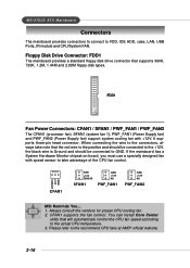
... SFAN1 GND +12V NC PWF_FAN1 GND +12V NC PWF_FAN2 MSI Reminds You... 1. Always consult the vendors for proper CPU cooling fan. 2. You can install Core Center utility that supports 360K, 720K, 1.2M, 1.44M and 2.88M floppy disk types. MS-6702E ATX Mainboard Connectors The mainboard provides connectors to connect to the recommend CPU fans...
... SFAN1 GND +12V NC PWF_FAN1 GND +12V NC PWF_FAN2 MSI Reminds You... 1. Always consult the vendors for proper CPU cooling fan. 2. You can install Core Center utility that supports 360K, 720K, 1.2M, 1.44M and 2.88M floppy disk types. MS-6702E ATX Mainboard Connectors The mainboard provides connectors to connect to the recommend CPU fans...

User Guide
Page 31
... software installation procedure. 71 SATA2 SATA1 Parallel ATA/Serial ATA RAID Connectors controlled by VT8237: SATA1/SATA2 The Southbridge of this mainboard is a 32-bit Enhanced PCI IDE and Ultra DMA 66/100/133 controller that provides PIO mode and DMA mode 0~5, Bus...ports. Each Serial ATA connector can connect to the hard disk devices 2-18 Both connectors are fully compliant with Serial ATA 1.0 specifications. MS-6702E ATX Mainboard Serial ATA/Serial ATA RAID Connectors con- SER1 & SER2 Pin Definition IDE3 1 7 SER2 SER1 Optional Serial ATA cable Pin Signal 1 GND ...
... software installation procedure. 71 SATA2 SATA1 Parallel ATA/Serial ATA RAID Connectors controlled by VT8237: SATA1/SATA2 The Southbridge of this mainboard is a 32-bit Enhanced PCI IDE and Ultra DMA 66/100/133 controller that provides PIO mode and DMA mode 0~5, Bus...ports. Each Serial ATA connector can connect to the hard disk devices 2-18 Both connectors are fully compliant with Serial ATA 1.0 specifications. MS-6702E ATX Mainboard Serial ATA/Serial ATA RAID Connectors con- SER1 & SER2 Pin Definition IDE3 1 7 SER2 SER1 Optional Serial ATA cable Pin Signal 1 GND ...

User Guide
Page 33
MS-6702E ATX Mainboard Front USB Connectors: JUSB1/JUSB2 The mainboard provides two standard USB 2.0 pin headers JUSB1 & JUSB2 . JUSB1 & JUSB2 Pin Definition 2 10 1 9 JUSB1, JUSB2 (USB 2.0) PIN SIGNAL 1 VCC 3 USB0- 5 USB0+ 7 GND PIN ... 2 VCC 4 USB1- 6 USB1+ 8 GND 9 Key (no pin) 10 SIGNAL TPAGround TPBCable power Ground 2-20 JCD1 GND R IEEE 1394 Connector: J1394_1 (Optional) The mainboard provides a 1394 pin header that allow you to connect IEEE 1394 port via an external IEEE1394 bracket (optional). 2 10 1 9 J1394_1 Pin Definition PIN SIGNAL PIN...
MS-6702E ATX Mainboard Front USB Connectors: JUSB1/JUSB2 The mainboard provides two standard USB 2.0 pin headers JUSB1 & JUSB2 . JUSB1 & JUSB2 Pin Definition 2 10 1 9 JUSB1, JUSB2 (USB 2.0) PIN SIGNAL 1 VCC 3 USB0- 5 USB0+ 7 GND PIN ... 2 VCC 4 USB1- 6 USB1+ 8 GND 9 Key (no pin) 10 SIGNAL TPAGround TPBCable power Ground 2-20 JCD1 GND R IEEE 1394 Connector: J1394_1 (Optional) The mainboard provides a 1394 pin header that allow you to connect IEEE 1394 port via an external IEEE1394 bracket (optional). 2 10 1 9 J1394_1 Pin Definition PIN SIGNAL PIN...
User Guide
Page 35
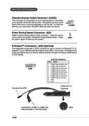
... be short. Press the switch again to have the system entered the Sleep/Suspend state. JGS1 D-Bracket™ 2 Connector: JLED (Optional) The mainboard comes with a JLED connector for red color) 9 Key 10 NC D-Bracket™ 2 (Optional) Connected to this status and show a warning ...message on the screen. DBracket™ 2 is connected to D-Bracket™ 2. Press the switch once to wake up the system. MS-6702E ATX Mainboard Chassis Intrusion Switch Connector: JCASE1 This connector is a USB Bracket that supports both USB1.1 & 2.0 spec. To clear the warning, you to connect...
... be short. Press the switch again to have the system entered the Sleep/Suspend state. JGS1 D-Bracket™ 2 Connector: JLED (Optional) The mainboard comes with a JLED connector for red color) 9 Key 10 NC D-Bracket™ 2 (Optional) Connected to this status and show a warning ...message on the screen. DBracket™ 2 is connected to D-Bracket™ 2. Press the switch once to wake up the system. MS-6702E ATX Mainboard Chassis Intrusion Switch Connector: JCASE1 This connector is a USB Bracket that supports both USB1.1 & 2.0 spec. To clear the warning, you to connect...
User Guide
Page 37
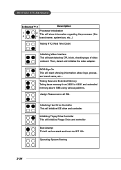
Then, detect and initialize the video adapter. Assign Resources to 640K and extended memory above 1MB using various patterns. MS-6702E ATX Mainboard D-Bracket™ 2 Description Processor Initialization 1 2 This will show information regarding the processor (like 3 4 brand name, system bus, etc...) Testing RTC (Real Time Clock) Initializing Video ...
Then, detect and initialize the video adapter. Assign Resources to 640K and extended memory above 1MB using various patterns. MS-6702E ATX Mainboard D-Bracket™ 2 Description Processor Initialization 1 2 This will show information regarding the processor (like 3 4 brand name, system bus, etc...) Testing RTC (Real Time Clock) Initializing Video ...
User Guide
Page 39
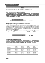
... C# Order 3 INT C# INT D# INT A# INT B# INT D# Order 4 INT D# INT A# INT B# INT C# INT A# 2-26 PCI Slots PCI Interrupt Request Routing The IRQ, acronym of MSI. MS-6702E ATX Mainboard Slots The mainboard provides one AGP slot and five 32-bit PCI bus slots. When adding or removing expansion cards, make any necessary hardware or software...
... C# Order 3 INT C# INT D# INT A# INT B# INT D# Order 4 INT D# INT A# INT B# INT C# INT A# 2-26 PCI Slots PCI Interrupt Request Routing The IRQ, acronym of MSI. MS-6702E ATX Mainboard Slots The mainboard provides one AGP slot and five 32-bit PCI bus slots. When adding or removing expansion cards, make any necessary hardware or software...
User Guide
Page 41
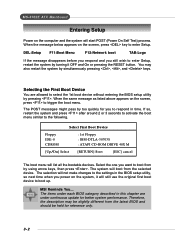
... boot TAB:Logo If the message disappears before you respond and you power on the system, it OFF and On or pressing the RESET button. MSI Reminds You... Selecting the First Boot Device You are under each BIOS category described in time. Therefore, the description may also restart the system by...-ROM DRIVE 40X M [Up/Dn] Select [RETURN] Boot [ESC] cancel The boot menu will boot from by too quickly for better system performance. MS-6702E ATX Mainboard Entering Setup Power on the computer and the system will still use the original first boot device to boot up.
... boot TAB:Logo If the message disappears before you respond and you power on the system, it OFF and On or pressing the RESET button. MSI Reminds You... Selecting the First Boot Device You are under each BIOS category described in time. Therefore, the description may also restart the system by...-ROM DRIVE 40X M [Up/Dn] Select [RETURN] Boot [ESC] cancel The boot menu will boot from by too quickly for better system performance. MS-6702E ATX Mainboard Entering Setup Power on the computer and the system will still use the original first boot device to boot up.
User Guide
Page 43
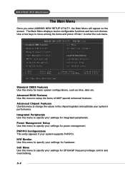
... supports PnP/PCI. Load Fail-Safe Defaults Standard CMOS Features Use this menu to setup the items of AMI® special enhanced features. MS-6702E ATX Mainboard The Main Menu Once you enter AMIBIOS NEW SETUP UTILITY, the Main Menu will appear on the screen. PNP/PCI Configurations This entry appears if...
... supports PnP/PCI. Load Fail-Safe Defaults Standard CMOS Features Use this menu to setup the items of AMI® special enhanced features. MS-6702E ATX Mainboard The Main Menu Once you enter AMIBIOS NEW SETUP UTILITY, the Main Menu will appear on the screen. PNP/PCI Configurations This entry appears if...
User Guide
Page 45
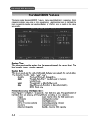
... [Maximum Capacity] Read the maximal HDD capacity 3-6 System Time This allows you to set the system to 31 can be keyed by users. MS-6702E ATX Mainboard Standard CMOS Features The items inside Standard CMOS Features menu are divided into 9 categories. Read-only. Each category includes none, one or more setup items...
... [Maximum Capacity] Read the maximal HDD capacity 3-6 System Time This allows you to set the system to 31 can be keyed by users. MS-6702E ATX Mainboard Standard CMOS Features The items inside Standard CMOS Features menu are divided into 9 categories. Read-only. Each category includes none, one or more setup items...
User Guide
Page 47
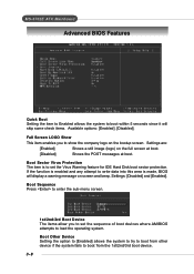
... LOGO Show This item enables you to set the Virus Warning feature for IDE Hard Disk boot sector protection. Settings: [Disabled] and [Enabled]. MS-6702E ATX Mainboard Advanced BIOS Features Quick Boot Setting the item to Enabled allows the system to boot within 5 seconds since it will display a warning message on screen...
... LOGO Show This item enables you to set the Virus Warning feature for IDE Hard Disk boot sector protection. Settings: [Disabled] and [Enabled]. MS-6702E ATX Mainboard Advanced BIOS Features Quick Boot Setting the item to Enabled allows the system to boot within 5 seconds since it will display a warning message on screen...
User Guide
Page 49
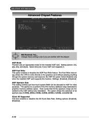
... is a portion of [4MB], [8MB], [16MB], [32MB], [64MB], [128MB], and [256] MB. AGP Mode The item sets an appropriate mode for video purposes. MS-6702E ATX Mainboard Advanced Chipset Features MSI Reminds You... Change these settings only if you are forwarded to the graphics card without any translation.
... is a portion of [4MB], [8MB], [16MB], [32MB], [64MB], [128MB], and [256] MB. AGP Mode The item sets an appropriate mode for video purposes. MS-6702E ATX Mainboard Advanced Chipset Features MSI Reminds You... Change these settings only if you are forwarded to the graphics card without any translation.


