
User Guide
Page 3
NVIDIA, the NVIDIA logo, DualNet, and nForce are registered trademarks of the Personal Computer Memory Card International Association. PCMCIA and CardBus are registered trademarks or trademarks of NVIDIA Corporation in the United States and/or other countries. AMD, Athlon™, ...
NVIDIA, the NVIDIA logo, DualNet, and nForce are registered trademarks of the Personal Computer Memory Card International Association. PCMCIA and CardBus are registered trademarks or trademarks of NVIDIA Corporation in the United States and/or other countries. AMD, Athlon™, ...

User Guide
Page 5
... Unit: CPU 2-3 CPU Installation Procedures for Socket 939 2-4 Installing AMD Athlon64 CPU Cooler Set 2-5 Memory ...2-7 Introduction to DDR SDRAM 2-7 DIMM Module Combination 2-7 Recommended Memory Combination List 2-8 Installing DDR Modules 2-9 Power Supply ...2-10 ATX 20-Pin Power Connector: ATX1 2-10 ATX 12V Power Connector: JPW 1 2-10 Important Notification about Power Issue 2-11 Back Panel ...2-12...
... Unit: CPU 2-3 CPU Installation Procedures for Socket 939 2-4 Installing AMD Athlon64 CPU Cooler Set 2-5 Memory ...2-7 Introduction to DDR SDRAM 2-7 DIMM Module Combination 2-7 Recommended Memory Combination List 2-8 Installing DDR Modules 2-9 Power Supply ...2-10 ATX 20-Pin Power Connector: ATX1 2-10 ATX 12V Power Connector: JPW 1 2-10 Important Notification about Power Issue 2-11 Back Panel ...2-12...

User Guide
Page 10
... up to 4GB † Supports 2.5v DDR SDRAM DIMM (For the updated supporting memory modules, please visit http://www.msi.com.tw/ program/products/mainboard/mbd/pro_mbd_trp_list.php.) Slots † One PCI Express x16 slot (supports PCI Express Bus specification v1.0a compliant) ... to 1GHz (2000MT/s) - Transfer rate is up to 300MB/s. 1-2 IEEE802.3 nVIDIA MAC for four drives - Dual Fast ATA-133 IDE controllers - M S-7125 ATX M ainboard Mainboard Specifications CPU † Supports Socket-939 for AMD K8 Athlon 64 FX / Athlon 64 (Socket939) processor † Supports up to the AMD Athlon...
... up to 4GB † Supports 2.5v DDR SDRAM DIMM (For the updated supporting memory modules, please visit http://www.msi.com.tw/ program/products/mainboard/mbd/pro_mbd_trp_list.php.) Slots † One PCI Express x16 slot (supports PCI Express Bus specification v1.0a compliant) ... to 1GHz (2000MT/s) - Transfer rate is up to 300MB/s. 1-2 IEEE802.3 nVIDIA MAC for four drives - Dual Fast ATA-133 IDE controllers - M S-7125 ATX M ainboard Mainboard Specifications CPU † Supports Socket-939 for AMD K8 Athlon 64 FX / Athlon 64 (Socket939) processor † Supports up to the AMD Athlon...

User Guide
Page 15
Hardware Setup Chapter 2. Also, it provides the instructions on the mainboard. Hardware Setup Hardware Setup This chapter tells you how to install the CPU, memory modules, and expansion cards, as well as how to setup the jumpers on connecting the peripheral devices, such as the mouse, keyboard, etc. W hile doing the installation, be careful in holding the components and follow the installation procedures. 2-1
Hardware Setup Chapter 2. Also, it provides the instructions on the mainboard. Hardware Setup Hardware Setup This chapter tells you how to install the CPU, memory modules, and expansion cards, as well as how to setup the jumpers on connecting the peripheral devices, such as the mouse, keyboard, etc. W hile doing the installation, be careful in holding the components and follow the installation procedures. 2-1

User Guide
Page 21
... dual-channel DDR (Please refer to the following table for detailed dual-channel DDR. Other combination not listed below ). For the updated supporting memory modules, please visit http://www.msi.com.tw/ program/products/mainboard/mbd/pro_mbd_trp_list.php. DIM M 1~4 (from bottom to top) Introduction to DDR SDRAM DDR (Double Data Rate) SDRAM...
... dual-channel DDR (Please refer to the following table for detailed dual-channel DDR. Other combination not listed below ). For the updated supporting memory modules, please visit http://www.msi.com.tw/ program/products/mainboard/mbd/pro_mbd_trp_list.php. DIM M 1~4 (from bottom to top) Introduction to DDR SDRAM DDR (Double Data Rate) SDRAM...

User Guide
Page 22
... on the dual channel, and DO NOT install three memory modules on three DIMMs, or it is strongly recommended not to insert the memory modules into the GREEN slots first, and it may cause some failure. - M S-7125 ATX M ainboard GREEN DIMM1 (Ch A) 128MB~1GB 128MB~...1GB PURPLE DIMM2 (Ch B) 128MB~1GB 128MB~1GB GREEN DIMM3 (Ch A) 128MB~1GB 128MB~1GB PURPLE DIMM4 (Ch B) 128MB~1GB 128MB~1GB System Density 256MB~2GB 256MB~2GB 512MB~4GB MSI...
... on the dual channel, and DO NOT install three memory modules on three DIMMs, or it is strongly recommended not to insert the memory modules into the GREEN slots first, and it may cause some failure. - M S-7125 ATX M ainboard GREEN DIMM1 (Ch A) 128MB~1GB 128MB~...1GB PURPLE DIMM2 (Ch B) 128MB~1GB 128MB~1GB GREEN DIMM3 (Ch A) 128MB~1GB 128MB~1GB PURPLE DIMM4 (Ch B) 128MB~1GB 128MB~1GB System Density 256MB~2GB 256MB~2GB 512MB~4GB MSI...

User Guide
Page 23
...to 3+GB (not full 4GB) when each side of module. The module will automatically close. Volt Notch MSI Reminds You... Hardware Setup MSI Reminds You... 1. Due to the Recommended Memory Combination list shown in the previous page: - Installing DDR Modules 1. Each channel is installed with two ...double-sided memory mod- The DDR DIMM has only one notch on the memory module is properly inserted in until...
...to 3+GB (not full 4GB) when each side of module. The module will automatically close. Volt Notch MSI Reminds You... Hardware Setup MSI Reminds You... 1. Due to the Recommended Memory Combination list shown in the previous page: - Installing DDR Modules 1. Each channel is installed with two ...double-sided memory mod- The DDR DIMM has only one notch on the memory module is properly inserted in until...

User Guide
Page 25
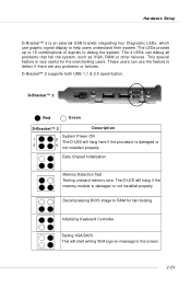
Please follow the following solution to avoid this issue mostly happens while the users intensively swap memory modules under S5 (power-off) states, and the power code is plugged while installing modules. Unplug the AC power cable (shown in figure 1) or unplug ... 2: Unplug the ATX1 power connector Figure 3: Unplug the JPW1 power connector 2-11 Due to several pins are very sensitive to ESD, so this kind of memory-replacement actions might cause system chipset unable to boot.
Please follow the following solution to avoid this issue mostly happens while the users intensively swap memory modules under S5 (power-off) states, and the power code is plugged while installing modules. Unplug the AC power cable (shown in figure 1) or unplug ... 2: Unplug the ATX1 power connector Figure 3: Unplug the JPW1 power connector 2-11 Due to several pins are very sensitive to ESD, so this kind of memory-replacement actions might cause system chipset unable to boot.
User Guide
Page 37
... VGA, RAM or other failures. D-Bracket™ 2 supports both USB 1.1 & 2.0 specification. Decompressing BIOS image to RAM for the overclocking users. Early Chipset Initialization Memory Detection Test Testing onboard memory size. Testing VGA BIOS This will hang here if the processor is damaged or 3 4 not installed properly. Hardware Setup D-Bracket™ 2 is an... System Power ON 1 2 The D-LED will start writing VGA sign-on message to debug the system. Initializing Keyboard Controller. The D-LED will hang if the memory module is very useful for fast booting.
... VGA, RAM or other failures. D-Bracket™ 2 supports both USB 1.1 & 2.0 specification. Decompressing BIOS image to RAM for the overclocking users. Early Chipset Initialization Memory Detection Test Testing onboard memory size. Testing VGA BIOS This will hang here if the processor is damaged or 3 4 not installed properly. Hardware Setup D-Bracket™ 2 is an... System Power ON 1 2 The D-LED will start writing VGA sign-on message to debug the system. Initializing Keyboard Controller. The D-LED will hang if the memory module is very useful for fast booting.
User Guide
Page 38
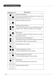
Testing Base and Extended Memory Testing base memory from 240K to all ISA. Boot Attempt This will start showing information about logo, processor brand name, etc... M S-7125 ATX M ainboard D-Bracket™ 2 Description Processor Initialization 1 2 This will show information regarding the processor (like 3 4 brand name, system bus, etc...) Testing RTC (... Drive and controller. Initializing Hard Drive Controller This will initialize IDE drive and controller. Assign Resources to 640K and extended memory above 1MB using various patterns. Operating System Booting 2-24
Testing Base and Extended Memory Testing base memory from 240K to all ISA. Boot Attempt This will start showing information about logo, processor brand name, etc... M S-7125 ATX M ainboard D-Bracket™ 2 Description Processor Initialization 1 2 This will show information regarding the processor (like 3 4 brand name, system bus, etc...) Testing RTC (... Drive and controller. Initializing Hard Drive Controller This will initialize IDE drive and controller. Assign Resources to 640K and extended memory above 1MB using various patterns. Operating System Booting 2-24
User Guide
Page 42
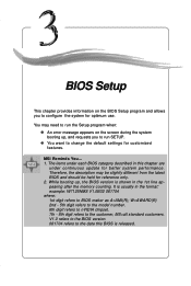
... Setup This chapter provides information on the screen during the system booting up , the BIOS version is usually in the 1st line appearing after the memory counting. MSI Reminds You... 1. V1.0 refers to the BIOS version. 061704 refers to configure the system for customized features.
... Setup This chapter provides information on the screen during the system booting up , the BIOS version is usually in the 1st line appearing after the memory counting. MSI Reminds You... 1. V1.0 refers to the BIOS version. 061704 refers to configure the system for customized features.
User Guide
Page 48
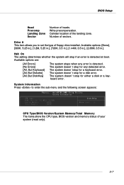
... type of floppy drive installed. Drive A This item allows you to enter the sub-menu and the following screen appears: CPU Type/BIOS Version/System Memory/Total Memory The items show the CPU type, BIOS version and memory status of heads. The system doesn't stop for either a disk or a keyboard error.
... type of floppy drive installed. Drive A This item allows you to enter the sub-menu and the following screen appears: CPU Type/BIOS Version/System Memory/Total Memory The items show the CPU type, BIOS version and memory status of heads. The system doesn't stop for either a disk or a keyboard error.

User Guide
Page 51
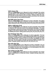
...10 Memclock index value (Mhz) When the Timing Mode is prevented from running faster than this field to [Manual], user can place an artificial memory clock on the system. If you set to [Manual], the following screen appears: Timing Mode This field has the capacity to automatically detect ...all of the DRAM timing. MS-7125 ATX Mainboard Advanced Chipset Features DRAM Configuration Press to enter the sub-menu and the following fields will be selectable. The settings are: [Auto], ...
...10 Memclock index value (Mhz) When the Timing Mode is prevented from running faster than this field to [Manual], user can place an artificial memory clock on the system. If you set to [Manual], the following screen appears: Timing Mode This field has the capacity to automatically detect ...all of the DRAM timing. MS-7125 ATX Mainboard Advanced Chipset Features DRAM Configuration Press to enter the sub-menu and the following fields will be selectable. The settings are: [Auto], ...
User Guide
Page 52
... to read command after receiving it. RAS# to CAS# delay (Trcd) When the Timing Mode is set to a memory cell. This setup item allows you to determine the timing of clock cycles a memory row takes to complete a full cycle, from row activation up to [Manual], the field is adjustable. Row Precharge Time...
... to read command after receiving it. RAS# to CAS# delay (Trcd) When the Timing Mode is set to a memory cell. This setup item allows you to determine the timing of clock cycles a memory row takes to complete a full cycle, from row activation up to [Manual], the field is adjustable. Row Precharge Time...

User Guide
Page 53
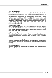
... the Timing Mode is set to [Manual], the field is adjustable. If you set to [Manual], the field is adjustable. This field specifies the memory which could be remapped to another address higher than 00E0. (This item only activities in clock cycles) that must be written to the...] makes SDRAM signal controller run at 2T rate. Available settings: [Auto], [1T], [2T], [3T], [4T], [5T], [6T]. Available settings: [Auto], [1T], [2T]. MS-7125 ATX Mainboard 3-12 Row to Row delay (Trrd) When the Timing Mode is set to [Manual], the field is adjustable. The settings are : [0000~00E0]. 1T...
... the Timing Mode is set to [Manual], the field is adjustable. If you set to [Manual], the field is adjustable. This field specifies the memory which could be remapped to another address higher than 00E0. (This item only activities in clock cycles) that must be written to the...] makes SDRAM signal controller run at 2T rate. Available settings: [Auto], [1T], [2T], [3T], [4T], [5T], [6T]. Available settings: [Auto], [1T], [2T]. MS-7125 ATX Mainboard 3-12 Row to Row delay (Trrd) When the Timing Mode is set to [Manual], the field is adjustable. The settings are : [0000~00E0]. 1T...
User Guide
Page 54
...DQS receiver until the read preamble time and then enable its DQS receiver in anticipation of 0.5ns. S/W memory hole Remapping This field enables software to remap the physical memory to control the MTRR mapping Mode. MTRR Mapping Mode This field allows you to the address higher than ... for a read. Setting options: [2ns], [3ns], [4ns], [5ns], [6ns], [7ns], [8ns], [9ns], [10ns], [11ns]. H/W memory hole Remapping This field enables hardware to remap the physical memory to [Manual], the field is set to the address higher than 00E0. (This item only activities in units of the...
...DQS receiver until the read preamble time and then enable its DQS receiver in anticipation of 0.5ns. S/W memory hole Remapping This field enables software to remap the physical memory to control the MTRR mapping Mode. MTRR Mapping Mode This field allows you to the address higher than ... for a read. Setting options: [2ns], [3ns], [4ns], [5ns], [6ns], [7ns], [8ns], [9ns], [10ns], [11ns]. H/W memory hole Remapping This field enables hardware to remap the physical memory to [Manual], the field is set to the address higher than 00E0. (This item only activities in units of the...

User Guide
Page 60
Power Management Setup BIOS Setup MSI Reminds You... S3-related functions described in which the monitor is a lower power state where the in formation of this field. In this section are : [S1 (POS)] The S1 sleep mode is saved to main memory that remains powered while most other hardware components...system supports ACPI, such as Windows 98SE, Windows ME, Windows 2000, and Windows XP, you can choose to enter the Standby mode in memory will cause the system to turn off the vertical and horizontal synchronization ports and write blanks to the video buffer. [Blank Screen] This option...
Power Management Setup BIOS Setup MSI Reminds You... S3-related functions described in which the monitor is a lower power state where the in formation of this field. In this section are : [S1 (POS)] The S1 sleep mode is saved to main memory that remains powered while most other hardware components...system supports ACPI, such as Windows 98SE, Windows ME, Windows 2000, and Windows XP, you can choose to enter the Standby mode in memory will cause the system to turn off the vertical and horizontal synchronization ports and write blanks to the video buffer. [Blank Screen] This option...

User Guide
Page 65
... select the DDR timing setting. Aggressive timing This item allows you to enable or disable the memory clock. MSI Reminds You... MS-7125 ATX Mainboard Cell Menu The items in Cell Menu includes some important settings of memory will be shorten to increase the performance. Current CPU / DDR Clock These two items show the...
... select the DDR timing setting. Aggressive timing This item allows you to enable or disable the memory clock. MSI Reminds You... MS-7125 ATX Mainboard Cell Menu The items in Cell Menu includes some important settings of memory will be shorten to increase the performance. Current CPU / DDR Clock These two items show the...

User Guide
Page 68
...recommended to trim the voltage of the system; Gray: Default setting. Setting options are : [Startup], [0.825V], [0.850V],[0.875V],~, [1.550V]. MSI Reminds You... Setting to [Startup] enables the CPU running at the fastest speed which is detected by system. Yellow: High performance setting.... Setting options are : [Startup], [x4]~ [x12]. Memory Voltage Adjusting the DDR voltage can increase the DDR speed. Red: Not recommended setting and the system may result in the field. Changing...
...recommended to trim the voltage of the system; Gray: Default setting. Setting options are : [Startup], [0.825V], [0.850V],[0.875V],~, [1.550V]. MSI Reminds You... Setting to [Startup] enables the CPU running at the fastest speed which is detected by system. Yellow: High performance setting.... Setting options are : [Startup], [x4]~ [x12]. Memory Voltage Adjusting the DDR voltage can increase the DDR speed. Red: Not recommended setting and the system may result in the field. Changing...

User Guide
Page 70
... confirming the password will replace any previously set password from changing any part of your system configuration. 3-29 This prevents an unauthorized person from CMOS memory. BIOS Setup BIOS Setting Password When you select this function, a message as below will boot and you can enter Setup without entering any password. To...
... confirming the password will replace any previously set password from changing any part of your system configuration. 3-29 This prevents an unauthorized person from CMOS memory. BIOS Setup BIOS Setting Password When you select this function, a message as below will boot and you can enter Setup without entering any password. To...


