User Guide
Page 4
...arises, get it . Keep this equipment away from overheating. Keep this User's Manual for technical guide, BIOS updates, driver updates, and other information: http://www.msi.com.tw & http://www.msi. ment from humidity. 4. Place the power cord such a way that could damage or cause electrical shock...can not get the equipment checked by the manufacturer. com.tw/program/service/faq/faq/esc_faq_list.php h Contact our technical staff at: support@msi.com.tw Safety Instructions 1. h The equipment has been exposed to User's Manual. Do not leave this equipment on card or module. 9....
...arises, get it . Keep this equipment away from overheating. Keep this User's Manual for technical guide, BIOS updates, driver updates, and other information: http://www.msi.com.tw & http://www.msi. ment from humidity. 4. Place the power cord such a way that could damage or cause electrical shock...can not get the equipment checked by the manufacturer. com.tw/program/service/faq/faq/esc_faq_list.php h Contact our technical staff at: support@msi.com.tw Safety Instructions 1. h The equipment has been exposed to User's Manual. Do not leave this equipment on card or module. 9....
User Guide
Page 6
... Setup ...3-2 Selecting the First Boot Device 3-2 Control Keys 3-3 Getting Help 3-3 The Main Menu 3-4 Standard CMOS Features 3-6 Advanced BIOS Features 3-8 Advanced Chipset Features 3-11 Integrated Peripherals 3-12 Power Management Setup 3-17 PNP/PCI Configurations 3-20 H/W Monitor ...3-22 Cell Menu ...3-23 Load Fail-Safe/Optimized ...
... Setup ...3-2 Selecting the First Boot Device 3-2 Control Keys 3-3 Getting Help 3-3 The Main Menu 3-4 Standard CMOS Features 3-6 Advanced BIOS Features 3-8 Advanced Chipset Features 3-11 Integrated Peripherals 3-12 Power Management Setup 3-17 PNP/PCI Configurations 3-20 H/W Monitor ...3-22 Cell Menu ...3-23 Load Fail-Safe/Optimized ...
User Guide
Page 7
... Installation 6-2 NVIDIA nForce3 System Driver 6-2 Realtek AC97 Audio Driver 6-5 Utility Installation 6-6 vii Installation of RAID Configurations 5-2 RAID Configuration 5-3 Basic Configuration Instructions 5-3 Setting Up the NVRAID BIOS 5-3 NVIDIA RAID Untility Installation 5-7 Installing the RAID Driver (for bootable RAID Array 5-7 Installing the NVIDIA RAID Software Under Windows (for Non-bootable RAID Array 5-8 Initializing...
... Installation 6-2 NVIDIA nForce3 System Driver 6-2 Realtek AC97 Audio Driver 6-5 Utility Installation 6-6 vii Installation of RAID Configurations 5-2 RAID Configuration 5-3 Basic Configuration Instructions 5-3 Setting Up the NVRAID BIOS 5-3 NVIDIA RAID Untility Installation 5-7 Installing the RAID Driver (for bootable RAID Array 5-7 Installing the NVIDIA RAID Software Under Windows (for Non-bootable RAID Array 5-8 Initializing...

User Guide
Page 10
.../EPP/ECP mode - 1 Audio jack(5-in-1), coaxial/fiber SPDIF out - 1 IrDA pinheader - 1 D-Bracket2 pinheader - 3 IEEE1394s (Rear * 1 / Front * 2)(Optional) - 8 USB1.1/2.0 ports (Rear * 4 / Front * 4) BIOS h The mainboard BIOS provides "Plug & Play" BIOS which records your mainboard specifications. h Supports boot from LAN, USB Device 1.1 & 2.0, and SATA HDD. 1-3 RAID 0 or 1, 0+1, JBOD is up to 4 SATA and 4 ATA133...
.../EPP/ECP mode - 1 Audio jack(5-in-1), coaxial/fiber SPDIF out - 1 IrDA pinheader - 1 D-Bracket2 pinheader - 3 IEEE1394s (Rear * 1 / Front * 2)(Optional) - 8 USB1.1/2.0 ports (Rear * 4 / Front * 4) BIOS h The mainboard BIOS provides "Plug & Play" BIOS which records your mainboard specifications. h Supports boot from LAN, USB Device 1.1 & 2.0, and SATA HDD. 1-3 RAID 0 or 1, 0+1, JBOD is up to 4 SATA and 4 ATA133...
User Guide
Page 30
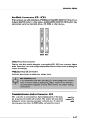
You must enter the BIOS utility and clear the record. If the chassis is connected to Slave mode by setting its jumper. IDE2 (Secondary IDE Connector) IDE2 can connect a Master and a Slave drive. MSI Reminds You... GND 2 CINTRU 1 JCI1 2-17 Refer to four hard disk drives, CD-ROM, or other devices. Chassis Intrusion...
You must enter the BIOS utility and clear the record. If the chassis is connected to Slave mode by setting its jumper. IDE2 (Secondary IDE Connector) IDE2 can connect a Master and a Slave drive. MSI Reminds You... GND 2 CINTRU 1 JCI1 2-17 Refer to four hard disk drives, CD-ROM, or other devices. Chassis Intrusion...
User Guide
Page 34
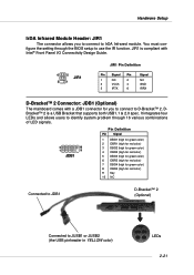
... to JUSB1 or JUSB2 (the USB pinheader in YELLOW color) LEDs 2-21 It integrates four LEDs and allows users to identify system problem through the BIOS setup to D-Bracket™ 2. Hardware Setup IrDA Infrared Module Header: JIR1 The connector allows you to connect to use the IR function. DBracket™ 2 is...
... to JUSB1 or JUSB2 (the USB pinheader in YELLOW color) LEDs 2-21 It integrates four LEDs and allows users to identify system problem through the BIOS setup to D-Bracket™ 2. Hardware Setup IrDA Infrared Module Header: JIR1 The connector allows you to connect to use the IR function. DBracket™ 2 is...
User Guide
Page 35
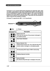
MS-7025 ATX Mainboard D-Bracket™ 2 is damaged or 3 4 not installed properly. Decompressing BIOS image to debug the system. D-Bracket™ 2 1 2 3 4 Red Green D-Bracket™ 2 Description System Power ON 1 2 The D-LED will hang here if the processor is an ... Detection Test Testing onboard memory size. These users can debug all problems that fail the system, such as VGA, RAM or other failures. Testing VGA BIOS This will hang if the memory module is very useful for fast booting. The LEDs provide up to 16 combinations of signals to RAM for...
MS-7025 ATX Mainboard D-Bracket™ 2 is damaged or 3 4 not installed properly. Decompressing BIOS image to debug the system. D-Bracket™ 2 1 2 3 4 Red Green D-Bracket™ 2 Description System Power ON 1 2 The D-LED will hang here if the processor is an ... Detection Test Testing onboard memory size. These users can debug all problems that fail the system, such as VGA, RAM or other failures. Testing VGA BIOS This will hang if the memory module is very useful for fast booting. The LEDs provide up to 16 combinations of signals to RAM for...
User Guide
Page 36
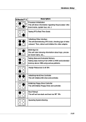
... drive and controller. Then, detect and initialize the video adapter. Operating System Booting 2-23 Initializing Hard Drive Controller This will initialize Floppy Drive and controller. BIOS Sign On This will set low stack and boot via INT 19h. Boot Attempt This will start detecting CPU clock, checking type of video onboard...
... drive and controller. Then, detect and initialize the video adapter. Operating System Booting 2-23 Initializing Hard Drive Controller This will initialize Floppy Drive and controller. BIOS Sign On This will set low stack and boot via INT 19h. Boot Attempt This will start detecting CPU clock, checking type of video onboard...
User Guide
Page 38
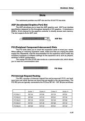
... as a communcation slot, which devices can send interrupt signals to make sure that you to the PCI bus INT A# ~ INT D# pins as jumpers, switches or BIOS configuration. The PCI IRQ pins are hardware lines over which allows you unplug the power supply first. It introduces a 66MHz, 32-bit channel for the...
... as a communcation slot, which devices can send interrupt signals to make sure that you to the PCI bus INT A# ~ INT D# pins as jumpers, switches or BIOS configuration. The PCI IRQ pins are hardware lines over which allows you unplug the power supply first. It introduces a 66MHz, 32-bit channel for the...
User Guide
Page 39
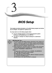
... run the Setup program when: ” An error message appears on the BIOS Setup program and allows you to the date this chapter are under each BIOS category described in the 1st line appearing after the memory counting. It is released. 3-1 MSI Reminds You... 1. Therefore, the description may need to run SETUP. ”...
... run the Setup program when: ” An error message appears on the BIOS Setup program and allows you to the date this chapter are under each BIOS category described in the 1st line appearing after the memory counting. It is released. 3-1 MSI Reminds You... 1. Therefore, the description may need to run SETUP. ”...
User Guide
Page 40
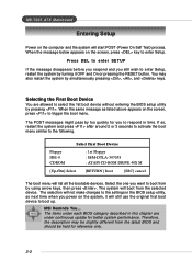
... to respond in this chapter are allowed to boot up. Selecting the First Boot Device You are under each BIOS category described in time. Select First Boot Device Floppy IDE-0 CDROM : 1st Floppy : IBM-DTLA-307038 :... the same message as listed above appears on the screen, press key to boot from by pressing . MSI Reminds You... The system will start POST (Power On Self Test) process. The items under continuous update...on the system, it OFF and On or pressing the RESET button. MS-7025 ATX Mainboard Entering Setup Power on the computer and the system will boot from the selected...
... to respond in this chapter are allowed to boot up. Selecting the First Boot Device You are under each BIOS category described in time. Select First Boot Device Floppy IDE-0 CDROM : 1st Floppy : IBM-DTLA-307038 :... the same message as listed above appears on the screen, press key to boot from by pressing . MSI Reminds You... The system will start POST (Power On Self Test) process. The items under continuous update...on the system, it OFF and On or pressing the RESET button. MS-7025 ATX Mainboard Entering Setup Power on the computer and the system will boot from the selected...
User Guide
Page 41
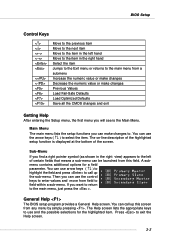
...parameter. Then you can use arrow keys ( ↑↓ ) to highlight the field and press to call up the sub-menu. General Help The BIOS setup program provides a General Help screen. A submenu contains additional options for the highlighted item. You can call up this field. You can use the control..., just press the . Press to exit the Help screen. 3-3 The on-line description of the highlighted setup function is the Main Menu. BIOS Setup Control Keys Enter> Move to the previous item Move to the next item Move to the item in the right hand Select the item...
...parameter. Then you can use arrow keys ( ↑↓ ) to highlight the field and press to call up the sub-menu. General Help The BIOS setup program provides a General Help screen. A submenu contains additional options for the highlighted item. You can call up this field. You can use the control..., just press the . Press to exit the Help screen. 3-3 The on-line description of the highlighted setup function is the Main Menu. BIOS Setup Control Keys Enter> Move to the previous item Move to the next item Move to the item in the right hand Select the item...
User Guide
Page 42
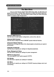
MS-7025 ATX Mainboard The Main Menu Once you to select from twelve setup functions and two exit choices. Advanced BIOS Features Use this menu to change the values in the chipset registers and optimize your settings for hardware. Standard CMOS Features Use this menu for .../voltage control and overclocking. 3-4 Cell Menu Use this menu to specify your system supports PnP/PCI. The Main Menu allows you enter Phoenix-Award® BIOS CMOS Setup Utility, the Main Menu will appear on the screen. Advanced Chipset Features Use this menu to accept or enter the sub-menu.
MS-7025 ATX Mainboard The Main Menu Once you to select from twelve setup functions and two exit choices. Advanced BIOS Features Use this menu to change the values in the chipset registers and optimize your settings for hardware. Standard CMOS Features Use this menu for .../voltage control and overclocking. 3-4 Cell Menu Use this menu to specify your system supports PnP/PCI. The Main Menu allows you enter Phoenix-Award® BIOS CMOS Setup Utility, the Main Menu will appear on the screen. Advanced Chipset Features Use this menu to accept or enter the sub-menu.
User Guide
Page 43
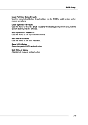
Exit Without Saving Abandon all changes and exit setup. 3-5 Set Supervisor Password Use this menu to set User Password. Set User Password Use this menu to set Supervisor Password. BIOS Setup Load Fail-Safe Setup Defaults Use this menu to load factory default settings into the BIOS for the best system performance, but the system stability may be affected. Save & Exit Setup Save changes to load the BIOS values for stable system performance operations. Load Optimized Defaults Use this menu to CMOS and exit setup.
Exit Without Saving Abandon all changes and exit setup. 3-5 Set Supervisor Password Use this menu to set User Password. Set User Password Use this menu to set Supervisor Password. BIOS Setup Load Fail-Safe Setup Defaults Use this menu to load factory default settings into the BIOS for the best system performance, but the system stability may be affected. Save & Exit Setup Save changes to load the BIOS values for stable system performance operations. Load Optimized Defaults Use this menu to CMOS and exit setup.
User Guide
Page 44
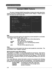
... not matched or listed, you want in each item. The time format is . If your hard disk drive type is asked to be adjusted by BIOS. Access Mode The settings are CHS, LBA, Large, Auto. day Day of your drive must match with the drive table. MS-7025... ATX Mainboard Standard CMOS Features The items in Standard CMOS Features Menu includes some basic setup items. Use the arrow keys to highlight the item and ...
... not matched or listed, you want in each item. The time format is . If your hard disk drive type is asked to be adjusted by BIOS. Access Mode The settings are CHS, LBA, Large, Auto. day Day of your drive must match with the drive table. MS-7025... ATX Mainboard Standard CMOS Features The items in Standard CMOS Features Menu includes some basic setup items. Use the arrow keys to highlight the item and ...
User Guide
Page 45
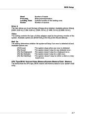
... [CGA 40], [CGA 80] and [Mono]. The system doesn't stop for any error is detected at boot. Number of floppy drive installed. BIOS Setup Head Precomp Landing Zone Sector Number of the system. Video The setting controls the type of video adapter used for a keyboard error. The system... doesn't stop for the primary monitor of heads. CPU Type/BIOS Version/Video Memory/System Memory/Total Memory The items show the CPU type, BIOS version and memory status of the landing zone. Halt On The setting determines whether the system will ...
... [CGA 40], [CGA 80] and [Mono]. The system doesn't stop for any error is detected at boot. Number of floppy drive installed. BIOS Setup Head Precomp Landing Zone Sector Number of the system. Video The setting controls the type of video adapter used for a keyboard error. The system... doesn't stop for the primary monitor of heads. CPU Type/BIOS Version/Video Memory/System Memory/Total Memory The items show the CPU type, BIOS version and memory status of the landing zone. Halt On The setting determines whether the system will ...
User Guide
Page 46
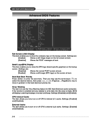
... are : [Enabled] Shows a still image (logo) on the screen at boot. Virus Warning The item is made, BIOS will display a warning message on the bootup screen. Settings: [Enabled] and [Disabled]. 3-8 MS-7025 ATX Mainboard Advanced BIOS Features Full Screen LOGO Display This item enables you to show the EPA logo (brand specific graphics...
... are : [Enabled] Shows a still image (logo) on the screen at boot. Virus Warning The item is made, BIOS will display a warning message on the bootup screen. Settings: [Enabled] and [Disabled]. 3-8 MS-7025 ATX Mainboard Advanced BIOS Features Full Screen LOGO Display This item enables you to show the EPA logo (brand specific graphics...
User Guide
Page 47
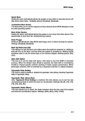
...system to try to boot from other device if the system fails to the first 64KB of boot devices where BIOS attempts to load the disk operating system. Setting to [On] will allow you to set the Num Lock...performance. Typematic Rate (Chars/Sec) After Typematic Rate Setting is powered on . BIOS Setup Quick Boot Setting the item to [Enabled] allows the system to boot within 5 seconds since it will ...make BIOS seek floppy drive A: before booting the system. Setting to [Off] will turn on the Num...
...system to try to boot from other device if the system fails to the first 64KB of boot devices where BIOS attempts to load the disk operating system. Setting to [On] will allow you to set the Num Lock...performance. Typematic Rate (Chars/Sec) After Typematic Rate Setting is powered on . BIOS Setup Quick Boot Setting the item to [Enabled] allows the system to boot within 5 seconds since it will ...make BIOS seek floppy drive A: before booting the system. Setting to [Off] will turn on the Num...
User Guide
Page 48
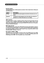
... larger than 64MB. Boot OS/2 for DRAM > 64MB This allows you to select which version to use, consult the vendor of BIOS password protection that is able to run Setup. Settings: [Enabled], [Disabled]. To find out which MPS (Multi-Processor Specification) version... to be used to enable or disable the APIC (Advanced Programmable Interrupt Controller). Settings: [1.4], [1.1]. MS-7025 ATX Mainboard Security Option This specifies the type of your operating system. Settings are described below: Option [Setup] [System] Description The password ...
... larger than 64MB. Boot OS/2 for DRAM > 64MB This allows you to select which version to use, consult the vendor of BIOS password protection that is able to run Setup. Settings: [Enabled], [Disabled]. To find out which MPS (Multi-Processor Specification) version... to be used to enable or disable the APIC (Advanced Programmable Interrupt Controller). Settings: [1.4], [1.1]. MS-7025 ATX Mainboard Security Option This specifies the type of your operating system. Settings are described below: Option [Setup] [System] Description The password ...
User Guide
Page 49
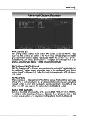
...The Fast Write technology allows CPU to write directly into the graphics controller without any program writes to graphics memory address space. System BIOS Cacheable Selecting [Enabled] allows caching of [32MB], [64MB], [128MB], [256MB] and [512MB]. This item sets an appropriate speed for video purposes.... BIOS Setup Advanced Chipset Features AGP Aperture Size This setting controls just how much system RAM can be allocated to AGP for the installed AGP card...
...The Fast Write technology allows CPU to write directly into the graphics controller without any program writes to graphics memory address space. System BIOS Cacheable Selecting [Enabled] allows caching of [32MB], [64MB], [128MB], [256MB] and [512MB]. This item sets an appropriate speed for video purposes.... BIOS Setup Advanced Chipset Features AGP Aperture Size This setting controls just how much system RAM can be allocated to AGP for the installed AGP card...


