
User Guide
Page 8
Getting Started Chapter 1. The K7N2G Series mainboard is based on NVIDIA® nForce™2 integrated graphics processor (IGP) & NVIDIA® nForce™2 media and communications processor/turbo (MCP2/MCP2-T) for purchasing the K7N2G Series (MS-6570 v1.X) ATX mainboard. Designed to fit the advanced AMD® Athlon™, Athlon™ XP or Duron™ processors, the K7N2G Series mainboard delivers a high performance and professional desktop platform solution. 1-1 Getting Started Getting Started Thank you for optimal system efficiency.
Getting Started Chapter 1. The K7N2G Series mainboard is based on NVIDIA® nForce™2 integrated graphics processor (IGP) & NVIDIA® nForce™2 media and communications processor/turbo (MCP2/MCP2-T) for purchasing the K7N2G Series (MS-6570 v1.X) ATX mainboard. Designed to fit the advanced AMD® Athlon™, Athlon™ XP or Duron™ processors, the K7N2G Series mainboard delivers a high performance and professional desktop platform solution. 1-1 Getting Started Getting Started Thank you for optimal system efficiency.
User Guide
Page 9
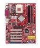
... the MCP2/MCP2-T chipset provides IDE HDD/CD- USB 2.0 EHCI/1.1 OHCI controller - FireWire® for the fastest hard disk throughput - Integrated TV encoder - MS-6570 ATX Mainboard Mainboard Specifications CPU h Supports Socket A (Socket-462) for AMD® Athlon™/Athlon™ XP /Duron™ processors @ FSB 100/133/166 h Supports 600MHz up to...
... the MCP2/MCP2-T chipset provides IDE HDD/CD- USB 2.0 EHCI/1.1 OHCI controller - FireWire® for the fastest hard disk throughput - Integrated TV encoder - MS-6570 ATX Mainboard Mainboard Specifications CPU h Supports Socket A (Socket-462) for AMD® Athlon™/Athlon™ XP /Duron™ processors @ FSB 100/133/166 h Supports 600MHz up to...

User Guide
Page 11
MS-6570 ATX Mainboard Mainboard Layout Top : mouse Bottom: keyboard USB ports SOCKET 462 CFAN1 ATX Power Supply JPW1 FDD 1 Top : Parallel Port Bottom: COM A VGA port Top: LAN jack Bottom: USB ports J10 J11 NVIDIA nForce2 IGP T:Mic M:Line-In B:... 3 PCI Slot 4 SER2 IDE 2 JBAT1 BIOS JAUD1 PCI Slot 5 PROMISE PDC20376 IDE 1 SER1 ACR1 IDE 3 JDLED1 JFP2 JBT1 JUSB2 JFP1 K7N2G-LISR (MS-6570 v1.X) ATX Mainboard 1-4
MS-6570 ATX Mainboard Mainboard Layout Top : mouse Bottom: keyboard USB ports SOCKET 462 CFAN1 ATX Power Supply JPW1 FDD 1 Top : Parallel Port Bottom: COM A VGA port Top: LAN jack Bottom: USB ports J10 J11 NVIDIA nForce2 IGP T:Mic M:Line-In B:... 3 PCI Slot 4 SER2 IDE 2 JBAT1 BIOS JAUD1 PCI Slot 5 PROMISE PDC20376 IDE 1 SER1 ACR1 IDE 3 JDLED1 JFP2 JBT1 JUSB2 JFP1 K7N2G-LISR (MS-6570 v1.X) ATX Mainboard 1-4

User Guide
Page 12
Getting Started Top : mouse Bottom: keyboard USB ports SOCKET 462 CFAN1 ATX Power Supply JPW1 FDD 1 Top : Parallel Port Bottom: COM A VGA port Top: LAN jack Bottom: USB ports T:Mic M:Line-In B:Line-Out J10 J11 NVIDIA nForce2 IGP Winbond W 8362 7H F- AW JTV1 SFAN1 AGP Slot DIMM 1 DIMM 2 DIMM 3 JIR1 JCD Codec JSP2 PCI Slot 1 PCI Slot 2 PCI Slot 3 PCI Slot 4 NVIDIA nForce2 MCP2 IDE 2 BATT + JBAT1 BIOS JAUD1 PCI Slot 5 ACR1 IDE 1 JBT1 JDLED1 JFP2 JUSB2 JFP1 K7N2G-L (MS-6570 v1.X) ATX Mainboard 1-5
Getting Started Top : mouse Bottom: keyboard USB ports SOCKET 462 CFAN1 ATX Power Supply JPW1 FDD 1 Top : Parallel Port Bottom: COM A VGA port Top: LAN jack Bottom: USB ports T:Mic M:Line-In B:Line-Out J10 J11 NVIDIA nForce2 IGP Winbond W 8362 7H F- AW JTV1 SFAN1 AGP Slot DIMM 1 DIMM 2 DIMM 3 JIR1 JCD Codec JSP2 PCI Slot 1 PCI Slot 2 PCI Slot 3 PCI Slot 4 NVIDIA nForce2 MCP2 IDE 2 BATT + JBAT1 BIOS JAUD1 PCI Slot 5 ACR1 IDE 1 JBT1 JDLED1 JFP2 JUSB2 JFP1 K7N2G-L (MS-6570 v1.X) ATX Mainboard 1-5
User Guide
Page 13
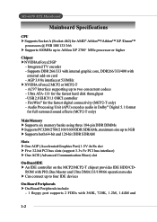
MS-6570 ATX Mainboard MSI Special Features Live Monitor™ The Live Monitor™ is a tool used to view the last search result if there is any. z FAQ- Searches for users to install the "MSI Live Update 2" application. Exits the Live Monitor™ application. Allows you need immediately. z Exit - ...LAN settings right from the dialog box. Double click this icon to perform the functions z Auto Search - You can right-click the MSI Live Monitor icon listed below: to run the application. You can specify how often the system will appear. z View Last Result - ...
MS-6570 ATX Mainboard MSI Special Features Live Monitor™ The Live Monitor™ is a tool used to view the last search result if there is any. z FAQ- Searches for users to install the "MSI Live Update 2" application. Exits the Live Monitor™ application. Allows you need immediately. z Exit - ...LAN settings right from the dialog box. Double click this icon to perform the functions z Auto Search - You can right-click the MSI Live Monitor icon listed below: to run the application. You can specify how often the system will appear. z View Last Result - ...

User Guide
Page 15
... useful for fast booting. D-Bracket™ 2 1 2 3 4 Red Green D-Bracket 2 Description System Power ON 1 2 - Early Chipset Initialization Memory Detection Test - Testing onboard memory size. MS-6570 ATX Mainboard D-Bracket™ 2 (Optional) D-Bracket™ 2 is a USB bracket integrating four Diagnostic LEDs, which use the feature to detect if there are any problems or failures...
... useful for fast booting. D-Bracket™ 2 1 2 3 4 Red Green D-Bracket 2 Description System Power ON 1 2 - Early Chipset Initialization Memory Detection Test - Testing onboard memory size. MS-6570 ATX Mainboard D-Bracket™ 2 (Optional) D-Bracket™ 2 is a USB bracket integrating four Diagnostic LEDs, which use the feature to detect if there are any problems or failures...

User Guide
Page 17
... the items above is a utility you can use the Adjusting Keys to change the minimum and maximum threshold of either Fahrenheit ( ) or Celsius ( ). MS-6570 ATX Mainboard PC Alert™ 4 The PC AlertTM 4 is abnormal, the program main screen will be immediately shown on the Status Area will continue to be shown...
... the items above is a utility you can use the Adjusting Keys to change the minimum and maximum threshold of either Fahrenheit ( ) or Celsius ( ). MS-6570 ATX Mainboard PC Alert™ 4 The PC AlertTM 4 is abnormal, the program main screen will be immediately shown on the Status Area will continue to be shown...
User Guide
Page 19
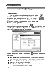
... audio function will not work properly. You can make adjustments in the audio software utility, refer to meet increasing demands for MSI is a convenient tool to Appendix. MS-6570 ATX Mainboard InterVideo WinDVD 4 (Optional) The motherboard comes with 6-channel audio output, you must configure both the WinDVD 4 application and the audio codec's software utility.
... audio function will not work properly. You can make adjustments in the audio software utility, refer to meet increasing demands for MSI is a convenient tool to Appendix. MS-6570 ATX Mainboard InterVideo WinDVD 4 (Optional) The motherboard comes with 6-channel audio output, you must configure both the WinDVD 4 application and the audio codec's software utility.
User Guide
Page 21
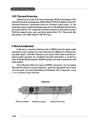
MS-6570 ATX Mainboard CPU Thermal Protection Aimed to Appendix. The S-Bracket offers two types of SPDIF connectors: one to meet your system will then drop down the system ...-Out connectors for AMD Athlon™ XP CPU platform. Using 4- This CPU Thermal Protection mechanism works on S-Bracket, refer to prevent the CPU from overheating, MSI has developed a CPU Thermal Protection mechanism for additional 4-channel analog audio output. S-Bracket (Optional) S-Bracket is for coaxial connection. With the S-Bracket, your own need...
MS-6570 ATX Mainboard CPU Thermal Protection Aimed to Appendix. The S-Bracket offers two types of SPDIF connectors: one to meet your system will then drop down the system ...-Out connectors for AMD Athlon™ XP CPU platform. Using 4- This CPU Thermal Protection mechanism works on S-Bracket, refer to prevent the CPU from overheating, MSI has developed a CPU Thermal Protection mechanism for additional 4-channel analog audio output. S-Bracket (Optional) S-Bracket is for coaxial connection. With the S-Bracket, your own need...

User Guide
Page 25
... arrow Gold arrow Correct CPU placement O Gold arrow Incorrect CPU placement X Press down firmly into the socket and close the lever with your mainboard. 5. Please turn off the power and unplug the power cord before installing the CPU. 2. Please note that any violation of the correct...the pins should point towards the lever pivot. The gold arrow should be completely embedded into the socket. Look for Socket 462 1. MS-6570 ATX Mainboard CPU Installation Procedures for the gold arrow. As the CPU is likely to a 90degree angle. 3. Pull the lever sideways away from the ...
... arrow Gold arrow Correct CPU placement O Gold arrow Incorrect CPU placement X Press down firmly into the socket and close the lever with your mainboard. 5. Please turn off the power and unplug the power cord before installing the CPU. 2. Please note that any violation of the correct...the pins should point towards the lever pivot. The gold arrow should be completely embedded into the socket. Look for Socket 462 1. MS-6570 ATX Mainboard CPU Installation Procedures for the gold arrow. As the CPU is likely to a 90degree angle. 3. Pull the lever sideways away from the ...
User Guide
Page 27
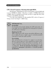
...the power supply's power cord from overheating. MS-6570 ATX Mainboard CPU Clock Frequency Selection through BIOS The hardware configuration for the installed CPU, refer to ensure the safety of the motherboard is designed to support overclocking. MSI Reminds You... Overheating Overheating will seriously damage the CPU and... CPU clock frequency in Chapter 3. We do not guarantee the damages or risks caused by default. Overclocking This motherboard is set the clock frequency for CPU clock frequency of CPU. To set to tolerate such abnormal setting, while doing overclocking.
...the power supply's power cord from overheating. MS-6570 ATX Mainboard CPU Clock Frequency Selection through BIOS The hardware configuration for the installed CPU, refer to ensure the safety of the motherboard is designed to support overclocking. MSI Reminds You... Overheating Overheating will seriously damage the CPU and... CPU clock frequency in Chapter 3. We do not guarantee the damages or risks caused by default. Overclocking This motherboard is set the clock frequency for CPU clock frequency of CPU. To set to tolerate such abnormal setting, while doing overclocking.
User Guide
Page 29
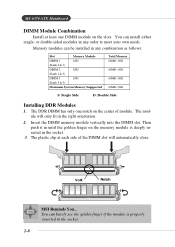
... the DIMM slot will only fit in any order to meet your own needs. Memory modules can be installed in the right orientation. 2. Volt Notch MSI Reminds You... You can install either single- MS-6570 ATX Mainboard DIMM Module Combination Install at each side of module.
... the DIMM slot will only fit in any order to meet your own needs. Memory modules can be installed in the right orientation. 2. Volt Notch MSI Reminds You... You can install either single- MS-6570 ATX Mainboard DIMM Module Combination Install at each side of module.

User Guide
Page 31
... Definition PIN SIGNAL 1 Mouse DATA 2 NC 3 GND 4 VCC 5 Mouse Clock 6 NC DESCRIPTION Mouse DATA No connection Ground +5V Mouse clock No connection 2-10 MS-6570 ATX Mainboard Back Panel The back panel provides the following connectors: Mouse Parallel Keyboard USB COM VGA LAN (Optional) USB MIC L-in L-out Mouse Connector The...
... Definition PIN SIGNAL 1 Mouse DATA 2 NC 3 GND 4 VCC 5 Mouse Clock 6 NC DESCRIPTION Mouse DATA No connection Ground +5V Mouse clock No connection 2-10 MS-6570 ATX Mainboard Back Panel The back panel provides the following connectors: Mouse Parallel Keyboard USB COM VGA LAN (Optional) USB MIC L-in L-out Mouse Connector The...
User Guide
Page 33
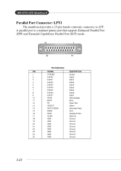
... Ground 19 GND Ground 20 GND Ground 21 GND Ground 22 GND Ground 23 GND Ground 24 GND Ground 25 GND Ground 2-12 MS-6570 ATX Mainboard Parallel Port Connector: LPT1 The mainboard provides a 25-pin female centronic connector as LPT.
... Ground 19 GND Ground 20 GND Ground 21 GND Ground 22 GND Ground 23 GND Ground 24 GND Ground 25 GND Ground 2-12 MS-6570 ATX Mainboard Parallel Port Connector: LPT1 The mainboard provides a 25-pin female centronic connector as LPT.

User Guide
Page 35
... Receive Data Serial Out or Transmit Data Data Terminal Ready) Ground Data Set Ready Request To Send Clear To Send Ring Indicate VGA Connector The mainboard provides a DB 15-pin female connector to connect a VGA monitor. 5 1 15 11 VGA Connector (DB 15-pin) Pin Signal Description 1 RED 2 GREEN 3 BLUE 4 N/C 5 GND 6 GND... 13 Horizontal Sync 14 Vertical Sync 15 SCL 2-14 The port is a 16550A high speed communication port that sends/receives 16 bytes FIFOs. MS-6570 ATX Mainboard Serial Port Connector The mainboard offers one 9-pin male DIN connector as the serial port.
... Receive Data Serial Out or Transmit Data Data Terminal Ready) Ground Data Set Ready Request To Send Clear To Send Ring Indicate VGA Connector The mainboard provides a DB 15-pin female connector to connect a VGA monitor. 5 1 15 11 VGA Connector (DB 15-pin) Pin Signal Description 1 RED 2 GREEN 3 BLUE 4 N/C 5 GND 6 GND... 13 Horizontal Sync 14 Vertical Sync 15 SCL 2-14 The port is a 16550A high speed communication port that sends/receives 16 bytes FIFOs. MS-6570 ATX Mainboard Serial Port Connector The mainboard offers one 9-pin male DIN connector as the serial port.
User Guide
Page 37
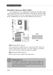
... should always be connected to Slave mode by setting the jumper accordingly. IDE1 can also connect a Master and a Slave drive. MSI Reminds You... MS-6570 ATX Mainboard Hard Disk Connectors: IDE1 & IDE2 The mainboard has a 32-bit Enhanced PCI IDE and Ultra DMA 33/66/ 100/133 controller that provides PIO mode 0~4, Bus Master...
... should always be connected to Slave mode by setting the jumper accordingly. IDE1 can also connect a Master and a Slave drive. MSI Reminds You... MS-6570 ATX Mainboard Hard Disk Connectors: IDE1 & IDE2 The mainboard has a 32-bit Enhanced PCI IDE and Ultra DMA 33/66/ 100/133 controller that provides PIO mode 0~4, Bus Master...
User Guide
Page 39
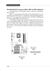
... to 2 hard disk drives, CD-ROM, 120MB Floppy (reserved for detail software installation procedure. 2-18 SER1 SER2 IDE3 MS-6570 ATX Mainboard Hard Disk RAID Connectors: IDE3, SER1 & SER2 (Optional) The mainboard has 3 IDE RAID connectors, which are fully compliant with Serial ATA 1.0 specifications. You can connect to Serial ATA Raid manual for...
... to 2 hard disk drives, CD-ROM, 120MB Floppy (reserved for detail software installation procedure. 2-18 SER1 SER2 IDE3 MS-6570 ATX Mainboard Hard Disk RAID Connectors: IDE3, SER1 & SER2 (Optional) The mainboard has 3 IDE RAID connectors, which are fully compliant with Serial ATA 1.0 specifications. You can connect to Serial ATA Raid manual for...
User Guide
Page 41
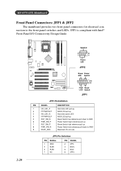
MS-6570 ATX Mainboard Front Panel Connectors: JFP1 & JFP2 The mainboard provides two front panel connectors for electrical connection to GND Reserved. JFP1 is compliant with Intel® Front Panel I/O Connectivity Design Guide. 2-20 Speaker 2 8 1 7 Power ...
MS-6570 ATX Mainboard Front Panel Connectors: JFP1 & JFP2 The mainboard provides two front panel connectors for electrical connection to GND Reserved. JFP1 is compliant with Intel® Front Panel I/O Connectivity Design Guide. 2-20 Speaker 2 8 1 7 Power ...
User Guide
Page 43
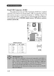
...; I/O Connectivity Design Guide. To use the USB 2.0 ports, you have to PC2PC Bluetooth Manual. 2-22 MS-6570 ATX Mainboard Front USB Connector: JUSB2 The mainboard provides one USB 2.0 pin header JUSB2 that is supplied by Microsoft for Windows® 2000 and XP. JUSB2 Pin Definition... PIN SIGNAL PIN SIGNAL 1 VCC 2 VCC 3 USB0- 4 USB1- 5 USB0+ 6 USB1+ 7 GND 8 GND 9 Key 10 USBOC 2 10 1 9 JUSB2 MSI Reminds You... ...
...; I/O Connectivity Design Guide. To use the USB 2.0 ports, you have to PC2PC Bluetooth Manual. 2-22 MS-6570 ATX Mainboard Front USB Connector: JUSB2 The mainboard provides one USB 2.0 pin header JUSB2 that is supplied by Microsoft for Windows® 2000 and XP. JUSB2 Pin Definition... PIN SIGNAL PIN SIGNAL 1 VCC 2 VCC 3 USB0- 4 USB1- 5 USB0+ 6 USB1+ 7 GND 8 GND 9 Key 10 USBOC 2 10 1 9 JUSB2 MSI Reminds You... ...
User Guide
Page 45
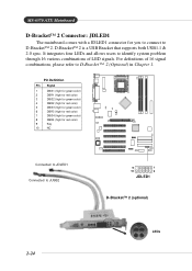
It integrates four LEDs and allows users to D-Bracket™ 2. MS-6570 ATX Mainboard D-Bracket™ 2 Connector: JDLED1 The mainboard comes with a JDLED1 connector for red color) 9 Key 10 NC Connected to JDLED1 Connected to D-Bracket™ 2 (Optional) in Chapter 1. Pin Definition Pin Signal 1 DBG1 (...
It integrates four LEDs and allows users to D-Bracket™ 2. MS-6570 ATX Mainboard D-Bracket™ 2 Connector: JDLED1 The mainboard comes with a JDLED1 connector for red color) 9 Key 10 NC Connected to JDLED1 Connected to D-Bracket™ 2 (Optional) in Chapter 1. Pin Definition Pin Signal 1 DBG1 (...


