User Guide
Page 5
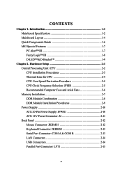
Introduction 1-1 Mainboard Specification 1-2 Mainboard Layout 1-4 Quick Components Guide 1-6 MSI Special Features 1-7 PC Alert™ III 1-7 Fuzzy Logic™ III 1-8 D-LED™&D-Bracket 1-9 Chapter 2. Hardware Setup 2-1 Central Processing Unit: CPU 2-2 CPU Installation Procedures 2-3 Thermal Issue for CPU 2-4 CPU Core Speed Derivation Procedure 2-5 CPU Clock Frequency Selection: JFSB1 2-5 Recommended Computer Case and Axial Fans 2-6 Memory Installation 2-7 DDR Module Combination...
Introduction 1-1 Mainboard Specification 1-2 Mainboard Layout 1-4 Quick Components Guide 1-6 MSI Special Features 1-7 PC Alert™ III 1-7 Fuzzy Logic™ III 1-8 D-LED™&D-Bracket 1-9 Chapter 2. Hardware Setup 2-1 Central Processing Unit: CPU 2-2 CPU Installation Procedures 2-3 Thermal Issue for CPU 2-4 CPU Core Speed Derivation Procedure 2-5 CPU Clock Frequency Selection: JFSB1 2-5 Recommended Computer Case and Axial Fans 2-6 Memory Installation 2-7 DDR Module Combination...

User Guide
Page 9
...1-2 The 66MHz AGP 2.0 compliant interface supports 1x, 2x, and 4x data transfer mode AMD-768™ chipset (492 BGA) - Chapter 1 Mainboard Specification CPU Supports dual Socket A (Socket-462) for AMD Athlon™ MP processors Supports Athlon MP 2100+ or higher Chipset AMD-762™ chipset (949 BGA... 66/33MHz 64/32bit PCI 2.2 compliant bus interface supports up to connect peripherals such as super IO and BIOS - LPC bus to seven bus masters - Note: Because of limitations imposed by the personal computer architecture and BIOS, the user-accessible memory is less than 4 Gbytes even if 4...
...1-2 The 66MHz AGP 2.0 compliant interface supports 1x, 2x, and 4x data transfer mode AMD-768™ chipset (492 BGA) - Chapter 1 Mainboard Specification CPU Supports dual Socket A (Socket-462) for AMD Athlon™ MP processors Supports Athlon MP 2100+ or higher Chipset AMD-762™ chipset (949 BGA... 66/33MHz 64/32bit PCI 2.2 compliant bus interface supports up to connect peripherals such as super IO and BIOS - LPC bus to seven bus masters - Note: Because of limitations imposed by the personal computer architecture and BIOS, the user-accessible memory is less than 4 Gbytes even if 4...
User Guide
Page 13
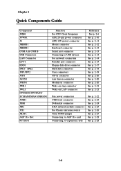
... JCD1 JAUX1 JPHN1 JWR1 JWL1 CPUFAN1/CPUFAN2/ SYSFAN/PSFAN1/NBFAN1 JUSB1 JDB1 JIR1 JCI1 JBAT1 AGP Pro Slot PCI Slots Function For CPU Clock Frequency ATX 20-pin power connector ATX 12V power connector Mouse connector Keyboard connector Serial port connector Connecting to USB devices For network connection Parallel port connector Floppy disk...
... JCD1 JAUX1 JPHN1 JWR1 JWL1 CPUFAN1/CPUFAN2/ SYSFAN/PSFAN1/NBFAN1 JUSB1 JDB1 JIR1 JCI1 JBAT1 AGP Pro Slot PCI Slots Function For CPU Clock Frequency ATX 20-pin power connector ATX 12V power connector Mouse connector Keyboard connector Serial port connector Connecting to USB devices For network connection Parallel port connector Floppy disk...

User Guide
Page 14
Note: Items shown on PC Alert III vary depending on your PC doctor that can find in MSI mainboards. Getting Started MSI Special Features The MSI special features are designed by MSI R & D which are only available in the CD-ROM disk. The utility is an utility you can ...detect the following PC hardware status during real time operation: * monitor CPU & system temperatures * monitor fan speed(s) * monitor system ...
Note: Items shown on PC Alert III vary depending on your PC doctor that can find in MSI mainboards. Getting Started MSI Special Features The MSI special features are designed by MSI R & D which are only available in the CD-ROM disk. The utility is an utility you can ...detect the following PC hardware status during real time operation: * monitor CPU & system temperatures * monitor fan speed(s) * monitor system ...

User Guide
Page 15
CPU Fan - CPU Temp. - Vio - Memory Clock - Chapter 1 Fuzzy Logic™ III The Fuzzy Logic™ III utility allows users to run at the specified frequency each time when the system is powered on. Vcore - CPU Clock - PCI Clock z Adjust CPU FSB Frequency 1-8 AGP Clock - Features: z Display Current System Status - Select the CPU frequency you prefer and click Go to apply the frequency or click Save allowing the system to overclock the CPU FSB (Front Side Bus) frequency in the Windows environment.
CPU Fan - CPU Temp. - Vio - Memory Clock - Chapter 1 Fuzzy Logic™ III The Fuzzy Logic™ III utility allows users to run at the specified frequency each time when the system is powered on. Vcore - CPU Clock - PCI Clock z Adjust CPU FSB Frequency 1-8 AGP Clock - Features: z Display Current System Status - Select the CPU frequency you prefer and click Go to apply the frequency or click Save allowing the system to overclock the CPU FSB (Front Side Bus) frequency in the Windows environment.

User Guide
Page 17
... of the processor and so on ) Testing RTC (Real Time Clock) Initializing Video Interface - Chapter 1 D-LED D-Bracket Description Processor Initialization - Boot Attempt - It will detect CPU clock and check the onboard video type, and then detect and initialize the video adapter. It will test base memory from 240K to all ISA...
... of the processor and so on ) Testing RTC (Real Time Clock) Initializing Video Interface - Chapter 1 D-LED D-Bracket Description Processor Initialization - Boot Attempt - It will detect CPU clock and check the onboard video type, and then detect and initialize the video adapter. It will test base memory from 240K to all ISA...

User Guide
Page 18
... in holding the components and follow the installation procedures. For some components, if you with the information about hardware setup procedures. TOPICS Central Processing Unit: CPU 2-2 Memory 2-7 Power Supply 2-10 Back Panel 2-12 Connectors 2-17 Jumpers 2-27 Slots 2-28 2-1
... in holding the components and follow the installation procedures. For some components, if you with the information about hardware setup procedures. TOPICS Central Processing Unit: CPU 2-2 Memory 2-7 Power Supply 2-10 Back Panel 2-12 Connectors 2-17 Jumpers 2-27 Slots 2-28 2-1

User Guide
Page 19
...To install DUAL CPUs on the board to meet your dealer to prevent overheating. If SINGLE CPU is intended, always install the CPU on the top to purchase and install them before installing CPU(s): 1. When you do not find the Heat Sink and cooling fan, contact your own ... the computer. 2-2 If you are installing the CPU, make sure the CPU has a Heat Sink and a cooling fan attached on the CPU1 socket. The mainboard uses two CPU sockets called Socket A for easy CPU installation. Chapter 2 Central Processing Unit: CPU The MSI mainboard supports Single/Dual AMD® AthlonTM MP ...
...To install DUAL CPUs on the board to meet your dealer to prevent overheating. If SINGLE CPU is intended, always install the CPU on the top to purchase and install them before installing CPU(s): 1. When you do not find the Heat Sink and cooling fan, contact your own ... the computer. 2-2 If you are installing the CPU, make sure the CPU has a Heat Sink and a cooling fan attached on the CPU1 socket. The mainboard uses two CPU sockets called Socket A for easy CPU installation. Chapter 2 Central Processing Unit: CPU The MSI mainboard supports Single/Dual AMD® AthlonTM MP ...

User Guide
Page 20
Pull the lever sideways away from overheating. 2-3 Overheating will only fit in the correct orientation. always make sure the cooling fan can work properly to protect the CPU from the socket. Hardware Setup CPU Installation Procedures 1. Hold the CPU down firmly, and then close the lever to a 90-degree angle. The CPU will seriously damage the CPU and system, WARNING! Look for the cut edge should point towards the lever pivot. Sliding Plate Open Lever 2. Cut edge 3. The cut edge. Then, raise the lever up to Close Lever complete the installation.
Pull the lever sideways away from overheating. 2-3 Overheating will only fit in the correct orientation. always make sure the cooling fan can work properly to protect the CPU from the socket. Hardware Setup CPU Installation Procedures 1. Hold the CPU down firmly, and then close the lever to a 90-degree angle. The CPU will seriously damage the CPU and system, WARNING! Look for the cut edge should point towards the lever pivot. Sliding Plate Open Lever 2. Cut edge 3. The cut edge. Then, raise the lever up to Close Lever complete the installation.

User Guide
Page 21
... processor technology pushes to reliable operation. These are securely fastened and in the specified thermal requirements. Then, make sure that the CPU and heatsink are needed to improve heat dissipation. As such, the processor must be maintained in good contact with a speed of high performance thermal interface ...
... processor technology pushes to reliable operation. These are securely fastened and in the specified thermal requirements. Then, make sure that the CPU and heatsink are needed to improve heat dissipation. As such, the processor must be maintained in good contact with a speed of high performance thermal interface ...

User Guide
Page 22
... speed = Host Clock x Core/Bus ratio = 100MHzx7 = 700MHz CPU Clock Frequency Selection: JFSB1 The default hardware configuration for CPU Clock Frequency is set at 100 MHz. While replacing the CPU, always turn off the ATX power supply or unplug the power cable of the ATX power supply from grounded outlet first to 133 MHz by...
... speed = Host Clock x Core/Bus ratio = 100MHzx7 = 700MHz CPU Clock Frequency Selection: JFSB1 The default hardware configuration for CPU Clock Frequency is set at 100 MHz. While replacing the CPU, always turn off the ATX power supply or unplug the power cable of the ATX power supply from grounded outlet first to 133 MHz by...

User Guide
Page 23
... flows out) MS-6501 ATX Computer Case 2-6 Chapter 2 Recommended Computer Case and Axial Fans To accommodate the MS-6501 mainboard, Axial Fans and other required components, we strongly suggest that you add two axial fans to the system. To maintain a well-ventilated operating environment and prevent CPU overheating problems, we recommend ...that you use the ATX computer case.
... flows out) MS-6501 ATX Computer Case 2-6 Chapter 2 Recommended Computer Case and Axial Fans To accommodate the MS-6501 mainboard, Axial Fans and other required components, we strongly suggest that you add two axial fans to the system. To maintain a well-ventilated operating environment and prevent CPU overheating problems, we recommend ...that you use the ATX computer case.

User Guide
Page 28
J4 4 2 3 1 Pin Definition PIN SIGNAL 1 GND 2 GND 3 12V 4 12V Note: Always make sure to connect a power cable to the J4 to ensure that CPU will work properly with sufficient power input. 2-11 Even if you do not intend to use AGP Pro card, you still have to connect the J4 in order to provide power for the CPU & the AGP Pro card. Hardware Setup ATX 12V Power Connector: J4 This 12V power connector is used to provide power for the CPU & the AGP Pro card.
J4 4 2 3 1 Pin Definition PIN SIGNAL 1 GND 2 GND 3 12V 4 12V Note: Always make sure to connect a power cable to the J4 to ensure that CPU will work properly with sufficient power input. 2-11 Even if you do not intend to use AGP Pro card, you still have to connect the J4 in order to provide power for the CPU & the AGP Pro card. Hardware Setup ATX 12V Power Connector: J4 This 12V power connector is used to provide power for the CPU & the AGP Pro card.

User Guide
Page 34
FDD1 2-17 Floppy Disk Drive Connector: FDD1 The mainboard provides a standard floppy disk drive connector that supports 360K, 720K, 1.2M, 1.44M and 2.88M floppy disk types. Hardware Setup Connectors The mainboard provides connectors to connect to FDD, IDE HDD, case, modem, LAN, USB Ports, IR module and CPU/System FAN.
FDD1 2-17 Floppy Disk Drive Connector: FDD1 The mainboard provides a standard floppy disk drive connector that supports 360K, 720K, 1.2M, 1.44M and 2.88M floppy disk types. Hardware Setup Connectors The mainboard provides connectors to connect to FDD, IDE HDD, case, modem, LAN, USB Ports, IR module and CPU/System FAN.

User Guide
Page 39
...) support system cooling fan with speed sensor to take note that will automatically control the CPU Fan speed according to the actual CPU temeperature. 2-22 When connecting the wire to the connectors, always take advantage of the CPU fan control. GND +12V SENSOR CPUFAN2 SENSOR +12V GND PSFAN1 GND +12V SENSOR CPUFAN1 +12V... GND NBFAN1 GND +12V SENSOR SYSFAN Note: 1. If the mainboard has a System Hardware Monitor chipset on-board, you must use a specially designed fan with +12V. CPU Fan supports the fan control. Always consult the vendor for proper...
...) support system cooling fan with speed sensor to take note that will automatically control the CPU Fan speed according to the actual CPU temeperature. 2-22 When connecting the wire to the connectors, always take advantage of the CPU fan control. GND +12V SENSOR CPUFAN2 SENSOR +12V GND PSFAN1 GND +12V SENSOR CPUFAN1 +12V... GND NBFAN1 GND +12V SENSOR SYSFAN Note: 1. If the mainboard has a System Hardware Monitor chipset on-board, you must use a specially designed fan with +12V. CPU Fan supports the fan control. Always consult the vendor for proper...

User Guide
Page 54
...No warning message to appear when anything attempts to write data into cache memory, for IDE Hard Disk boot sector protection. When the CPU requests data, the system transfers the requested data from the main DRAM into this function is much faster than conventional DRAM (system memory... a warning message to appear when anything attempts to choose the VIRUS Warning feature for even faster access by the CPU. Settings are: Enabled and Disabled. 3-8 CPU Internal /External Cache Cache memory is additional memory that is enabled and someone attempts to access the boot sector of...
...No warning message to appear when anything attempts to write data into cache memory, for IDE Hard Disk boot sector protection. When the CPU requests data, the system transfers the requested data from the main DRAM into this function is much faster than conventional DRAM (system memory... a warning message to appear when anything attempts to choose the VIRUS Warning feature for even faster access by the CPU. Settings are: Enabled and Disabled. 3-8 CPU Internal /External Cache Cache memory is additional memory that is enabled and someone attempts to access the boot sector of...

User Guide
Page 58
... screen no matter how you enable or disable this area is reserved, it cannot be used for ISA adapter ROM. The Fast Write technology allows CPU to set to use this BIOS option is just a service to old AMD users and should not be considered as a solution to the AGP without...
... screen no matter how you enable or disable this area is reserved, it cannot be used for ISA adapter ROM. The Fast Write technology allows CPU to set to use this BIOS option is just a service to old AMD users and should not be considered as a solution to the AGP without...

User Guide
Page 59
..., 40h, 60h, 80h, C0h, FFh. To ensure optimal operation, it is hidden if both processors are running. Note: This item is recommended that you to CPU pipe stages for optimal performance. AGP Secondary Lat Timer This allows you set this option to set the AGP Secondary Lat Timer. The settings are...
..., 40h, 60h, 80h, C0h, FFh. To ensure optimal operation, it is hidden if both processors are running. Note: This item is recommended that you to CPU pipe stages for optimal performance. AGP Secondary Lat Timer This allows you set this option to set the AGP Secondary Lat Timer. The settings are...

User Guide
Page 65
...), S3 (STR), S1 & S3. ACPI Suspend Type This item specifies the power saving modes for ACPI function. S1 (POS) The S1 sleeping state is lost (CPU or chip set) and hardware main- 3-19 In this state, no system context is low wake-up latency sleeping state. AWARD® BIOS Setup Power...
...), S3 (STR), S1 & S3. ACPI Suspend Type This item specifies the power saving modes for ACPI function. S1 (POS) The S1 sleeping state is lost (CPU or chip set) and hardware main- 3-19 In this state, no system context is low wake-up latency sleeping state. AWARD® BIOS Setup Power...

User Guide
Page 66
...(saves the state of Suspend mode. Hardware maintains memory context and restores some CPU and L2 configuration context. Power Management This item is blanked. Settings are : Blank Screen, V/H SYNC+Blank ...and DPMS Support. CPU, cache, and chipset context are : 30 Sec, 1/4/10/20/30 Min, 1 Hour and ... low wake-up latency sleeping sate where all devices except the CPU will cause the system to disk and then powers off the system) and PwrOn Suspend (the CPU and core system remain powered on in a very low-power ...
...(saves the state of Suspend mode. Hardware maintains memory context and restores some CPU and L2 configuration context. Power Management This item is blanked. Settings are : Blank Screen, V/H SYNC+Blank ...and DPMS Support. CPU, cache, and chipset context are : 30 Sec, 1/4/10/20/30 Min, 1 Hour and ... low wake-up latency sleeping sate where all devices except the CPU will cause the system to disk and then powers off the system) and PwrOn Suspend (the CPU and core system remain powered on in a very low-power ...

