
User Guide
Page 3
Visit the MSI website for DIY users. Better yet, the power calculator provides accurate estimates of power unit capacity for technical guide, BIOS updates, driver updates, and other information: http://www.msi.com/service/download/ Contact our technical staff at: http://support.msi.com iii Preface Preface Technical Support If a problem arises with your place of choices and, if product details are required, you may easily download user manuals within...
Visit the MSI website for DIY users. Better yet, the power calculator provides accurate estimates of power unit capacity for technical guide, BIOS updates, driver updates, and other information: http://www.msi.com/service/download/ Contact our technical staff at: http://support.msi.com iii Preface Preface Technical Support If a problem arises with your place of choices and, if product details are required, you may easily download user manuals within...
User Guide
Page 11
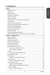
...Assembly Precautions 1-3 Motherboard Specifications 1-4 Connectors Quick Guide 1-7 Back Panel Quick Guide 1-9 CPU (Central Processing Unit 1-11 Introduction to the LGA 1150 CPU 1-11 CPU & Heatsink Installation 1-12 Memory 1-15 Dual-Channel mode Population Rule 1-15 Mounting Screw Holes 1-16 Power Supply 1-17 JPWR1~2: ATX Power Connectors 1-17 Expansion Slots 1-18 PCI_E1~4: PCIe Expansion Slots 1-18 Video/ Graphics Cards 1-19 Single Video Card Installation 1-19 AMD CrossFire™ (Multi-GPU) Technology 1-20 Internal Connectors 1-22 SATA1~6: SATA Connectors 1-22 xi Preface
...Assembly Precautions 1-3 Motherboard Specifications 1-4 Connectors Quick Guide 1-7 Back Panel Quick Guide 1-9 CPU (Central Processing Unit 1-11 Introduction to the LGA 1150 CPU 1-11 CPU & Heatsink Installation 1-12 Memory 1-15 Dual-Channel mode Population Rule 1-15 Mounting Screw Holes 1-16 Power Supply 1-17 JPWR1~2: ATX Power Connectors 1-17 Expansion Slots 1-18 PCI_E1~4: PCIe Expansion Slots 1-18 Video/ Graphics Cards 1-19 Single Video Card Installation 1-19 AMD CrossFire™ (Multi-GPU) Technology 1-20 Internal Connectors 1-22 SATA1~6: SATA Connectors 1-22 xi Preface

User Guide
Page 19
... LAN (RJ45) port ■ 6x audio jacks ■ 1x 24-pin ATX main power connector ■ 1x 4-pin ATX 12V power connector ■ 6x SATA connectors ■ 3x USB 2.0 connectors (supports additional 6 USB 2.0 ports) (for Z87M-G43/ H87M-G43) ■ 2x USB 2.0 connectors (supports additional 4 USB 2.0 ports) (for B85M-G43) ■ 1x USB 3.0 connector (supports additional 2 USB 3.0 ports) ■ 1x 4-pin CPU fan connector ■ 2x 4-pin system fan connectors ■ 1x Clear CMOS jumper ■ 1x Front panel audio connector ■ 2x System panel connectors ■ 1x Chassis Intrusion...
... LAN (RJ45) port ■ 6x audio jacks ■ 1x 24-pin ATX main power connector ■ 1x 4-pin ATX 12V power connector ■ 6x SATA connectors ■ 3x USB 2.0 connectors (supports additional 6 USB 2.0 ports) (for Z87M-G43/ H87M-G43) ■ 2x USB 2.0 connectors (supports additional 4 USB 2.0 ports) (for B85M-G43) ■ 1x USB 3.0 connector (supports additional 2 USB 3.0 ports) ■ 1x 4-pin CPU fan connector ■ 2x 4-pin system fan connectors ■ 1x Clear CMOS jumper ■ 1x Front panel audio connector ■ 2x System panel connectors ■ 1x Chassis Intrusion...

User Guide
Page 22
... Back Panel CPU LGA1150 CPU Socket CPUFAN1,SYSFAN1~2 Fan Power Connectors DIMM1~4 DDR3 Memory Slots JAUD1 Front Panel Audio Connector JBAT1 Clear CMOS Jumper JCI1 Chassis Intrusion Connector JCOM1 Serial Port Connector JFP1, JFP2 System Panel Connectors JLPT1 Parallel Port Connector JPWR1~2 ATX Power Connectors JTPM1 TPM Module Connector JUSB1~3 USB 2.0 Expansion Connectors JUSB4 USB 3.0 Expansion Connector PCI_E1~4 PCIe Expansion Slots SATA1~6 SATA Connectors Page 1-9 1-11 1-23 1-15 1-26 1-29 1-28 1-27 1-24 1-28 1-17 1-27 1-25 1-26 1-18 1-22 Getting Started...
... Back Panel CPU LGA1150 CPU Socket CPUFAN1,SYSFAN1~2 Fan Power Connectors DIMM1~4 DDR3 Memory Slots JAUD1 Front Panel Audio Connector JBAT1 Clear CMOS Jumper JCI1 Chassis Intrusion Connector JCOM1 Serial Port Connector JFP1, JFP2 System Panel Connectors JLPT1 Parallel Port Connector JPWR1~2 ATX Power Connectors JTPM1 TPM Module Connector JUSB1~3 USB 2.0 Expansion Connectors JUSB4 USB 3.0 Expansion Connector PCI_E1~4 PCIe Expansion Slots SATA1~6 SATA Connectors Page 1-9 1-11 1-23 1-15 1-26 1-29 1-28 1-27 1-24 1-28 1-17 1-27 1-25 1-26 1-18 1-22 Getting Started...

User Guide
Page 31
... that all the power cables are securely connected to a proper ATX power supply to install power supply connectors. To connect the ATX power supply, align the power supply cable with the connector and firmly press the cable into the connector. Chapter 1 Power Supply Video Demonstration Watch the video to learn how to ensure stable operation of the motherboard. 1-17 Getting Started http://youtu.be hooked on the power cable should be /gkDYyR_83I4 JPWR1~2: ATX Power Connectors These connectors allow you to connect an ATX power supply.
... that all the power cables are securely connected to a proper ATX power supply to install power supply connectors. To connect the ATX power supply, align the power supply cable with the connector and firmly press the cable into the connector. Chapter 1 Power Supply Video Demonstration Watch the video to learn how to ensure stable operation of the motherboard. 1-17 Getting Started http://youtu.be hooked on the power cable should be /gkDYyR_83I4 JPWR1~2: ATX Power Connectors These connectors allow you to connect an ATX power supply.

User Guide
Page 65
.... Gen X [Auto] Sets PCI Express protocol for detailed settings. Chapter 3 3-7 BIOS Setup Press to indicate the S3 state. ▶ Integrated Peripherals Sets integrated peripherals' parameters, such as first and second PCIe x16 slots. [Auto] Enables all PCIe Gen1, Gen2 and Gen3. This item will support Ipv4 protocol. PEG0, PEG1 are as LAN, HDD, USB and audio. Press to enter the sub-menu. ▶ Onboard LAN Controller [Enabled] Enables or disables the onboard LAN controller. ▶ LAN Option ROM [Disabled] Enables or disables the legacy network Boot Option ROM for...
.... Gen X [Auto] Sets PCI Express protocol for detailed settings. Chapter 3 3-7 BIOS Setup Press to indicate the S3 state. ▶ Integrated Peripherals Sets integrated peripherals' parameters, such as first and second PCIe x16 slots. [Auto] Enables all PCIe Gen1, Gen2 and Gen3. This item will support Ipv4 protocol. PEG0, PEG1 are as LAN, HDD, USB and audio. Press to enter the sub-menu. ▶ Onboard LAN Controller [Enabled] Enables or disables the onboard LAN controller. ▶ LAN Option ROM [Disabled] Enables or disables the legacy network Boot Option ROM for...

User Guide
Page 66
...Audio Controller [Enabled] Enables or disables the onboard High Definition Audio controller. ▶ HPET [Enabled] The HPET (High Precision Event Timers) is a component which is part of system memory allocated to the onboard graphics. AHCI (Advanced Host Controller Interface) offers some advanced features to enable or disable the SATA hot plug support. Press to it will appear when the "SATA Mode" set to [AHCI]/ [RAID]. [Enabled] Enables hot plug support for the SATA ports. [Disabled] Disables hot plug support for SATA storage devices. ▶ SATA1~6 Hot Plug [Disabled] Allows user...
...Audio Controller [Enabled] Enables or disables the onboard High Definition Audio controller. ▶ HPET [Enabled] The HPET (High Precision Event Timers) is a component which is part of system memory allocated to the onboard graphics. AHCI (Advanced Host Controller Interface) offers some advanced features to enable or disable the SATA hot plug support. Press to it will appear when the "SATA Mode" set to [AHCI]/ [RAID]. [Enabled] Enables hot plug support for the SATA ports. [Disabled] Disables hot plug support for SATA storage devices. ▶ SATA1~6 Hot Plug [Disabled] Allows user...

User Guide
Page 68
... [Auto] Sets serial port 0 (COM). ▶ RapidStart Display Save/Restore [Enabled] Enables or disables the Intel Rapid Start Display screen to be saved before the system enters sleep mode. Chapter 3 BIOS Setup 3-10 If set to "Auto", BIOS will restore the screen when wakened. [Enabled] Enables this function. [Disabled] Disables this feature. ▶ USB Configuration Sets the onboard USB controller and device function. Press to enter the submenu. ▶ USB Controller [Enabled] Enables or disables the onboard USB controller. ▶ Legacy USB Support [Enabled] Sets Legacy USB...
... [Auto] Sets serial port 0 (COM). ▶ RapidStart Display Save/Restore [Enabled] Enables or disables the Intel Rapid Start Display screen to be saved before the system enters sleep mode. Chapter 3 BIOS Setup 3-10 If set to "Auto", BIOS will restore the screen when wakened. [Enabled] Enables this function. [Disabled] Disables this feature. ▶ USB Configuration Sets the onboard USB controller and device function. Press to enter the submenu. ▶ USB Controller [Enabled] Enables or disables the onboard USB controller. ▶ Legacy USB Support [Enabled] Sets Legacy USB...

User Guide
Page 69
... periodically waking your system from sleep mode. Chapter 3 3-11 BIOS Setup This feature can set it manually. ▶ Device Mode [Printer Mode] Selects an operating mode for parallel port. [Printer Mode] Printer port mode [SPP] Standard Parallel Port mode [EPP-1.9/ 1.7 + SPP] Enhanced Parallel Port-1.9/ 1.7 mode + Standard Parallel Port mode. [ECP] Extended Capability Port mode [ECP + EPP-1.9/ 1.7] Extended Capability Port mode + Enhanced Parallel Port-1.9/ 1.7 mode. ▶ Intel(R) Smart Connect Configuration Sets Intel Smart Connect Technology for the...
... periodically waking your system from sleep mode. Chapter 3 3-11 BIOS Setup This feature can set it manually. ▶ Device Mode [Printer Mode] Selects an operating mode for parallel port. [Printer Mode] Printer port mode [SPP] Standard Parallel Port mode [EPP-1.9/ 1.7 + SPP] Enhanced Parallel Port-1.9/ 1.7 mode + Standard Parallel Port mode. [ECP] Extended Capability Port mode [ECP + EPP-1.9/ 1.7] Extended Capability Port mode + Enhanced Parallel Port-1.9/ 1.7 mode. ▶ Intel(R) Smart Connect Configuration Sets Intel Smart Connect Technology for the...
User Guide
Page 70
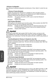
... enter to BIOS setup directly at next boot. ▶ Fast Boot [Enabled for Windows 8, Disabled for other operating systems. Before enabling this item, make sure all installed devices & utilities (hardware & software) should meet the Windows 8 requirements. [Enabled] The system will switch to UEFI mode to meet the Windows 8 requirement. [Disabled] Disables this function. ▶ MSI Fast Boot [Disabled] MSI Fast Boot is disabled. [Enabled] Enables the Fast Boot configuration. [Disabled] Disables the Fast Boot configuration. ▶ USB Support [Full Initial] Disabling the USB devices...
... enter to BIOS setup directly at next boot. ▶ Fast Boot [Enabled for Windows 8, Disabled for other operating systems. Before enabling this item, make sure all installed devices & utilities (hardware & software) should meet the Windows 8 requirements. [Enabled] The system will switch to UEFI mode to meet the Windows 8 requirement. [Disabled] Disables this function. ▶ MSI Fast Boot [Disabled] MSI Fast Boot is disabled. [Enabled] Enables the Fast Boot configuration. [Disabled] Disables the Fast Boot configuration. ▶ USB Support [Full Initial] Disabling the USB devices...

User Guide
Page 72
... different sleep modes. Press to enter the sub-menu. ▶ Wake Up Event By [BIOS] Selects the wake up event by BIOS or operating system. [BIOS] Activates the following items, and use these fields (using the and to select the date & time settings). ▶ Resume By PCI or PCI-E Device [Disabled] Disables or enables the system wake up by PCI or PCI express device. [Enabled] Enables the system to be awakened from the power saving modes when...
... different sleep modes. Press to enter the sub-menu. ▶ Wake Up Event By [BIOS] Selects the wake up event by BIOS or operating system. [BIOS] Activates the following items, and use these fields (using the and to select the date & time settings). ▶ Resume By PCI or PCI-E Device [Disabled] Disables or enables the system wake up by PCI or PCI express device. [Enabled] Enables the system to be awakened from the power saving modes when...

User Guide
Page 73
...to change the BIOS items. ▶ User Password Sets User Password for system security. Chapter 3 3-15 BIOS Setup Enters the administrator password if set password from accessing the system. Only the user who has the key with the flash drive can enter the setup and OS without showing the POST screen. [Disabled] Shows the POST messages at the USB flash drive to prevent other people from CMOS memory. The password typed now will appear on OS installation requirement. [UEFI] Enables UEFI BIOS boot mode support only. [LEGACY+UEFI] Enables both Legacy BIOS boot mode...
...to change the BIOS items. ▶ User Password Sets User Password for system security. Chapter 3 3-15 BIOS Setup Enters the administrator password if set password from accessing the system. Only the user who has the key with the flash drive can enter the setup and OS without showing the POST screen. [Disabled] Shows the POST messages at the USB flash drive to prevent other people from CMOS memory. The password typed now will appear on OS installation requirement. [UEFI] Enables UEFI BIOS boot mode support only. [LEGACY+UEFI] Enables both Legacy BIOS boot mode...

User Guide
Page 74
... chassis is used to discard current all changes and restore to the previous values. ▶ Restore Defaults This item is opened, the system will record and issue a warning message. This it will return to [Enabled] later. [Options: Disabled, Enabled, Reset] Save & Exit ▶ Discard Changes and Exit Exit BIOS setup without saving any change. Chapter 3 BIOS Setup 3-16 To clear the warning message, set the item to [Reset...
... chassis is used to discard current all changes and restore to the previous values. ▶ Restore Defaults This item is opened, the system will record and issue a warning message. This it will return to [Enabled] later. [Options: Disabled, Enabled, Reset] Save & Exit ▶ Discard Changes and Exit Exit BIOS setup without saving any change. Chapter 3 BIOS Setup 3-16 To clear the warning message, set the item to [Reset...
User Guide
Page 76
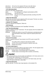
.... [Disabled] Disables this function. ▶ OC Genie Switch [Gear1] Selects a kind of overclocking profiles for extreme overclocking. Chapter 3 BIOS Setup 3-18 This item appears when "OC Genie Function Control" sets to [By BIOS Options]. [Gear1] Enables Gear1 overclocking profile for overclocking. [Gear2] Enables Gear2 overclocking profile for OC Genie Function. [Next Boot] CPU will run the adjusted CPU base clock after enabling the OC Genie function. • Updating BIOS or clearing CMOS is used to determine CPU clock speed.
.... [Disabled] Disables this function. ▶ OC Genie Switch [Gear1] Selects a kind of overclocking profiles for extreme overclocking. Chapter 3 BIOS Setup 3-18 This item appears when "OC Genie Function Control" sets to [By BIOS Options]. [Gear1] Enables Gear1 overclocking profile for overclocking. [Gear2] Enables Gear2 overclocking profile for OC Genie Function. [Next Boot] CPU will run the adjusted CPU base clock after enabling the OC Genie function. • Updating BIOS or clearing CMOS is used to determine CPU clock speed.
User Guide
Page 77
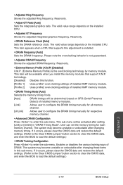
... overclocking technology by memory module. technology. [Disabled] Disables this sub-menu. This item appears when a CPU that support X.M.P. The valid value range depends on the installed CPU. Please note the overclocking behavior is not guaranteed. ▶ Adjusted DRAM Frequency Shows the adjusted DRAM frequency. If it occurs, please clear the CMOS data and restore the default settings. (Refer to the Clear CMOS jumper/ button section to clear the CMOS data, and enter the BIOS to load the default settings.) ▶ DRAM Training Configuration...
... overclocking technology by memory module. technology. [Disabled] Disables this sub-menu. This item appears when a CPU that support X.M.P. The valid value range depends on the installed CPU. Please note the overclocking behavior is not guaranteed. ▶ Adjusted DRAM Frequency Shows the adjusted DRAM frequency. If it occurs, please clear the CMOS data and restore the default settings. (Refer to the Clear CMOS jumper/ button section to clear the CMOS data, and enter the BIOS to load the default settings.) ▶ DRAM Training Configuration...
User Guide
Page 79
... boot when the CPU or memory has been replaced. [Enabled] The system will set memory voltage automatically or you are overclocking because even a slight jitter can set it manually. ▶ Current DRAM Voltage Shows current memory voltage. ▶ Internal VR OVP OCP Protection [Auto] Enables or disables the over-voltage protection and over-current protection for CPU internal VR (Voltage Regulator). [Auto] This setting will be configured automatically by BIOS. [Enabled] Sets the voltage limit on the CPU internal VR for over-voltage...
... boot when the CPU or memory has been replaced. [Enabled] The system will set memory voltage automatically or you are overclocking because even a slight jitter can set it manually. ▶ Current DRAM Voltage Shows current memory voltage. ▶ Internal VR OVP OCP Protection [Auto] Enables or disables the over-voltage protection and over-current protection for CPU internal VR (Voltage Regulator). [Auto] This setting will be configured automatically by BIOS. [Enabled] Sets the voltage limit on the CPU internal VR for over-voltage...

User Guide
Page 81
.... [Enabled] Enables Intel AES support. [Disabled] Disables Intel AES support. ▶ Intel Adaptive Thermal Monitor [Enabled] Enables or disables the Intel adaptive thermal monitor function to protect the CPU from overheating. [Enabled] Throttles down the CPU core clock speed when the CPU is over the adaptive temperature. [Disabled] Disables this function. ▶ Intel C-State [Auto] C-state is a processor power management technology defined by ACPI. [Auto] This setting will be configured automatically by BIOS. [C0~C7s] The power-saving level from memory for...
.... [Enabled] Enables Intel AES support. [Disabled] Disables Intel AES support. ▶ Intel Adaptive Thermal Monitor [Enabled] Enables or disables the Intel adaptive thermal monitor function to protect the CPU from overheating. [Enabled] Throttles down the CPU core clock speed when the CPU is over the adaptive temperature. [Disabled] Disables this function. ▶ Intel C-State [Auto] C-state is a processor power management technology defined by ACPI. [Auto] This setting will be configured automatically by BIOS. [C0~C7s] The power-saving level from memory for...

User Guide
Page 83
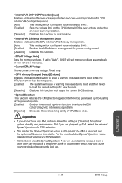
... boot from the BIOS file inside USB flash disk (FAT/ FAT32 format only). ▶ BIOS Boot Function [Disabled] Enables or disables the system to boot form USB flash disk with BIOS file. [Enabled] Enables the system to boot from the BIOS within USB flash disk. [Disabled] Enables the system to boot from the BIOS within ROM on motherboard. *This may cause system unstable, MSI recommend it only for power users. ▶ Select one file to update BIOS Selects a BIOS file in the USB flash disk (NTFS/ FAT 32 format) to update the BIOS...
... boot from the BIOS file inside USB flash disk (FAT/ FAT32 format only). ▶ BIOS Boot Function [Disabled] Enables or disables the system to boot form USB flash disk with BIOS file. [Enabled] Enables the system to boot from the BIOS within USB flash disk. [Disabled] Enables the system to boot from the BIOS within ROM on motherboard. *This may cause system unstable, MSI recommend it only for power users. ▶ Select one file to update BIOS Selects a BIOS file in the USB flash disk (NTFS/ FAT 32 format) to update the BIOS...
User Guide
Page 93
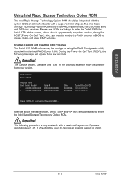
... a newly-built system or if you need to enable the RAID function in system boot-up, during the POST (Power-On Self Test). RAID Volumes None defined. Important The "Device Model", "Serial #" and "Size" in the following procedure is the Intel RAID implementation and provides BIOS and DOS disk services. Creating, Deleting and Resetting RAID Volumes: The Serial ATA RAID volume may be configured using the RAID Configuration utility stored within the Intel RAID Option ROM.
... a newly-built system or if you need to enable the RAID function in system boot-up, during the POST (Power-On Self Test). RAID Volumes None defined. Important The "Device Model", "Serial #" and "Size" in the following procedure is the Intel RAID implementation and provides BIOS and DOS disk services. Creating, Deleting and Resetting RAID Volumes: The Serial ATA RAID volume may be configured using the RAID Configuration utility stored within the Intel RAID Option ROM.
User Guide
Page 102
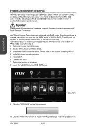
... use a slow virtual disk or depend on the Setup screen. The OS must set the SATA Mode to RAID in order to accelerate the system performance. Reboot and enter the BIOS steup. 2. Insert the MSI DVD into the DVD-ROM drive. Click here 10. Click the "Intel RAID Driver" to enable system acceleration. Which can only work with the advantages of high-speed read/write and non-volatile memory to support Intel® Rapid Storage Technology...
... use a slow virtual disk or depend on the Setup screen. The OS must set the SATA Mode to RAID in order to accelerate the system performance. Reboot and enter the BIOS steup. 2. Insert the MSI DVD into the DVD-ROM drive. Click here 10. Click the "Intel RAID Driver" to enable system acceleration. Which can only work with the advantages of high-speed read/write and non-volatile memory to support Intel® Rapid Storage Technology...


