

User Guide
Page 4
... provide reasonable protection against harmful interference in accordance with the limits for compliance could void the user's authority to operate the equipment. Micro-Star International MS-7528 This device complies with the emission limits.
... provide reasonable protection against harmful interference in accordance with the limits for compliance could void the user's authority to operate the equipment. Micro-Star International MS-7528 This device complies with the emission limits.
User Guide
Page 10
Getting Started Chapter 1 Getting Started Thank you for optimal system efficiency. The G31M3 Series mainboards are based on Intel® G31 & ICH7/ICH7R chipsets for choosing the G31M3 Series (MS-7528 v1.X) Micro-ATX mainboard. Designed to fit the advanced Intel® Core 2 Duo/Quad/Pentium/Celeron LGA775 processor, the G31M3 Series deliver a high performance and professional desktop platform solution. 1-1
Getting Started Chapter 1 Getting Started Thank you for optimal system efficiency. The G31M3 Series mainboards are based on Intel® G31 & ICH7/ICH7R chipsets for choosing the G31M3 Series (MS-7528 v1.X) Micro-ATX mainboard. Designed to fit the advanced Intel® Core 2 Duo/Quad/Pentium/Celeron LGA775 processor, the G31M3 Series deliver a high performance and professional desktop platform solution. 1-1
User Guide
Page 11
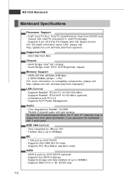
MS-7528 Mainboard Mainboard Specifications Processor Support - m s i. North Bridge: Intel® G31 chipset - DDR2 667/800 SDRAM (4GB Max) - 2 DDR2 DIMMs (240pin / 1.8V) (For more information on ...
MS-7528 Mainboard Mainboard Specifications Processor Support - m s i. North Bridge: Intel® G31 chipset - DDR2 667/800 SDRAM (4GB Max) - 2 DDR2 DIMMs (240pin / 1.8V) (For more information on ...

User Guide
Page 13
MS-7528 Mainboard Mainboard Layout IDE1 CP UFAN 1 Top : mouse B ot tom : ke y boar d Parallel port Bot to m: COM portA VGA port DIMM1 DIMM2 ATX1 T: 1394 port (...) SATA4 JFP2 SY SFA N2 S ATA 2 A LC8 88 PCI 1 CD_IN1 JAUD1 JCOM1 JMicron 381 ( opt i on al) JBAT1 FDD 1 J1394_1(optional) JUSB1 JF P1 JUSB2 G31M3 Series (MS-7528 v1.X) Micro-ATX Mainboard 1-4 SATA3 SATA1
MS-7528 Mainboard Mainboard Layout IDE1 CP UFAN 1 Top : mouse B ot tom : ke y boar d Parallel port Bot to m: COM portA VGA port DIMM1 DIMM2 ATX1 T: 1394 port (...) SATA4 JFP2 SY SFA N2 S ATA 2 A LC8 88 PCI 1 CD_IN1 JAUD1 JCOM1 JMicron 381 ( opt i on al) JBAT1 FDD 1 J1394_1(optional) JUSB1 JF P1 JUSB2 G31M3 Series (MS-7528 v1.X) Micro-ATX Mainboard 1-4 SATA3 SATA1

User Guide
Page 18
... the CPU, make sure the CPU has a cooler attached on it to protect the socket pin. 2. Remove the cap from damage. Confirm if your system. 2. MS-7528 Mainboard CPU & Cooler Installation W hen you install the CPU, always cover it to avoid damaging. 3. The pins of the CPU land side cover depends on...
... the CPU, make sure the CPU has a cooler attached on it to protect the socket pin. 2. Remove the cap from damage. Confirm if your system. 2. MS-7528 Mainboard CPU & Cooler Installation W hen you install the CPU, always cover it to avoid damaging. 3. The pins of the CPU land side cover depends on...

User Guide
Page 20
... rotate the locking switch (refer to the correct direction marked on it) to confirm that the clip-ends are for demonstration of the mainboard. 11. MS-7528 Mainboard 9. Press down to avoid damaging. 3.
... rotate the locking switch (refer to the correct direction marked on it) to confirm that the clip-ends are for demonstration of the mainboard. 11. MS-7528 Mainboard 9. Press down to avoid damaging. 3.

User Guide
Page 22
... is deeply inserted in the right orientation. 2. Then push it in until the golden finger on the center and will automatically close. Volt Notch Important - MS-7528 Mainboard Installing Memory Modules 1. In Dual-Channel mode, make sure that you install memory modules of the DIMM slot will only fit in the DIMM...
... is deeply inserted in the right orientation. 2. Then push it in until the golden finger on the center and will automatically close. Volt Notch Important - MS-7528 Mainboard Installing Memory Modules 1. In Dual-Channel mode, make sure that you install memory modules of the DIMM slot will only fit in the DIMM...

User Guide
Page 24
... (ECP) mode. Serial Port The serial port is for monitor. 1394 Port (optional) The IEEE1394 port on the back panel provides connection to the connector. MS-7528 Mainboard Back Panel Mouse Keyboard Parallel Port 1394 Port (optional) Type A L-In RS-Out LAN L-Out CS-Out Serial Port VGA Port Mouse Parallel Port...
... (ECP) mode. Serial Port The serial port is for monitor. 1394 Port (optional) The IEEE1394 port on the back panel provides connection to the connector. MS-7528 Mainboard Back Panel Mouse Keyboard Parallel Port 1394 Port (optional) Type A L-In RS-Out LAN L-Out CS-Out Serial Port VGA Port Mouse Parallel Port...
User Guide
Page 26
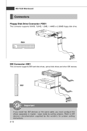
MS-7528 Mainboard Connectors Floppy Disk Drive Connector: FDD1 This connector supports 360KB, 720KB, 1.2MB, 1.44MB or 2.88MB floppy disk drive. IDE1 Important If you install two IDE devices on the same cable, you must configure the drives separately to IDE device's documentation supplied by setting jumpers. Refer to master / slave mode by the vendors for jumper setting instructions. 2-12 FDD1 IDE Connector: IDE1 This connector supports IDE hard disk drives, optical disk drives and other IDE devices.
MS-7528 Mainboard Connectors Floppy Disk Drive Connector: FDD1 This connector supports 360KB, 720KB, 1.2MB, 1.44MB or 2.88MB floppy disk drive. IDE1 Important If you install two IDE devices on the same cable, you must configure the drives separately to IDE device's documentation supplied by setting jumpers. Refer to master / slave mode by the vendors for jumper setting instructions. 2-12 FDD1 IDE Connector: IDE1 This connector supports IDE hard disk drives, optical disk drives and other IDE devices.
User Guide
Page 28
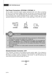
... Dual Core Center utility that the red wire is opened, the chassis intrusion mechanism will automatically control the CPU fan speed according to the +12V; MS-7528 Mainboard Fan Power Connectors: CPUFAN1, SYSFAN1~2 The fan power connectors support system cooling fan with +12V.
... Dual Core Center utility that the red wire is opened, the chassis intrusion mechanism will automatically control the CPU fan speed according to the +12V; MS-7528 Mainboard Fan Power Connectors: CPUFAN1, SYSFAN1~2 The fan power connectors support system cooling fan with +12V.

User Guide
Page 30
... Power Switch high reference pull-up Reset Switch high reference pull-up Power Switch low reference pull-down to the front panel switches and LEDs. MS-7528 Mainboard Front Panel Connectors: JFP1, JFP2 These connectors are for external audio input.
... Power Switch high reference pull-up Reset Switch high reference pull-up Power Switch low reference pull-down to the front panel switches and LEDs. MS-7528 Mainboard Front Panel Connectors: JFP1, JFP2 These connectors are for external audio input.

User Guide
Page 32
MS-7528 Mainboard Front USB Connector: JUSB1 ~ 2 These connectors, compliant with Intel® I/O Connectivity Design Guide, is a 16550A high speed communication port that the pins of VCC ...
MS-7528 Mainboard Front USB Connector: JUSB1 ~ 2 These connectors, compliant with Intel® I/O Connectivity Design Guide, is a 16550A high speed communication port that the pins of VCC ...
User Guide
Page 34
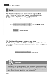
MS-7528 Mainboard Slots PCI (Peripheral Component Interconnect) Express Slots The PCI Express slot supports the PCI Express interface expansion card. The PCI Express x 16 slot supports ...
MS-7528 Mainboard Slots PCI (Peripheral Component Interconnect) Express Slots The PCI Express slot supports the PCI Express interface expansion card. The PCI Express x 16 slot supports ...

User Guide
Page 37
... line appearing after the memory count is usually in this BIOS was released. 3-2 V1.0 refers to the BIOS version. 011708 refers to the customer as MS = all standard customers. Therefore, the description may also restart the system by turning it OFF and On or pressing the RESET button. W hen the... held for better system performance. Press DEL to enter SETUP If the message disappears before you respond and you still wish to enter Setup. MS-7528 Mainboard Entering Setup Power on the screen, press key to enter Setup, restart the system by simultaneously pressing , , and keys.
... line appearing after the memory count is usually in this BIOS was released. 3-2 V1.0 refers to the BIOS version. 011708 refers to the customer as MS = all standard customers. Therefore, the description may also restart the system by turning it OFF and On or pressing the RESET button. W hen the... held for better system performance. Press DEL to enter SETUP If the message disappears before you respond and you still wish to enter Setup. MS-7528 Mainboard Entering Setup Power on the screen, press key to enter Setup, restart the system by simultaneously pressing , , and keys.
User Guide
Page 39
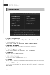
... Use this menu to specify your settings for integrated peripherals. Integrated Peripherals Use this menu to load the default values set the password for BIOS. MS-7528 Mainboard The Main Menu Standard CMOS Features Use this menu to specify your settings for power management. Power Management Setup Use this menu for basic...
... Use this menu to specify your settings for integrated peripherals. Integrated Peripherals Use this menu to load the default values set the password for BIOS. MS-7528 Mainboard The Main Menu Standard CMOS Features Use this menu to specify your settings for power management. Power Management Setup Use this menu for basic...

User Guide
Page 41
.... date The date from Jan. Time (HH:MM :SS) This allows you to set the system to the date that you want in each item. MS-7528 Mainboard Standard CMOS Features The items in Standard CMOS Features Menu includes some basic setup items. Use the arrow keys to highlight the item and...
.... date The date from Jan. Time (HH:MM :SS) This allows you to set the system to the date that you want in each item. MS-7528 Mainboard Standard CMOS Features The items in Standard CMOS Features Menu includes some basic setup items. Use the arrow keys to highlight the item and...
User Guide
Page 43
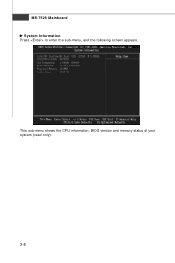
MS-7528 Mainboard System Information Press to enter the sub-menu, and the following screen appears. This sub-menu shows the CPU information, BIOS version and memory status of your system (read only). 3-8
MS-7528 Mainboard System Information Press to enter the sub-menu, and the following screen appears. This sub-menu shows the CPU information, BIOS version and memory status of your system (read only). 3-8
User Guide
Page 45
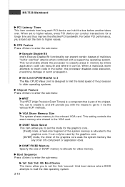
..." attacks when combined with the means to get to allocate for video memory. VGA Share Memory Size The system shares memory to the graphics core. MS-7528 Mainboard PCI Latency Timer This item controls how long each PCI device can execute and where it , and will provide you to set the mode...
..." attacks when combined with the means to get to allocate for video memory. VGA Share Memory Size The system shares memory to the graphics core. MS-7528 Mainboard PCI Latency Timer This item controls how long each PCI device can execute and where it , and will provide you to set the mode...
User Guide
Page 47
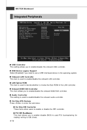
MS-7528 Mainboard Integrated Peripherals USB Controller This setting allows you to enable/disable the onboard IEEE1394 controller. Onboard IEEE1394 Controller This item allows you to enable/...
MS-7528 Mainboard Integrated Peripherals USB Controller This setting allows you to enable/disable the onboard IEEE1394 controller. Onboard IEEE1394 Controller This item allows you to enable/...
User Guide
Page 49
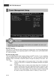
... hardware components turn off to restore the system when a "wake up" event occurs. 3-14 Settings are available only when your BIOS supports S3 sleep mode. MS-7528 Mainboard Power Management Setup Important S3-related functions described in S1(POS) or S3(STR) fashion through the setting of system configuration and open applications...
... hardware components turn off to restore the system when a "wake up" event occurs. 3-14 Settings are available only when your BIOS supports S3 sleep mode. MS-7528 Mainboard Power Management Setup Important S3-related functions described in S1(POS) or S3(STR) fashion through the setting of system configuration and open applications...


