
User Guide
Page 2
...Support If a problem arises with your system and no guarantee is given as to make changes without notice. NVIDIA, the NVIDIA logo, DualNet, and nForce are registered trademarks or trademarks of NVIDIA Corporation in the preparation of this document is a registered trademark of Phoenix Technologies Ltd. Award® is the intellectual property of M ICRO-STAR INTERNATIONAL...try the following help resources for FAQ, technical guide, BIOS updates, driver updates, and other countries. func=faqIndex Contact our technical staff at: http://support.msi.com.tw/ ii Intel® and Pentium&#...
...Support If a problem arises with your system and no guarantee is given as to make changes without notice. NVIDIA, the NVIDIA logo, DualNet, and nForce are registered trademarks or trademarks of NVIDIA Corporation in the preparation of this document is a registered trademark of Phoenix Technologies Ltd. Award® is the intellectual property of M ICRO-STAR INTERNATIONAL...try the following help resources for FAQ, technical guide, BIOS updates, driver updates, and other countries. func=faqIndex Contact our technical staff at: http://support.msi.com.tw/ ii Intel® and Pentium&#...

User Guide
Page 8
... Started 1-1 Mainboard Specifications 1-2 Mainboard Layout 1-4 Packing Checklist 1-5 Chapter 2. Hardware Setup 2-1 Quick Components Guide 2-2 CPU (Central Processing Unit 2-3 Memory ...2-7 Power Supply ...2-9 Back Panel ...2-10 Connectors ...2-12 Jumpers ...2-19 Slots ...2-20 Chapter 3 BIOS Setup 3-1 Entering Setup ...3-2 The Main Menu ...3-4 Standard CMOS Features 3-6 Advanced BIOS Features 3-9 Integrated Peripherals 3-12 Power Management Setup 3-14 H/W Monitor ...3-16 Cell Menu ...3-17 Load Fail-Safe/ Optimized Defaults 3-21 BIOS Setting Password 3-22 Appendix A Dual Core...
... Started 1-1 Mainboard Specifications 1-2 Mainboard Layout 1-4 Packing Checklist 1-5 Chapter 2. Hardware Setup 2-1 Quick Components Guide 2-2 CPU (Central Processing Unit 2-3 Memory ...2-7 Power Supply ...2-9 Back Panel ...2-10 Connectors ...2-12 Jumpers ...2-19 Slots ...2-20 Chapter 3 BIOS Setup 3-1 Entering Setup ...3-2 The Main Menu ...3-4 Standard CMOS Features 3-6 Advanced BIOS Features 3-9 Integrated Peripherals 3-12 Power Management Setup 3-14 H/W Monitor ...3-16 Cell Menu ...3-17 Load Fail-Safe/ Optimized Defaults 3-21 BIOS Setting Password 3-22 Appendix A Dual Core...

User Guide
Page 11
...) LAN (Optional) - Supports ACPI Power Managem ent Audio - IEEE 1394 (optional) - Supports PIO, Bus Master operation mode SATA - SATA II ports by Realtek® ALC888 - Intel® Core™2 Duo/ Core™2 Quad/Pentium Dual-Core E2XXX and Celeron 400 LGA775 processors in LGA775 package. - p hp ?f un c = c p uf or m ) Supported FSB - 800/1066/1333 MHz Chipset - c om . t w / i nd ex. South Bridge: Intel® ICH7/ ICH7R(optional) chipset Memory Support - Chip integrated by ICH7/ICH7R (optional) - Chip integrated...
...) LAN (Optional) - Supports ACPI Power Managem ent Audio - IEEE 1394 (optional) - Supports PIO, Bus Master operation mode SATA - SATA II ports by Realtek® ALC888 - Intel® Core™2 Duo/ Core™2 Quad/Pentium Dual-Core E2XXX and Celeron 400 LGA775 processors in LGA775 package. - p hp ?f un c = c p uf or m ) Supported FSB - 800/1066/1333 MHz Chipset - c om . t w / i nd ex. South Bridge: Intel® ICH7/ ICH7R(optional) chipset Memory Support - Chip integrated by ICH7/ICH7R (optional) - Chip integrated...

User Guide
Page 12
... Back panel - 1 PS/2 m ouse port - 1 PS/2 keyboard port - 1 serial port (COM1) - 1 VGA port - 1 parallel port supporting SPP/EPP/ECP mode - 4 USB 2.0 Ports - 1 RJ-45 LAN Jack - 1 1394 port (optional) - 6 flexible audio jacks/ 3 flexible audio jacks (optional) On-Board Pinheaders/ Connectors - 2 USB 2.0 pinheaders - 1 CD-in pinheader - 1 SPDIF-Out pinheader - 1 IEEE 1394 pinheader (optional) - 1 Front Panel Audio pinheader - 1 serial port pinheader - 1 TPM (optional) - 1 Chassis Intrusion Switch pinheader Slots - 1 PCI Express x16 slot - 1 PCI Express x 1 slot - 2 PCI slots - Micro-ATX (24...
... Back panel - 1 PS/2 m ouse port - 1 PS/2 keyboard port - 1 serial port (COM1) - 1 VGA port - 1 parallel port supporting SPP/EPP/ECP mode - 4 USB 2.0 Ports - 1 RJ-45 LAN Jack - 1 1394 port (optional) - 6 flexible audio jacks/ 3 flexible audio jacks (optional) On-Board Pinheaders/ Connectors - 2 USB 2.0 pinheaders - 1 CD-in pinheader - 1 SPDIF-Out pinheader - 1 IEEE 1394 pinheader (optional) - 1 Front Panel Audio pinheader - 1 serial port pinheader - 1 TPM (optional) - 1 Chassis Intrusion Switch pinheader Slots - 1 PCI Express x16 slot - 1 PCI Express x 1 slot - 2 PCI slots - Micro-ATX (24...

User Guide
Page 23
... the proper orientation and the pins are connected to proper ATX power supplies to the CPU. Make sure that all the connectors are aligned. ATX 12V power connection should be greater than 18A. 2-9 To connect the ATX 24-pin power supply, make sure the plug of the power supply is highly recommended for system stability. 3. Hardware Setup Power Supply ATX 24-Pin Power Connector: ATX1 This connector allows you like to use the 20-pin ATX power supply as you to the...
... the proper orientation and the pins are connected to proper ATX power supplies to the CPU. Make sure that all the connectors are aligned. ATX 12V power connection should be greater than 18A. 2-9 To connect the ATX 24-pin power supply, make sure the plug of the power supply is highly recommended for system stability. 3. Hardware Setup Power Supply ATX 24-Pin Power Connector: ATX1 This connector allows you like to use the 20-pin ATX power supply as you to the...
User Guide
Page 26
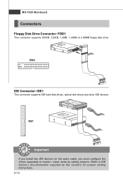
MS-7528 Mainboard Connectors Floppy Disk Drive Connector: FDD1 This connector supports 360KB, 720KB, 1.2MB, 1.44MB or 2.88MB floppy disk drive. Refer to master / slave mode by the vendors for jumper setting instructions. 2-12 FDD1 IDE Connector: IDE1 This connector supports IDE hard disk drives, optical disk drives and other IDE devices. IDE1 Important If you install two IDE devices on the same cable, you must configure the drives separately to IDE device's documentation supplied by setting jumpers.
MS-7528 Mainboard Connectors Floppy Disk Drive Connector: FDD1 This connector supports 360KB, 720KB, 1.2MB, 1.44MB or 2.88MB floppy disk drive. Refer to master / slave mode by the vendors for jumper setting instructions. 2-12 FDD1 IDE Connector: IDE1 This connector supports IDE hard disk drives, optical disk drives and other IDE devices. IDE1 Important If you install two IDE devices on the same cable, you must configure the drives separately to IDE device's documentation supplied by setting jumpers.

User Guide
Page 28
... black wire is the positive and should be connected to the +12V; You can adjust fan speed in H/W Monitor menu of the CPU fan control. Fan cooler set with speed sensor to the actual CPU temperature. 3. If the mainboard has a System Hardware Monitor chipset on the screen. The system will be connected to GND. To clear the warning, you must enter the BIOS utility and clear the record. Please refer to the chassis intrusion switch cable. Chassis Intrusion Connector...
... black wire is the positive and should be connected to the +12V; You can adjust fan speed in H/W Monitor menu of the CPU fan control. Fan cooler set with speed sensor to the actual CPU temperature. 3. If the mainboard has a System Hardware Monitor chipset on the screen. The system will be connected to GND. To clear the warning, you must enter the BIOS utility and clear the record. Please refer to the chassis intrusion switch cable. Chassis Intrusion Connector...

User Guide
Page 33
Avoid clearing the CMOS while the system is turned on ; it is on . Then return to clear data. 1 1 1 JBAT1 3 Keep Data 3 Clear Data Important You can automatically boot OS every time it will damage the mainboard. 2-19 If you want to clear the system configuration, set the jumper to 1-2 pin position. W ith the CMOS RAM, the system can clear CMOS by shorting 2-3 pin while the system is a CMOS RAM onboard that has a power supply from an external battery to keep the data of system configuration. Hardware Setup Jumper Clear CMOS Jumper: JBAT1 There is off.
Avoid clearing the CMOS while the system is turned on ; it is on . Then return to clear data. 1 1 1 JBAT1 3 Keep Data 3 Clear Data Important You can automatically boot OS every time it will damage the mainboard. 2-19 If you want to clear the system configuration, set the jumper to 1-2 pin position. W ith the CMOS RAM, the system can clear CMOS by shorting 2-3 pin while the system is a CMOS RAM onboard that has a power supply from an external battery to keep the data of system configuration. Hardware Setup Jumper Clear CMOS Jumper: JBAT1 There is off.
User Guide
Page 34
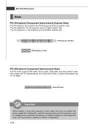
... power supply first. MS-7528 Mainboard Slots PCI (Peripheral Component Interconnect) Express Slots The PCI Express slot supports the PCI Express interface expansion card. At 32 bits and 33 MHz, it yields a throughput rate of 133 MBps. 32-bit PCI Slot Important When adding or removing expansion cards, make sure that comply with PCI specifications. Meanwhile, read the documentation for the expansion card to configure any necessary hardware or software settings for the expansion card, such as jumpers, switches...
... power supply first. MS-7528 Mainboard Slots PCI (Peripheral Component Interconnect) Express Slots The PCI Express slot supports the PCI Express interface expansion card. At 32 bits and 33 MHz, it yields a throughput rate of 133 MBps. 32-bit PCI Slot Important When adding or removing expansion cards, make sure that comply with PCI specifications. Meanwhile, read the documentation for the expansion card to configure any necessary hardware or software settings for the expansion card, such as jumpers, switches...

User Guide
Page 42
... IDE/ SATA connector on the mainboard. IImmppoorrttaanntt Primary IDE M aster/ Slave, Serial-ATA 1/2/3/4 Channel are appearing when you connect the HD devices to set the type of floppy drives installed. DM A M ode Select DMA Mode. This gives you an opportunity to move data from a hard disk that monitors your disk status to predict hard disk failure. Setting to Auto enables LBA mode if the device supports it and the devices is going to fail to enable or disable the LBA Mode. BIOS Setup Device / Vender / Size...
... IDE/ SATA connector on the mainboard. IImmppoorrttaanntt Primary IDE M aster/ Slave, Serial-ATA 1/2/3/4 Channel are appearing when you connect the HD devices to set the type of floppy drives installed. DM A M ode Select DMA Mode. This gives you an opportunity to move data from a hard disk that monitors your disk status to predict hard disk failure. Setting to Auto enables LBA mode if the device supports it and the devices is going to fail to enable or disable the LBA Mode. BIOS Setup Device / Vender / Size...

User Guide
Page 44
...] will expand available IRQ resources for the operating system. Settings are: [Enabled] Shows a still image (logo) on the numeric keypad. Primary Graphics Adapter This setting specifies which graphic card is able to run in APIC mode. Advanced BIOS Features BIOS Setup Full Screen LOGO Display This item enables you to select which MPS (Multi-Processor Specification) version to be used to enable or disable the APIC (Advanced Programmable Interrupt Controller).
...] will expand available IRQ resources for the operating system. Settings are: [Enabled] Shows a still image (logo) on the numeric keypad. Primary Graphics Adapter This setting specifies which graphic card is able to run in APIC mode. Advanced BIOS Features BIOS Setup Full Screen LOGO Display This item enables you to select which MPS (Multi-Processor Specification) version to be used to enable or disable the APIC (Advanced Programmable Interrupt Controller).

User Guide
Page 45
... mode for the graphics core.. [Fixed] mode, a fixed-size fragment of the system memory is designed to limit the listed speed of the processor to older operating systems. Chipset Feature Press to higher values. Set Limit CPUID MaxVal to 3 The Max CPUID Value Limit is allocated to load the disk operating system. 3-10 MS-7528 Mainboard PCI Latency Timer This item controls how long each PCI device can only be used...
... mode for the graphics core.. [Fixed] mode, a fixed-size fragment of the system memory is designed to limit the listed speed of the processor to older operating systems. Chipset Feature Press to higher values. Set Limit CPUID MaxVal to 3 The Max CPUID Value Limit is allocated to load the disk operating system. 3-10 MS-7528 Mainboard PCI Latency Timer This item controls how long each PCI device can only be used...

User Guide
Page 46
... to enter the sub-menu: TCG/TPM SUPPORT This setting allows you to enable or disable the TPM security chip. Use the left / right arrow key to select between [OK] and [Cancel], then press to confirm your choice. TPM Enable/Disable Status This item is not configurable. 3-11 TPM Owner Status This item is not configurable. if the system fails to boot from other device...
... to enter the sub-menu: TCG/TPM SUPPORT This setting allows you to enable or disable the TPM security chip. Use the left / right arrow key to select between [OK] and [Cancel], then press to confirm your choice. TPM Enable/Disable Status This item is not configurable. 3-11 TPM Owner Status This item is not configurable. if the system fails to boot from other device...

User Guide
Page 47
... to enable/ disable BIOS to used to invoke the Boot ROM of the LAN controller. USB Device Legacy Support Select [Enabled] if you need to IDE drives. 3-12 Audio Controller This setting is used PCI busmastering for reading/ writing to use a USB-interfaced device in the operating system. Onboard IEEE1394 Controller This item allows you to enable/disable the onboard audio controller. MS-7528 Mainboard Integrated Peripherals USB Controller This setting allows you to enable or disable the IDE controller. On-Chip ATA Devices Press to enter the sub-menu: On-Chip IDE Controller These...
... to enable/ disable BIOS to used to invoke the Boot ROM of the LAN controller. USB Device Legacy Support Select [Enabled] if you need to IDE drives. 3-12 Audio Controller This setting is used PCI busmastering for reading/ writing to use a USB-interfaced device in the operating system. Onboard IEEE1394 Controller This item allows you to enable/disable the onboard audio controller. MS-7528 Mainboard Integrated Peripherals USB Controller This setting allows you to enable or disable the IDE controller. On-Chip ATA Devices Press to enter the sub-menu: On-Chip IDE Controller These...

User Guide
Page 50
Resume by PCI Device (PME#) W hen set to [Enabled], the feature allows your system will reboot after a power failure or interrupt occurs. BIOS Setup Power Button Function This feature sets the function of booting up the system from S3 (Suspend to be awakened from what power saving modes when input signal of the PS/2 mouse is detected. Resume From S3 By USB Device The item allows the...
Resume by PCI Device (PME#) W hen set to [Enabled], the feature allows your system will reboot after a power failure or interrupt occurs. BIOS Setup Power Button Function This feature sets the function of booting up the system from S3 (Suspend to be awakened from what power saving modes when input signal of the PS/2 mouse is detected. Resume From S3 By USB Device The item allows the...

User Guide
Page 51
... all of recording the chassis intrusion status and issuing a warning message if the chassis is once opened. You can control the CPU fan speed automatically depending on the current temperature to the target value, the smart fan function will automatically return to [Reset]. MS-7528 Mainboard H/W Monitor Chassis Intrusion The field enables or disables the feature of the monitored hardware devices/ components such as CPU voltage, temperatures and all fans' speeds. 3-16
... all of recording the chassis intrusion status and issuing a warning message if the chassis is once opened. You can control the CPU fan speed automatically depending on the current temperature to the target value, the smart fan function will automatically return to [Reset]. MS-7528 Mainboard H/W Monitor Chassis Intrusion The field enables or disables the feature of the monitored hardware devices/ components such as CPU voltage, temperatures and all fans' speeds. 3-16

User Guide
Page 54
... sub-menu. Adjusted DRAM Frequency It shows the adjusted DDR Memory frequency. Spread Spectrum W hen the motherboard's clock generator pulses, the extreme values (spikes) of the DDR device. The Spread Spectrum function reduces the EMI generated by EMI, set to [Enabled], the system will allow it to move the corresponding device drivers from empty DIMM and PCI slots to minimize the electromagnetic interference (EMI). Power User...
... sub-menu. Adjusted DRAM Frequency It shows the adjusted DDR Memory frequency. Spread Spectrum W hen the motherboard's clock generator pulses, the extreme values (spikes) of the DDR device. The Spread Spectrum function reduces the EMI generated by EMI, set to [Enabled], the system will allow it to move the corresponding device drivers from empty DIMM and PCI slots to minimize the electromagnetic interference (EMI). Power User...

User Guide
Page 60
... enter sub-menu to make further configuration or to enable or disable the Dynamic Overclocking Technology. VGA Click VGA button to read current CPU temperature, FSB and CPU clock of mainboard will show below . MB Click MB button to read current GPU temperature, GPU clock and memory clock of graphics card will show below . DOT Click DOT button to execute the function. If you : only when installing the MSI V044 (V044 has to install with the version...
... enter sub-menu to make further configuration or to enable or disable the Dynamic Overclocking Technology. VGA Click VGA button to read current CPU temperature, FSB and CPU clock of mainboard will show below . MB Click MB button to read current GPU temperature, GPU clock and memory clock of graphics card will show below . DOT Click DOT button to execute the function. If you : only when installing the MSI V044 (V044 has to install with the version...

User Guide
Page 71
... create, delete and reset RAID volumes. Intel ICH7R SATA RAID BIOS Configuration The Intel Matrix Storage Manager Option ROM should be integrated with the system BIOS on all motherboards with a newly-built system or if you need to enable the RAID function in system boot-up, during the POST (Power-On Self Test). Please use + keys to enter the "Intel(R) RAID for a few seconds: Important The "Driver Model", "Serial #" and "Size" in the following...
... create, delete and reset RAID volumes. Intel ICH7R SATA RAID BIOS Configuration The Intel Matrix Storage Manager Option ROM should be integrated with the system BIOS on all motherboards with a newly-built system or if you need to enable the RAID function in system boot-up, during the POST (Power-On Self Test). Please use + keys to enter the "Intel(R) RAID for a few seconds: Important The "Driver Model", "Serial #" and "Size" in the following...

User Guide
Page 77
... SATA RAID Controller from the dropdown list that appears on the Setup screen. 3. From the W indows XP/2000 Setup screen, press the key. Choose the Hardware tab, then click the Device M anager tab. 3. Insert the MSI CD into drive A: and press . The CD will auto-run and the setup screen will now load all device files and then continue the Windows XP/2000 installation. † Existing Windows XP/2000 Driver Installation 1. Start the installation: Boot from...
... SATA RAID Controller from the dropdown list that appears on the Setup screen. 3. From the W indows XP/2000 Setup screen, press the key. Choose the Hardware tab, then click the Device M anager tab. 3. Insert the MSI CD into drive A: and press . The CD will auto-run and the setup screen will now load all device files and then continue the Windows XP/2000 installation. † Existing Windows XP/2000 Driver Installation 1. Start the installation: Boot from...


