User Guide
Page 12
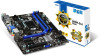
Preface Internal Connectors 1-19 SATA1~6: SATA Connectors 1-19 CPUFAN,SYSFAN1~2: Fan Power Connectors 1-20 JFP1, JFP2: System Panel Connectors 1-21 JUSB1~2: USB 2.0 Expansion Connector 1-22 JUSB3: USB 3.0 Expansion Connector... Serial Port Connector 1-25 Jumper 1-25 JBAT1: Clear CMOS Jumper 1-25 Drivers and Utilities 1-26 Total Installer 1-26 Chapter 2 Quick Installation 2-1 CPU Installation 2-2 Memory Installation 2-4 Motherboard Installation 2-5 Power Connectors Installation 2-7 SATA HDD Installation 2-9 mSATA SSD Installation 2-10 Front Panel Connector Installation 2-11 JFP1...
Preface Internal Connectors 1-19 SATA1~6: SATA Connectors 1-19 CPUFAN,SYSFAN1~2: Fan Power Connectors 1-20 JFP1, JFP2: System Panel Connectors 1-21 JUSB1~2: USB 2.0 Expansion Connector 1-22 JUSB3: USB 3.0 Expansion Connector... Serial Port Connector 1-25 Jumper 1-25 JBAT1: Clear CMOS Jumper 1-25 Drivers and Utilities 1-26 Total Installer 1-26 Chapter 2 Quick Installation 2-1 CPU Installation 2-2 Memory Installation 2-4 Motherboard Installation 2-5 Power Connectors Installation 2-7 SATA HDD Installation 2-9 mSATA SSD Installation 2-10 Front Panel Connector Installation 2-11 JFP1...
User Guide
Page 21
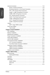
Chapter 1 Connectors Reference Guide Port Name Port Type Back Panel CPU Socket LGA1150 CPU Socket CPUFAN,SYSFAN1~2 Fan Power Connectors DIMM1~4 DDR3 Memory Slots JAUD1 Front Panel Audio Connector JBAT1 Clear CMOS Jumper JCI1 Chassis Intrusion Connector JCOM1 Serial Port Connector JFP1, JFP2 .../s Connectors Page 1-8 1-11 1-20 1-14 1-23 1-25 1-23 1-25 1-21 1-24 1-16 1-24 1-22 1-22 1-17 1-17 1-17 1-19 1-19 For the latest information about CPU, please visit http://www.msi.com/service/cpu-support/ For more information on compatible components, please visit http://www...
Chapter 1 Connectors Reference Guide Port Name Port Type Back Panel CPU Socket LGA1150 CPU Socket CPUFAN,SYSFAN1~2 Fan Power Connectors DIMM1~4 DDR3 Memory Slots JAUD1 Front Panel Audio Connector JBAT1 Clear CMOS Jumper JCI1 Chassis Intrusion Connector JCOM1 Serial Port Connector JFP1, JFP2 .../s Connectors Page 1-8 1-11 1-20 1-14 1-23 1-25 1-23 1-25 1-21 1-24 1-16 1-24 1-22 1-22 1-17 1-17 1-17 1-19 1-19 For the latest information about CPU, please visit http://www.msi.com/service/cpu-support/ For more information on compatible components, please visit http://www...
User Guide
Page 24
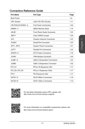
...the system's power supply and unplug the power supply's power cord to protect the CPU from overheating. Before attempting to overclock, please make sure the cooling fans work properly to ensure the safety of the CPU. Notch Notch Chapter 1 Golden triangle is not recommend. Always make sure that ... 1-10 Be sure to apply an even layer of thermal paste (or thermal tape) between the CPU and the heatsink to assist in correctly lining up the CPU for motherboard placement. MSI does not guarantee the damages or risks caused by inadequate operation beyond product specifications is the Pin ...
...the system's power supply and unplug the power supply's power cord to protect the CPU from overheating. Before attempting to overclock, please make sure the cooling fans work properly to ensure the safety of the CPU. Notch Notch Chapter 1 Golden triangle is not recommend. Always make sure that ... 1-10 Be sure to apply an even layer of thermal paste (or thermal tape) between the CPU and the heatsink to assist in correctly lining up the CPU for motherboard placement. MSI does not guarantee the damages or risks caused by inadequate operation beyond product specifications is the Pin ...

User Guide
Page 27
... down the heatsink until the four fasteners get wedged into position a click should be heard. 10. Locate the CPU fan connector on the motherboard with the plastic cap. • If you purchased a separate CPU and heatsink/ cooler, Please refer to ensure that the fastener-ends have been properly locked in the heatsink/ cooler...
... down the heatsink until the four fasteners get wedged into position a click should be heard. 10. Locate the CPU fan connector on the motherboard with the plastic cap. • If you purchased a separate CPU and heatsink/ cooler, Please refer to ensure that the fastener-ends have been properly locked in the heatsink/ cooler...

User Guide
Page 34
... ensure that there are no cables impeding any available system fan connector. The Command Center utility can be installed to automatically control the fan speeds according to the CPU's and system's temperature. • If there are not ...fan with +12V. If the motherboard has a System Hardware Monitor chipset on the motherboard to connect all system fans, adapters are available to connect a fan directly to connect all system fans. Chapter 1 CPUFAN,SYSFAN1~2: Fan Power Connectors The fan power connectors support system cooling fans with a speed sensor to take advantage of the CPU fan...
... ensure that there are no cables impeding any available system fan connector. The Command Center utility can be installed to automatically control the fan speeds according to the CPU's and system's temperature. • If there are not ...fan with +12V. If the motherboard has a System Hardware Monitor chipset on the motherboard to connect all system fans, adapters are available to connect a fan directly to connect all system fans. Chapter 1 CPUFAN,SYSFAN1~2: Fan Power Connectors The fan power connectors support system cooling fans with a speed sensor to take advantage of the CPU fan...
User Guide
Page 57
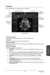
... the motherboard. ▶ Language Allows you to select the language of the BIOS setup. ▶ System information Shows the time, date, CPU name, CPU frequency, DRAM frequency, DRAM capacity and the BIOS version. ▶ BIOS menu selection The following screen is used to set various overclocking profiles... menu provides the way to update BIOS with a USB flash disk. ■ OC PROFILE -This menu is used to set the speeds of fans and monitors voltages of the installed devices on the motherboard. This menu is displayed. Chapter 3 3-3 BIOS Setup It will provide the information of...
... the motherboard. ▶ Language Allows you to select the language of the BIOS setup. ▶ System information Shows the time, date, CPU name, CPU frequency, DRAM frequency, DRAM capacity and the BIOS version. ▶ BIOS menu selection The following screen is used to set various overclocking profiles... menu provides the way to update BIOS with a USB flash disk. ■ OC PROFILE -This menu is used to set the speeds of fans and monitors voltages of the installed devices on the motherboard. This menu is displayed. Chapter 3 3-3 BIOS Setup It will provide the information of...

User Guide
Page 78
... the maximum temperature, the CPU/ system fan will run at the minimum speed. Smart Fan Control automatically controls fan speed depending on the "Fan control field". When the current CPU temperature is under the minimum temperature, the CPU/ system fan will run at the maximum speed. The green shows current CPU/ System fan speed. ▶ Fan control field This motherboard provides...
... the maximum temperature, the CPU/ system fan will run at the minimum speed. Smart Fan Control automatically controls fan speed depending on the "Fan control field". When the current CPU temperature is under the minimum temperature, the CPU/ system fan will run at the maximum speed. The green shows current CPU/ System fan speed. ▶ Fan control field This motherboard provides...

User Guide
Page 79
Slides the arrow symbol to set the maximum fan speed in percentage. ■ e - Click the "Default" button to activate the following items for changing default values. ■ c - Important • The minimum values of CPU, system and memory. Chapter 3 3-25 BIOS Setup a b d c e f ■ a - Slides the ... the default values. Slides the arrow symbol to set the temperatures and fan speeds. Or click the "Cancel" button to abandon all changes and restore to specify the speed. ■ b - Selects a fan you save the changes and reboot the system. ▶ Voltage display ...
Slides the arrow symbol to set the maximum fan speed in percentage. ■ e - Click the "Default" button to activate the following items for changing default values. ■ c - Important • The minimum values of CPU, system and memory. Chapter 3 3-25 BIOS Setup a b d c e f ■ a - Slides the ... the default values. Slides the arrow symbol to set the temperatures and fan speeds. Or click the "Cancel" button to abandon all changes and restore to specify the speed. ■ b - Selects a fan you save the changes and reboot the system. ▶ Voltage display ...


