
User Manual
Page 13
... Connector 32 JTPM1: TPM Module Connector 32 JCOM1: Serial Port Connector 32 CPUFAN1~2,SYSFAN1~3: Fan Connectors 33 JLPT1: Parallel Port Connector 34 JBAT1: Clear CMOS (Reset BIOS) Jumper 34 JCI1: Chassis Intrusion Connector 35 Contents 13
... Connector 32 JTPM1: TPM Module Connector 32 JCOM1: Serial Port Connector 32 CPUFAN1~2,SYSFAN1~3: Fan Connectors 33 JLPT1: Parallel Port Connector 34 JBAT1: Clear CMOS (Reset BIOS) Jumper 34 JCI1: Chassis Intrusion Connector 35 Contents 13
User Manual
Page 14
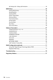
EZ Debug LED: Debug LED indicators 35 BIOS Setup...36 Entering BIOS Setup 36 Resetting BIOS 37 Updating BIOS...37 System Status Menu 38 Advanced Menu 39 Overclocking Menu 46 M-Flash Menu...52 Security Menu...53 Boot Menu...55 Save & Exit Menu 56 Software ...
EZ Debug LED: Debug LED indicators 35 BIOS Setup...36 Entering BIOS Setup 36 Resetting BIOS 37 Updating BIOS...37 System Status Menu 38 Advanced Menu 39 Overclocking Menu 46 M-Flash Menu...52 Security Menu...53 Boot Menu...55 Save & Exit Menu 56 Software ...
User Manual
Page 23
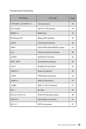
...~2 JTPM1 JUSB1~2 JUSB3 M2_1 PCI_E1~5, PCI1~2 SATA1~6 SE1_21 Port Type Fan Connectors LGA1151 CPU Socket DIMM Slots Debug LED indicators Front Audio Connector Clear CMOS (Reset BIOS) Jumper Chassis Intrusion Connector Serial Port Connector Front Panel Connectors Parallel Port Connector Power Connectors TPM Module Connector USB 2.0 Connectors USB 3.1 Gen1 Connector M.2 Slot PCIe...
...~2 JTPM1 JUSB1~2 JUSB3 M2_1 PCI_E1~5, PCI1~2 SATA1~6 SE1_21 Port Type Fan Connectors LGA1151 CPU Socket DIMM Slots Debug LED indicators Front Audio Connector Clear CMOS (Reset BIOS) Jumper Chassis Intrusion Connector Serial Port Connector Front Panel Connectors Parallel Port Connector Power Connectors TPM Module Connector USB 2.0 Connectors USB 3.1 Gen1 Connector M.2 Slot PCIe...
User Manual
Page 34
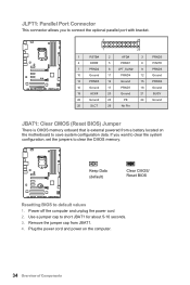
... Ground 17 PRND7 18 Ground 19 ACK# 20 Ground 21 BUSY 22 Ground 23 PE 24 Ground 25 SLCT 26 No Pin JBAT1: Clear CMOS (Reset BIOS) Jumper There is CMOS memory onboard that is external powered from JBAT1. 4. Plug the power cord and power on the motherboard to short JBAT1 for... computer and unplug the power cord 2. Remove the jumper cap from a battery located on the computer. 34 Overview of Components Keep Data (default) Clear CMOS/ Reset BIOS Resetting BIOS to clear the CMOS memory.
... Ground 17 PRND7 18 Ground 19 ACK# 20 Ground 21 BUSY 22 Ground 23 PE 24 Ground 25 SLCT 26 No Pin JBAT1: Clear CMOS (Reset BIOS) Jumper There is CMOS memory onboard that is external powered from JBAT1. 4. Plug the power cord and power on the motherboard to short JBAT1 for... computer and unplug the power cord 2. Remove the jumper cap from a battery located on the computer. 34 Overview of Components Keep Data (default) Clear CMOS/ Reset BIOS Resetting BIOS to clear the CMOS memory.
User Manual
Page 35
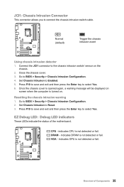
..., a warning message will be displayed on screen when the computer is not detected or fail. VGA - Overview of the motherboard. Resetting the chassis intrusion warning 1. EZ Debug LED: Debug LED indicators These LEDs indicate the status of Components 35 DRAM - JCI1: Chassis... chassis intrusion switch cable. indicates GPU is turned on the chassis. 2. Set Chassis Intrusion to BIOS > Security > Chassis Intrusion Configuration. 4. indicates CPU is not detected or fail. Go to Reset. 3. Connect the JCI1 connector to Enabled. 5. Press F10 to save and exit and then press...
..., a warning message will be displayed on screen when the computer is not detected or fail. VGA - Overview of the motherboard. Resetting the chassis intrusion warning 1. EZ Debug LED: Debug LED indicators These LEDs indicate the status of Components 35 DRAM - JCI1: Chassis... chassis intrusion switch cable. indicates GPU is turned on the chassis. 2. Set Chassis Intrusion to BIOS > Security > Chassis Intrusion Configuration. 4. indicates CPU is not detected or fail. Go to Reset. 3. Connect the JCI1 connector to Enabled. 5. Press F10 to save and exit and then press...

User Manual
Page 36
... for 4 seconds upon bootup. Therefore, the description may vary from the latest BIOS and should always keep the default settings to enter Boot Menu message appears on the screen during the boot process. ●● Use MSI FAST BOOT application. Click on GO2BIOS button and choose OK. Function key Key ... Menu, F11 to avoid possible system damage or failure booting unless you press F10, a confirmation window appears and it F10 Save Change and Reset* F12 to confirm your choice. 36 BIOS Setup Important ●● BIOS items are continuous update for reference only.
... for 4 seconds upon bootup. Therefore, the description may vary from the latest BIOS and should always keep the default settings to enter Boot Menu message appears on the screen during the boot process. ●● Use MSI FAST BOOT application. Click on GO2BIOS button and choose OK. Function key Key ... Menu, F11 to avoid possible system damage or failure booting unless you press F10, a confirmation window appears and it F10 Save Change and Reset* F12 to confirm your choice. 36 BIOS Setup Important ●● BIOS items are continuous update for reference only.
User Manual
Page 37
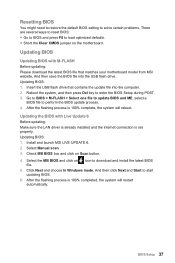
... system will reboot. Install and launch MSI LIVE UPDATE 6. 2. Updating BIOS: 1. Select the MB BIOS and click on Scan button. 4. Check MB BIOS box and click on file. And then click Next and Start to enter the BIOS Setup during POST. 3. Resetting BIOS You might need to restore the default BIOS setting to solve certain problems. There are...
... system will reboot. Install and launch MSI LIVE UPDATE 6. 2. Updating BIOS: 1. Select the MB BIOS and click on Scan button. 4. Check MB BIOS box and click on file. And then click Next and Start to enter the BIOS Setup during POST. 3. Resetting BIOS You might need to restore the default BIOS setting to solve certain problems. There are...

User Manual
Page 54
... equips a chassis intrusion switch. [Enabled] Once the chassis is ready for installed TPM device. If set to Enabled or Disabled. [Disabled] Disables this funcion. 54 BIOS Setup After clearing the message, please return to Auto, BIOS will record and issue a warning message. [Reset] Clear the warning message. This function is opened .
... equips a chassis intrusion switch. [Enabled] Once the chassis is ready for installed TPM device. If set to Enabled or Disabled. [Disabled] Disables this funcion. 54 BIOS Setup After clearing the message, please return to Auto, BIOS will record and issue a warning message. [Reset] Clear the warning message. This function is opened .

User Manual
Page 71
...4 Excellent OK Good 50% Using Intel® Rapid Storage Technology Option ROM First, you are written to create, delete and reset RAID volumes. Create RAID Volume 4. Reset Disks to enter the IRST Option ROM during the POST, the following procedure is only available with a newly-built system or if... you need to set the SATA mode to RAID in excellent performance and good fault tolerance. Select [ESC] - Exit [ENTER] - This results in BIOS to ...
...4 Excellent OK Good 50% Using Intel® Rapid Storage Technology Option ROM First, you are written to create, delete and reset RAID volumes. Create RAID Volume 4. Reset Disks to enter the IRST Option ROM during the POST, the following procedure is only available with a newly-built system or if... you need to set the SATA mode to RAID in excellent performance and good fault tolerance. Select [ESC] - Exit [ENTER] - This results in BIOS to ...
User Manual
Page 76
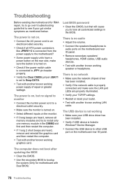
... restart the computer. ●● If 1 long 2 short beeps are properly illuminated. ●● Verify your TCP/IP settings. ●● Restart or reset your router. ●● Test with another known working graphics card. The computer does not boot after updating the...jumper JBAT1 is listed in Windows® Device Manager. ●● Connect the USB device to audio ports on the motherboard rear IO panel. Lost BIOS password ●● Clear the CMOS, but no audio ●● Adjust the volume. ●● Connect the speakers/headphones to other USB port...
... restart the computer. ●● If 1 long 2 short beeps are properly illuminated. ●● Verify your TCP/IP settings. ●● Restart or reset your router. ●● Test with another known working graphics card. The computer does not boot after updating the...jumper JBAT1 is listed in Windows® Device Manager. ●● Connect the USB device to audio ports on the motherboard rear IO panel. Lost BIOS password ●● Clear the CMOS, but no audio ●● Adjust the volume. ●● Connect the speakers/headphones to other USB port...

