
User Manual
Page 13
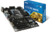
... Quick Start...3 Preparing Tools and Components 3 Installing a Processor 4 Installing DDR4 memory 5 Connecting the Front Panel Header 6 Installing the Motherboard 7 Installing SATA Drives 8 Installing a Graphics Card 9 Connecting Peripheral Devices 10 Connecting the Power Connectors 11 Power On...12 Specifications...15 Block Diagram ...19 Rear I/O Panel...20 LAN Port LED Status Table 20 Realtek HD Audio Manager 20 Overview of Components 22 CPU Socket...24 DIMM Slots...25 PCI_E1~5, PCI1~2: PCIe/ PCI Expansion Slots 26 SATA1~6: SATA 6Gb/s Connectors 27 SE1_21: SATAe Connector 27...
... Quick Start...3 Preparing Tools and Components 3 Installing a Processor 4 Installing DDR4 memory 5 Connecting the Front Panel Header 6 Installing the Motherboard 7 Installing SATA Drives 8 Installing a Graphics Card 9 Connecting Peripheral Devices 10 Connecting the Power Connectors 11 Power On...12 Specifications...15 Block Diagram ...19 Rear I/O Panel...20 LAN Port LED Status Table 20 Realtek HD Audio Manager 20 Overview of Components 22 CPU Socket...24 DIMM Slots...25 PCI_E1~5, PCI1~2: PCIe/ PCI Expansion Slots 26 SATA1~6: SATA 6Gb/s Connectors 27 SE1_21: SATAe Connector 27...
User Manual
Page 14
... LED indicators 35 BIOS Setup...36 Entering BIOS Setup 36 Resetting BIOS 37 Updating BIOS...37 System Status Menu 38 Advanced Menu 39 Overclocking Menu 46 M-Flash Menu...52 Security Menu...53 Boot Menu...55 Save & Exit Menu 56 Software Description 57 Installing Windows® 7/ 8.1/ 10 57 Installing Drivers 57 Installing Utilities 57 COMMAND CENTER 58 LIVE UPDATE 6 62 M-CLOUD...64 RAMDISK...67 NETWORK GENIE 68 Intel® Extreme Tuning Utility 70 RAID Configuration (optional 71 Using Intel® Rapid Storage Technology Option ROM 71 Degraded RAID Array 74 Troubleshooting...
... LED indicators 35 BIOS Setup...36 Entering BIOS Setup 36 Resetting BIOS 37 Updating BIOS...37 System Status Menu 38 Advanced Menu 39 Overclocking Menu 46 M-Flash Menu...52 Security Menu...53 Boot Menu...55 Save & Exit Menu 56 Software Description 57 Installing Windows® 7/ 8.1/ 10 57 Installing Drivers 57 Installing Utilities 57 COMMAND CENTER 58 LIVE UPDATE 6 62 M-CLOUD...64 RAMDISK...67 NETWORK GENIE 68 Intel® Extreme Tuning Utility 70 RAID Configuration (optional 71 Using Intel® Rapid Storage Technology Option ROM 71 Degraded RAID Array 74 Troubleshooting...
User Manual
Page 15
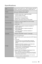
Specifications CPU Chipset Memory Expansion Slots Onboard Graphics Multi-GPU Storage Supports 6th Gen Intel® Core™ i3/i5/i7 processors, and Intel® Pentium® and Celeron® processors for Socket LGA1151 Intel® H170 Chipset (H170A PC MATE) Intel® B150 Chipset (B150 PC MATE) ●● 4x DDR4 memory slots, support up to 64GB ▶▶Supports DDR4 2133 MHz ●● Dual channel memory architecture ●● Supports ECC, un-buffered memory ●● Supports Intel®...
Specifications CPU Chipset Memory Expansion Slots Onboard Graphics Multi-GPU Storage Supports 6th Gen Intel® Core™ i3/i5/i7 processors, and Intel® Pentium® and Celeron® processors for Socket LGA1151 Intel® H170 Chipset (H170A PC MATE) Intel® B150 Chipset (B150 PC MATE) ●● 4x DDR4 memory slots, support up to 64GB ▶▶Supports DDR4 2133 MHz ●● Dual channel memory architecture ●● Supports ECC, un-buffered memory ●● Supports Intel®...
User Manual
Page 16
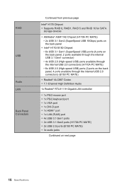
RAID USB Audio LAN Back Panel Connectors Continued from previous page Intel® H170 Chipset ●● Supports RAID 0, RAID1, RAID 5 and RAID 10 for SATA storage devices ●● ASMedia® ASM1142 Chipset (H170A PC MATE) ▶▶2x USB 3.1 Gen2 (SuperSpeed USB 10Gbps) ports on the back panel ●● Intel® H170/ B150 Chipset ▶▶6x USB 3.1 Gen1 (SuperSpeed USB) ports (4 ports on the back panel, 2 ports available through the internal USB 3.1 Gen1 connector) ▶▶4x USB 2.0 (High-speed USB) ports available through...
RAID USB Audio LAN Back Panel Connectors Continued from previous page Intel® H170 Chipset ●● Supports RAID 0, RAID1, RAID 5 and RAID 10 for SATA storage devices ●● ASMedia® ASM1142 Chipset (H170A PC MATE) ▶▶2x USB 3.1 Gen2 (SuperSpeed USB 10Gbps) ports on the back panel ●● Intel® H170/ B150 Chipset ▶▶6x USB 3.1 Gen1 (SuperSpeed USB) ports (4 ports on the back panel, 2 ports available through the internal USB 3.1 Gen1 connector) ▶▶4x USB 2.0 (High-speed USB) ports available through...

User Manual
Page 33
... fan speed that could be noisy. Voltage Mode fan connectors control fan speed by changing voltage. PWM Mode fan connector 1 CPUFAN1 1 Ground 3 Sense 1 CPUFAN2 2 +12V 4 Speed Control Signal Voltage Mode fan connector 1 SYSFAN1/ SYSFAN3 1 Ground 2 3 Sense 4 1 SYSFAN2 Voltage Control NC Controlling the fan speed There are two ways to CPU temperature. One is to a PWM Mode fan connector, the fan speed will be classified as PWM (Pulse Width Modulation) Mode and Voltage Mode. BIOS > Advanced > Hardware Monitor Command Center BIOS Hardware Monitor sub-menu allows...
... fan speed that could be noisy. Voltage Mode fan connectors control fan speed by changing voltage. PWM Mode fan connector 1 CPUFAN1 1 Ground 3 Sense 1 CPUFAN2 2 +12V 4 Speed Control Signal Voltage Mode fan connector 1 SYSFAN1/ SYSFAN3 1 Ground 2 3 Sense 4 1 SYSFAN2 Voltage Control NC Controlling the fan speed There are two ways to CPU temperature. One is to a PWM Mode fan connector, the fan speed will be classified as PWM (Pulse Width Modulation) Mode and Voltage Mode. BIOS > Advanced > Hardware Monitor Command Center BIOS Hardware Monitor sub-menu allows...
User Manual
Page 34
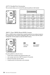
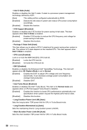
... Ground 21 BUSY 22 Ground 23 PE 24 Ground 25 SLCT 26 No Pin JBAT1: Clear CMOS (Reset BIOS) Jumper There is CMOS memory onboard that is external powered from JBAT1. 4. Plug the power cord and power on the motherboard to save system configuration data. Keep Data (default) Clear CMOS/ Reset BIOS Resetting BIOS to short JBAT1 for about 5-10 seconds. 3. JLPT1: Parallel Port Connector This connector allows you want to clear the system configuration, set the jumpers to clear the CMOS memory.
... Ground 21 BUSY 22 Ground 23 PE 24 Ground 25 SLCT 26 No Pin JBAT1: Clear CMOS (Reset BIOS) Jumper There is CMOS memory onboard that is external powered from JBAT1. 4. Plug the power cord and power on the motherboard to save system configuration data. Keep Data (default) Clear CMOS/ Reset BIOS Resetting BIOS to short JBAT1 for about 5-10 seconds. 3. JLPT1: Parallel Port Connector This connector allows you want to clear the system configuration, set the jumpers to clear the CMOS memory.
User Manual
Page 37
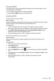
... Start to download and install the latest BIOS 5. Updating BIOS: 1. Resetting BIOS You might need to restore the default BIOS setting to solve certain problems. There are several ways to reset BIOS: ●● Go to BIOS and press F6 to load optimized defaults. ●● Short the Clear CMOS jumper on the motherboard. And then save the BIOS file into the computer. 2. Updating BIOS Updating BIOS with Live Update 6 Before updating: Make sure the LAN driver is already installed and the internet connection...
... Start to download and install the latest BIOS 5. Updating BIOS: 1. Resetting BIOS You might need to restore the default BIOS setting to solve certain problems. There are several ways to reset BIOS: ●● Go to BIOS and press F6 to load optimized defaults. ●● Short the Clear CMOS jumper on the motherboard. And then save the BIOS file into the computer. 2. Updating BIOS Updating BIOS with Live Update 6 Before updating: Make sure the LAN driver is already installed and the internet connection...

User Manual
Page 39
... PCI interface device. [Options: 32, 64, 96, 128, 160, 192, 224, 248 PCI Bus clocks] ▶▶ACPI Settings Sets ACPI parameters of the onboard Power LED. [Dual Color] The power LED turns to another color to indicate the S3 state. [Blinking] The power LED blinks to indicate the S3 state. ▶▶Integrated Peripherals Sets integrated peripherals' parameters, such as LAN, HDD, USB and audio. Press to enter the sub-menu. ▶▶PEG X - Advanced Menu...
... PCI interface device. [Options: 32, 64, 96, 128, 160, 192, 224, 248 PCI Bus clocks] ▶▶ACPI Settings Sets ACPI parameters of the onboard Power LED. [Dual Color] The power LED turns to another color to indicate the S3 state. [Blinking] The power LED blinks to indicate the S3 state. ▶▶Integrated Peripherals Sets integrated peripherals' parameters, such as LAN, HDD, USB and audio. Press to enter the sub-menu. ▶▶PEG X - Advanced Menu...

User Manual
Page 40
..." is enabled. [Enabled] Enables the Ipv6 PXE boot support. [Disabled] Disables the Ipv6 PXE boot support. ▶▶SATA Mode [AHCI Mode] Sets the operation mode of SATA storage device, such as Native Command Queuing (NCQ) and hot-plugging. [RAID Mode] Enables RAID function for optimum system. ▶▶Onboard LAN Controller [Enabled] Enables or disables the onboard LAN controller. ▶▶LAN Option ROM [Disabled] Enables or disables the legacy network Boot Option ROM for optimizing IPv4 / IPv6 function. [Enabled] Enables UEFI network stack. [Disabled] Disables UEFI network...
..." is enabled. [Enabled] Enables the Ipv6 PXE boot support. [Disabled] Disables the Ipv6 PXE boot support. ▶▶SATA Mode [AHCI Mode] Sets the operation mode of SATA storage device, such as Native Command Queuing (NCQ) and hot-plugging. [RAID Mode] Enables RAID function for optimum system. ▶▶Onboard LAN Controller [Enabled] Enables or disables the onboard LAN controller. ▶▶LAN Option ROM [Disabled] Enables or disables the legacy network Boot Option ROM for optimizing IPv4 / IPv6 function. [Enabled] Enables UEFI network stack. [Disabled] Disables UEFI network...
User Manual
Page 41
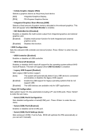
... the primary boot device. [IGD] Integrated Graphics Display. [PEG] PCI-Express Graphics Device. ▶▶Integrated Graphics Share Memory [64M] Selects a fixed amount of serial(COM) port. Press to Auto, BIOS will optimize the IRQ automatically or you can set to enter the submenu. ▶▶Serial (COM) Port0 [Enabled] Enables or disables serial (COM) port. ▶▶Serial (COM) Port0 Settings [Auto] Sets serial port (COM). This item will appear when USB Controller is enabled. ▶▶Legacy USB Support [Enabled] Sets Legacy USB function support. [Auto] The...
... the primary boot device. [IGD] Integrated Graphics Display. [PEG] PCI-Express Graphics Device. ▶▶Integrated Graphics Share Memory [64M] Selects a fixed amount of serial(COM) port. Press to Auto, BIOS will optimize the IRQ automatically or you can set to enter the submenu. ▶▶Serial (COM) Port0 [Enabled] Enables or disables serial (COM) port. ▶▶Serial (COM) Port0 Settings [Auto] Sets serial port (COM). This item will appear when USB Controller is enabled. ▶▶Legacy USB Support [Enabled] Sets Legacy USB function support. [Auto] The...

User Manual
Page 43
... disables for Entering BIOS Setup. Please refer to page 36 for other operating systems. Before enabling this item, make sure all installed devices & utilities (hardware & software) should meet the Windows 8.1/ 10 requirements. [Enabled] The system will disable more devices to boot the system. And the following Fast Boot field will not support S4 & S5 wake up system boot time which is the fastest way to speed up by USB, PCI and PCIe devices. [Disabled] Disables...
... disables for Entering BIOS Setup. Please refer to page 36 for other operating systems. Before enabling this item, make sure all installed devices & utilities (hardware & software) should meet the Windows 8.1/ 10 requirements. [Enabled] The system will disable more devices to boot the system. And the following Fast Boot field will not support S4 & S5 wake up system boot time which is the fastest way to speed up by USB, PCI and PCIe devices. [Disabled] Disables...

User Manual
Page 44
... boot support. [Enabled] Enables the secure boot function and allow you to set wake up events of these items. [OS] The wake up events will only be available when MSI Fast Boot is enabled. [Standard] The system will appear when Secure Boot Mode sets to boot up behaviors for Windows 8.1/ 10. This submenu will automatically load the secure keys from BIOS. [Custom] Allows user to accelerate system boot time. [Disabled] Disables the Fast Boot configuration...
... boot support. [Enabled] Enables the secure boot function and allow you to set wake up events of these items. [OS] The wake up events will only be available when MSI Fast Boot is enabled. [Standard] The system will appear when Secure Boot Mode sets to boot up behaviors for Windows 8.1/ 10. This submenu will automatically load the secure keys from BIOS. [Custom] Allows user to accelerate system boot time. [Disabled] Disables the Fast Boot configuration...

User Manual
Page 45
... fields (using the and to select the date & time settings). ▶▶Resume By PCI/PCI-E Device [Disabled] Enables or disables the system wake up by PCI/ PCI express device. [Enabled] Enables the system to be awakened from the power saving modes when activity or input signal of PCI/ PCIe device is detected. [Disabled] Disables this function. ▶▶Resume by USB Device [Disabled] Disables or enables the system wake up by PS/2 Keyboard to be awakened from sleep state...
... fields (using the and to select the date & time settings). ▶▶Resume By PCI/PCI-E Device [Disabled] Enables or disables the system wake up by PCI/ PCI express device. [Enabled] Enables the system to be awakened from the power saving modes when activity or input signal of PCI/ PCIe device is detected. [Disabled] Disables this function. ▶▶Resume by USB Device [Disabled] Disables or enables the system wake up by PS/2 Keyboard to be awakened from sleep state...
User Manual
Page 46
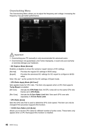
... damage your PC manually is only recommended for advanced users. ●● Overclocking is used to set in X-Core Ratio Limit. ▶▶CPU Ratio [Auto] Sets the CPU ratio that support this function. ▶▶1/2/3/4-Core Ratio Limit [Auto] Allows you to configure in BIOS setup. All CPU cores will run the same CPU ratio that be changed if the processor supports this function is installed. [All Core] Activate the CPU Ratio field. Overclocking Menu The Overclocking Menu allows...
... damage your PC manually is only recommended for advanced users. ●● Overclocking is used to set in X-Core Ratio Limit. ▶▶CPU Ratio [Auto] Sets the CPU ratio that support this function. ▶▶1/2/3/4-Core Ratio Limit [Auto] Allows you to configure in BIOS setup. All CPU cores will run the same CPU ratio that be changed if the processor supports this function is installed. [All Core] Activate the CPU Ratio field. Overclocking Menu The Overclocking Menu allows...
User Manual
Page 47
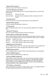
... DRAM Frequency Shows the adjusted DRAM frequency. Please note the overclocking behavior is the overclocking technology by memory module. User can set it occurs, please clear the CMOS data and restore the default settings. (Refer to the Clear CMOS jumper/ button section to clear the CMOS data, and enter the BIOS to load the default settings.) ▶▶CPU Voltages control [Auto] These options allows you can set the memory timing for each/ all memory channel. If it manually. Read-only. ▶▶CPU Ratio Mode [Dynamic Mode...
... DRAM Frequency Shows the adjusted DRAM frequency. Please note the overclocking behavior is the overclocking technology by memory module. User can set it occurs, please clear the CMOS data and restore the default settings. (Refer to the Clear CMOS jumper/ button section to clear the CMOS data, and enter the BIOS to load the default settings.) ▶▶CPU Voltages control [Auto] These options allows you can set the memory timing for each/ all memory channel. If it manually. Read-only. ▶▶CPU Ratio Mode [Dynamic Mode...
User Manual
Page 48
... installed memory. ▶▶DRAM Voltages control [Auto] These options allows you to set the voltages related to PCH. The sub-menu displays the information of installed CPU. The sub-menu shows the key features of installed memory. If set to Auto, BIOS will set these voltages automatically or you can set it manually. ▶▶CPU Memory Changed Detect [Enabled]* Enables or disables the system to issue a warning message during boot when the CPU or memory has been replaced. [Enabled] The system will set these voltages...
... installed memory. ▶▶DRAM Voltages control [Auto] These options allows you to set the voltages related to PCH. The sub-menu displays the information of installed CPU. The sub-menu shows the key features of installed memory. If set to Auto, BIOS will set these voltages automatically or you can set it manually. ▶▶CPU Memory Changed Detect [Enabled]* Enables or disables the system to issue a warning message during boot when the CPU or memory has been replaced. [Enabled] The system will set these voltages...
User Manual
Page 50
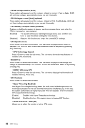
...;Long Duration Maintained (s) [Auto] Sets the maintaining time for Long duration power Limit(W). ▶▶Short Duration Power Limit (W) [Auto] Sets the short duration TDP power limit for power-saving in Turbo Boost mode. 50 BIOS Setup This item will be configured automatically by ACPI. [Auto] This setting will appear when OC Explore Mode is idle. C-state is a processor power management technology defined by BIOS. [Enabled] Detects the idle state of C-state depend on the installed CPU...
...;Long Duration Maintained (s) [Auto] Sets the maintaining time for Long duration power Limit(W). ▶▶Short Duration Power Limit (W) [Auto] Sets the short duration TDP power limit for power-saving in Turbo Boost mode. 50 BIOS Setup This item will be configured automatically by ACPI. [Auto] This setting will appear when OC Explore Mode is idle. C-state is a processor power management technology defined by BIOS. [Enabled] Detects the idle state of C-state depend on the installed CPU...

User Manual
Page 57
.... For Windows 7, access the BIOS menu Advanced > Windows OS Configuration > Windows 7 Installation and set the item to finish. 8. Start up your computer in your optical drive from CD or DVD... The installer will automatically appear and it will prompt you to the leftmost USB port when installing Windows® 7. 5. The installer will find and list all necessary drivers. 4. Click Utilities tab. 4. Click OK button to enabled, save changes and restart. Software Description 57 Software Description Installing Windows®...
.... For Windows 7, access the BIOS menu Advanced > Windows OS Configuration > Windows 7 Installation and set the item to finish. 8. Start up your computer in your optical drive from CD or DVD... The installer will automatically appear and it will prompt you to the leftmost USB port when installing Windows® 7. 5. The installer will find and list all necessary drivers. 4. Click Utilities tab. 4. Click OK button to enabled, save changes and restart. Software Description 57 Software Description Installing Windows®...
User Manual
Page 76
... monitor is properly connected and make sure the button is turned on the motherboard rear IO panel. ●● Remove secondary speakers/ headphones, HDMI cables, USB audio devices. ●● Test with another known working power supply of equal or greater wattage. The computer does not boot after updating the BIOS ●● Clear the CMOS. ●● Use the secondary BIOS to bootup the system (Only for RMA repair, try to install only one memory...
... monitor is properly connected and make sure the button is turned on the motherboard rear IO panel. ●● Remove secondary speakers/ headphones, HDMI cables, USB audio devices. ●● Test with another known working power supply of equal or greater wattage. The computer does not boot after updating the BIOS ●● Clear the CMOS. ●● Use the secondary BIOS to bootup the system (Only for RMA repair, try to install only one memory...
User Manual
Page 80
...Version 2.2, 2015/09, update release for technical guide, BIOS updates, driver updates, and other information: http://www.msi.com ●● Register your place of Micro-Star Int'l Co.,Ltd. Technical Support If a problem... be obtained from the user guide, please contact your product at: http://register.msi.com Trademark Recognition All product names used in the preparation of ...changes without notice. Alternatively, please try the following help resources for further guidance. ●● Visit the MSI website for PCB 2.X. 80 Regulatory Notices We take every care in this manual...
...Version 2.2, 2015/09, update release for technical guide, BIOS updates, driver updates, and other information: http://www.msi.com ●● Register your place of Micro-Star Int'l Co.,Ltd. Technical Support If a problem... be obtained from the user guide, please contact your product at: http://register.msi.com Trademark Recognition All product names used in the preparation of ...changes without notice. Alternatively, please try the following help resources for further guidance. ●● Visit the MSI website for PCB 2.X. 80 Regulatory Notices We take every care in this manual...


