
User Guide
Page 11
... SATA4 DIMM1 DIMM2 SYSFAN1 JPWR1 SATA3 SATA6 SATA5 SATA2 11 The A88XM-E35/ A78M-E35/ A55M-E35 Series motherboards are based on AMD A88X/ A78/ A55 chipset for choosing the A88XM-E35/ A78M-E35/ A55M-E35 Series (MS-7721 v6.X) Micro-ATX motherboard. English English Thank you for optimal system efficiency. Layout Top : mouse... Bottom: USB3.0 ports JCOM1 JTPM1 SYSFAN2 T:Line-In M:Line- Designed to fit the advanced AMD FM2+/ FM processor, the A88XME35/ A78M-E35/ A55M-E35 Series motherboards deliver a high performance and professional desktop platform solution.
... SATA4 DIMM1 DIMM2 SYSFAN1 JPWR1 SATA3 SATA6 SATA5 SATA2 11 The A88XM-E35/ A78M-E35/ A55M-E35 Series motherboards are based on AMD A88X/ A78/ A55 chipset for choosing the A88XM-E35/ A78M-E35/ A55M-E35 Series (MS-7721 v6.X) Micro-ATX motherboard. English English Thank you for optimal system efficiency. Layout Top : mouse... Bottom: USB3.0 ports JCOM1 JTPM1 SYSFAN2 T:Line-In M:Line- Designed to fit the advanced AMD FM2+/ FM processor, the A88XME35/ A78M-E35/ A55M-E35 Series motherboards deliver a high performance and professional desktop platform solution.
User Guide
Page 12
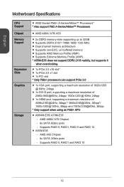
English Motherboard Specifications CPU Support Chipset Memory Support Expansion Slots Graphics Storage ■ AMD Socket FM2+ A-Series/Athlon™ Processors* * Also support FM2 A-Series/Athlon™ Processors &#..., supporting a maximum resolution of 4096x2160@24Hz, 36bpp*/ 3840x2160@30Hz, 36bpp*/ 1920x1200@120Hz, 36bpp and 1920x1200@60Hz, 36bpp * Only support when using an FM2+ APU ■ A88XM-E35/ A78M-E35 - AMD A55 Chipset - 6x SATA 3Gb/s ports - AMD A88X/ A78 Chipset - 6x SATA 6Gb/s ports - Supports RAID 0, RAID1 and RAID 10 12...
English Motherboard Specifications CPU Support Chipset Memory Support Expansion Slots Graphics Storage ■ AMD Socket FM2+ A-Series/Athlon™ Processors* * Also support FM2 A-Series/Athlon™ Processors &#..., supporting a maximum resolution of 4096x2160@24Hz, 36bpp*/ 3840x2160@30Hz, 36bpp*/ 1920x1200@120Hz, 36bpp and 1920x1200@60Hz, 36bpp * Only support when using an FM2+ APU ■ A88XM-E35/ A78M-E35 - AMD A55 Chipset - 6x SATA 3Gb/s ports - AMD A88X/ A78 Chipset - 6x SATA 6Gb/s ports - Supports RAID 0, RAID1 and RAID 10 12...

User Guide
Page 16
Make sure to raise the lever up to ensure correct APU and heatsink installation. The APU can damage both the APU and the motherboard. 1. Pull the lever sideways away from the socket. Follow the steps below to a 90-degree angle. 2. Look for the gold arrow of the APU to ... pins should point as shown in the correct orientation. 3. The gold arrow should be completely embedded into the socket and close the lever with your motherboard. 4. An APU heatsink is likely to your fingers pressing tightly on top of the APU. As the APU is necessary to install a APU heatsink. Press...
Make sure to raise the lever up to ensure correct APU and heatsink installation. The APU can damage both the APU and the motherboard. 1. Pull the lever sideways away from the socket. Follow the steps below to a 90-degree angle. 2. Look for the gold arrow of the APU to ... pins should point as shown in the correct orientation. 3. The gold arrow should be completely embedded into the socket and close the lever with your motherboard. 4. An APU heatsink is likely to your fingers pressing tightly on top of the APU. As the APU is necessary to install a APU heatsink. Press...

User Guide
Page 17
... that the APU cooler has formed a tight seal with the APU before booting your system. • Please refer to the APU fan connector on the motherboard. Then press down the lever. 9. Important • While disconnecting the Safety Hook from the fixed bolt, it . 8. English 5. Fasten down the other end of the... APU Fan cable to the documentation in the APU cooler package for more details about APU cooler installation. 17 Position the cooling set on the motherboard. 6.
... that the APU cooler has formed a tight seal with the APU before booting your system. • Please refer to the APU fan connector on the motherboard. Then press down the lever. 9. Important • While disconnecting the Safety Hook from the fixed bolt, it . 8. English 5. Fasten down the other end of the... APU Fan cable to the documentation in the APU cooler package for more details about APU cooler installation. 17 Position the cooling set on the motherboard. 6.

User Guide
Page 19
English Internal Connectors JPWR1~2: ATX Power Connectors These connectors allow you to ensure stable operation of the motherboard. JCOM1: Serial Port Connector This connector is a 16550A high speed communication port that all the power cables are securely connected to a proper ATX ...power supply to connect an ATX power supply. http://youtu.be hooked on the motherboard's power connector. If done correctly, the clip on the power cable should be /gkDYyR_83I4 1.+2J3.+3.P33.G4VW.3.r+5VoR.5uG6Vn1.r7+do.5uG8Vn.rP9do....
English Internal Connectors JPWR1~2: ATX Power Connectors These connectors allow you to ensure stable operation of the motherboard. JCOM1: Serial Port Connector This connector is a 16550A high speed communication port that all the power cables are securely connected to a proper ATX ...power supply to connect an ATX power supply. http://youtu.be hooked on the motherboard's power connector. If done correctly, the clip on the power cable should be /gkDYyR_83I4 1.+2J3.+3.P33.G4VW.3.r+5VoR.5uG6Vn1.r7+do.5uG8Vn.rP9do....
User Guide
Page 20
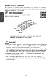
http://youtu.be/RZsMpqxythc SATA4 SATA5 SATA6 SATA1 SATA2 SATA3 A88XM-E35/ A78M-E35 - Such devices include disk drives (HDD), solid state drives (SSD), and optical drives (CD / DVD / Blu-Ray). However, it is a high-speed ... is recommended that large SATA devices, such as HDDs, SSDs, and optical drives, be screwed down into the case. Each connector can connect to the motherboard for further installation instructions. • Please do not fold the SATA cable at a 90-degree angle.
http://youtu.be/RZsMpqxythc SATA4 SATA5 SATA6 SATA1 SATA2 SATA3 A88XM-E35/ A78M-E35 - Such devices include disk drives (HDD), solid state drives (SSD), and optical drives (CD / DVD / Blu-Ray). However, it is a high-speed ... is recommended that large SATA devices, such as HDDs, SSDs, and optical drives, be screwed down into the case. Each connector can connect to the motherboard for further installation instructions. • Please do not fold the SATA cable at a 90-degree angle.

User Guide
Page 21
... the record. 2.C1.IGNTroRuUnd CPUFAN,SYSFAN1~2: Fan Power Connectors The fan power connectors support system cooling fans with liner mode. If the motherboard has a System Hardware Monitor chipset on-board, you must use a specially designed fan with a speed sensor to the power supply directly.... Some system fans may not connect to the motherboard and will instead connect to take advantage of the CPU fan control. CPUFAN/ SYSFAN1 4.3S.pS2e.e+e1n1.dsG2CerVoounntrdol SYSFAN2 3.N2.o+1U1.G2srVeound ...
... the record. 2.C1.IGNTroRuUnd CPUFAN,SYSFAN1~2: Fan Power Connectors The fan power connectors support system cooling fans with liner mode. If the motherboard has a System Hardware Monitor chipset on-board, you must use a specially designed fan with a speed sensor to the power supply directly.... Some system fans may not connect to the motherboard and will instead connect to take advantage of the CPU fan control. CPUFAN/ SYSFAN1 4.3S.pS2e.e+e1n1.dsG2CerVoounntrdol SYSFAN2 3.N2.o+1U1.G2srVeound ...

User Guide
Page 22
... video to learn how to the front panel switches and LEDs. Please use the optional M-Connector to simplify installation. http://youtu.be plugged into the motherboard. When installing the front panel connectors, please use the diagrams above and the writing on your computer case. 2.G4r.oN6uC.Mn8d.1INC0o.DHPeeitnaedctPiohnone Detection 1.M3...
... video to learn how to the front panel switches and LEDs. Please use the optional M-Connector to simplify installation. http://youtu.be plugged into the motherboard. When installing the front panel connectors, please use the diagrams above and the writing on your computer case. 2.G4r.oN6uC.Mn8d.1INC0o.DHPeeitnaedctPiohnone Detection 1.M3...
User Guide
Page 25
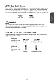
... clear the CMOS RAM. 1 Keep Data 1 Clear Data Important You can automatically boot into the operating system (OS) every time it will damage the motherboard. Do not clear the CMOS RAM while the system is turned on because it is on . Afterwards, open the jumper . If you want to clear ...
... clear the CMOS RAM. 1 Keep Data 1 Clear Data Important You can automatically boot into the operating system (OS) every time it will damage the motherboard. Do not clear the CMOS RAM while the system is turned on because it is on . Afterwards, open the jumper . If you want to clear ...
User Guide
Page 27
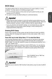
...or pressing the RESET button. Entering BIOS Setup Power on "MSI Fast Boot" utility screen. You can click the "GO2BIOS" tab on "MSI Fast Boot" utility screen or press the physical "GO2BIOS" button (optional) on the motherboard to enable the system going to enter the BIOS setup. Select... the "Restore Defaults" and press in normal conditions. MSI additionally provides two methods to BIOS setup directly at next boot. Click "GO2BIOS"...
...or pressing the RESET button. Entering BIOS Setup Power on "MSI Fast Boot" utility screen. You can click the "GO2BIOS" tab on "MSI Fast Boot" utility screen or press the physical "GO2BIOS" button (optional) on the motherboard to enable the system going to enter the BIOS setup. Select... the "Restore Defaults" and press in normal conditions. MSI additionally provides two methods to BIOS setup directly at next boot. Click "GO2BIOS"...


