
User Guide
Page 11
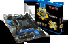
Designed to fit the advanced AMD FM2+/ FM processor, the A88XME35/ A78M-E35/ A55M-E35 Series motherboards deliver a high performance and professional desktop platform solution. Out B:MIC-Int PCI_E1 JCI1 JAUD1 BAT1 PCI_E2 PCI1 JBAT1 JUSB_PW1 JLPT1 JUSB2 JUSB1 JUSB3 JFP1 JFP2 ... Top: VGA Port Bottom: DVI-D Port HDMI port JUSB_PW2 Top: LAN Jack Bottom: USB3.0 ports JCOM1 JTPM1 SYSFAN2 T:Line-In M:Line- The A88XM-E35/ A78M-E35/ A55M-E35 Series motherboards are based on AMD A88X/ A78/ A55 chipset for choosing the A88XM-E35/ A78M-E35/ A55M-E35 Series (MS-7721 v6.X) Micro-ATX...
Designed to fit the advanced AMD FM2+/ FM processor, the A88XME35/ A78M-E35/ A55M-E35 Series motherboards deliver a high performance and professional desktop platform solution. Out B:MIC-Int PCI_E1 JCI1 JAUD1 BAT1 PCI_E2 PCI1 JBAT1 JUSB_PW1 JLPT1 JUSB2 JUSB1 JUSB3 JFP1 JFP2 ... Top: VGA Port Bottom: DVI-D Port HDMI port JUSB_PW2 Top: LAN Jack Bottom: USB3.0 ports JCOM1 JTPM1 SYSFAN2 T:Line-In M:Line- The A88XM-E35/ A78M-E35/ A55M-E35 Series motherboards are based on AMD A88X/ A78/ A55 chipset for choosing the A88XM-E35/ A78M-E35/ A55M-E35 Series (MS-7721 v6.X) Micro-ATX...
User Guide
Page 12
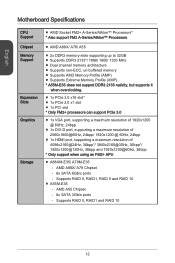
... - Supports RAID 0, RAID1 and RAID 10 12 Supports RAID 0, RAID1, RAID 5 and RAID 10 ■ A55M-E35 - AMD A55 Chipset - 6x SATA 3Gb/s ports - English Motherboard Specifications CPU Support Chipset Memory Support Expansion Slots Graphics Storage ■ AMD Socket FM2+ A-Series/Athlon™ Processors* * Also support FM2 A-Series/Athlon™ Processors..., supporting a maximum resolution of 4096x2160@24Hz, 36bpp*/ 3840x2160@30Hz, 36bpp*/ 1920x1200@120Hz, 36bpp and 1920x1200@60Hz, 36bpp * Only support when using an FM2+ APU ■ A88XM-E35/ A78M-E35 -
... - Supports RAID 0, RAID1 and RAID 10 12 Supports RAID 0, RAID1, RAID 5 and RAID 10 ■ A55M-E35 - AMD A55 Chipset - 6x SATA 3Gb/s ports - English Motherboard Specifications CPU Support Chipset Memory Support Expansion Slots Graphics Storage ■ AMD Socket FM2+ A-Series/Athlon™ Processors* * Also support FM2 A-Series/Athlon™ Processors..., supporting a maximum resolution of 4096x2160@24Hz, 36bpp*/ 3840x2160@30Hz, 36bpp*/ 1920x1200@120Hz, 36bpp and 1920x1200@60Hz, 36bpp * Only support when using an FM2+ APU ■ A88XM-E35/ A78M-E35 -

User Guide
Page 16
... a APU heatsink. Press the APU down firmly into the socket and can not be completely embedded into the socket and close the lever with your motherboard. 4. The APU can damage both the APU and the motherboard. 1. An APU heatsink is properly and completely embedded into the socket. 16
... a APU heatsink. Press the APU down firmly into the socket and can not be completely embedded into the socket and close the lever with your motherboard. 4. The APU can damage both the APU and the motherboard. 1. An APU heatsink is properly and completely embedded into the socket. 16

User Guide
Page 17
... cable to fasten the cooling set onto the retention mechanism. Fasten down the other end of the clip to the APU fan connector on the motherboard. 6. Important • While disconnecting the Safety Hook from the fixed bolt, it . 8. Hook one end of the retention mechanism. English 5. Position the cooling set on...
... cable to fasten the cooling set onto the retention mechanism. Fasten down the other end of the clip to the APU fan connector on the motherboard. 6. Important • While disconnecting the Safety Hook from the fixed bolt, it . 8. Hook one end of the retention mechanism. English 5. Position the cooling set on...

User Guide
Page 19
... 16550A high speed communication port that all the power cables are securely connected to a proper ATX power supply to ensure stable operation of the motherboard. http://youtu.be hooked on the power cable should be /gkDYyR_83I4 1.+2J3.+3.P33.G4VW.3.r+5VoR.5uG6Vn1.r7+do.5uG8Vn.rP9do.Wu51nV0R1d.S1+O1B.1+K2211... Internal Connectors JPWR1~2: ATX Power Connectors These connectors allow you to install power supply connectors. If done correctly, the clip on the motherboard's power connector. You can attach a serial device. 2.S4I.ND6T.DR8S1.C0RT.NSo Pin 1.D3.CS5DO.G7Ur.RTo9uT.RnSdI 19
... 16550A high speed communication port that all the power cables are securely connected to a proper ATX power supply to ensure stable operation of the motherboard. http://youtu.be hooked on the power cable should be /gkDYyR_83I4 1.+2J3.+3.P33.G4VW.3.r+5VoR.5uG6Vn1.r7+do.5uG8Vn.rP9do.Wu51nV0R1d.S1+O1B.1+K2211... Internal Connectors JPWR1~2: ATX Power Connectors These connectors allow you to install power supply connectors. If done correctly, the clip on the motherboard's power connector. You can attach a serial device. 2.S4I.ND6T.DR8S1.C0RT.NSo Pin 1.D3.CS5DO.G7Ur.RTo9uT.RnSdI 19
User Guide
Page 20
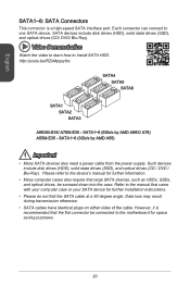
... include disk drives (HDD), solid state drives (SSD), and optical drives (CD / DVD / Blu-Ray). Video Demonstration Watch the video to learn how to the motherboard for further installation instructions. • Please do not fold the SATA cable at a 90-degree angle. Data loss may result during transmission otherwise. • SATA... cable. However, it is a high-speed SATA interface port. Refer to the manual that the flat connector be /RZsMpqxythc SATA4 SATA5 SATA6 SATA1 SATA2 SATA3 A88XM-E35/ A78M-E35 -
... include disk drives (HDD), solid state drives (SSD), and optical drives (CD / DVD / Blu-Ray). Video Demonstration Watch the video to learn how to the motherboard for further installation instructions. • Please do not fold the SATA cable at a 90-degree angle. Data loss may result during transmission otherwise. • SATA... cable. However, it is a high-speed SATA interface port. Refer to the manual that the flat connector be /RZsMpqxythc SATA4 SATA5 SATA6 SATA1 SATA2 SATA3 A88XM-E35/ A78M-E35 -

User Guide
Page 21
... are available to connect a fan directly to a power supply. • Before first boot up, ensure that there are not enough ports on the motherboard to connect all system fans. A system fan can be activated. The Command Center utility can be plugged into any fan blades. 21 If the... motherboard has a System Hardware Monitor chipset on screen. The system will record this intrusion and a warning message will flash on -board, you must use a...
... are available to connect a fan directly to a power supply. • Before first boot up, ensure that there are not enough ports on the motherboard to connect all system fans. A system fan can be activated. The Command Center utility can be plugged into any fan blades. 21 If the... motherboard has a System Hardware Monitor chipset on screen. The system will record this intrusion and a warning message will flash on -board, you must use a...

User Guide
Page 22
http://youtu.be plugged into the motherboard. Video Demonstration Watch the video to learn how to Install front panel connectors. Please use the optional M-Connector to simplify installation. When installing the front ...
http://youtu.be plugged into the motherboard. Video Demonstration Watch the video to learn how to Install front panel connectors. Please use the optional M-Connector to simplify installation. When installing the front ...
User Guide
Page 25
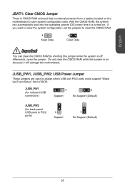
... CMOS RAM. 1 Keep Data 1 Clear Data Important You can automatically boot into the operating system (OS) every time it will damage the motherboard. JUSB_PW1, JUSB_PW2: USB Power Jumper These jumpers are used to save system configuration data. Afterwards, open the jumper . Do not clear the... CMOS RAM while the system is external powered from a battery located on the motherboard to assign which USB and PS/2 ports could support "Wake Up Event Setup" field of BIOS. JUSB_PW1 (for onboard USB connectors) 1 Support ...
... CMOS RAM. 1 Keep Data 1 Clear Data Important You can automatically boot into the operating system (OS) every time it will damage the motherboard. JUSB_PW1, JUSB_PW2: USB Power Jumper These jumpers are used to save system configuration data. Afterwards, open the jumper . Do not clear the... CMOS RAM while the system is external powered from a battery located on the motherboard to assign which USB and PS/2 ports could support "Wake Up Event Setup" field of BIOS. JUSB_PW1 (for onboard USB connectors) 1 Support ...
User Guide
Page 27
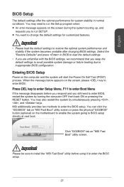
... the BIOS setup. English BIOS Setup The default settings offer the optimal performance for customized features. You can click the "GO2BIOS" tab on "MSI Fast Boot" utility screen or press the physical "GO2BIOS" button (optional) on the screen during the system booting up, and requests you to... system by simultaneously pressing , , and keys. Important Please be sure to install the "MSI Fast Boot" utility before you respond and you still need to run the Setup program when: ■ An error message appears on the motherboard to enable the system going to enter the BIOS setup. 27
... the BIOS setup. English BIOS Setup The default settings offer the optimal performance for customized features. You can click the "GO2BIOS" tab on "MSI Fast Boot" utility screen or press the physical "GO2BIOS" button (optional) on the screen during the system booting up, and requests you to... system by simultaneously pressing , , and keys. Important Please be sure to install the "MSI Fast Boot" utility before you respond and you still need to run the Setup program when: ■ An error message appears on the motherboard to enable the system going to enter the BIOS setup. 27


