

User Guide
Page 2
... arises with your system and no guarantee is given as to make changes without notice. Our products are registered trademarks of AMD Corporation. Visit the MSI website for further guidance. Intel® and Pentium® are registered trademarks of International Business Machines Corporation. PS/2 and OS®/2 are registered ...property of M ICRO-STAR INTERNATIONAL. Award® is a registered trademark of Microsoft Corporation. Alternatively, please try the following help resources for FAQ, technical guide, BIOS updates, driver updates, and other countries.
... arises with your system and no guarantee is given as to make changes without notice. Our products are registered trademarks of AMD Corporation. Visit the MSI website for further guidance. Intel® and Pentium® are registered trademarks of International Business Machines Corporation. PS/2 and OS®/2 are registered ...property of M ICRO-STAR INTERNATIONAL. Award® is a registered trademark of Microsoft Corporation. Alternatively, please try the following help resources for FAQ, technical guide, BIOS updates, driver updates, and other countries.

User Guide
Page 9
Clear CMOS Jumper: JBAT1 2-20 Slots ...2-22 PCI Express Slots 2-21 PCI (Peripheral Component Interconnect) Slots 2-22 PCI Interrupt Request Routing 2-22 Chapter 3. BIOS Setup 3-1 Entering Setup ...3-2 Control Keys 3-3 Getting Help 3-3 General Help
Clear CMOS Jumper: JBAT1 2-20 Slots ...2-22 PCI Express Slots 2-21 PCI (Peripheral Component Interconnect) Slots 2-22 PCI Interrupt Request Routing 2-22 Chapter 3. BIOS Setup 3-1 Entering Setup ...3-2 Control Keys 3-3 Getting Help 3-3 General Help

User Guide
Page 16
... a "sorry" message is a tool used to detect and update your BIOS/drivers/VGA BIOS/VGA Driver/Utility online so that you need to the "Live Update Guide" under the "Manual" Tab. 1-7 After the installation, the "MSI Live Update 3" icon (as shown on the right) will appear: Several...use the function, you don't need to start the update process. Live Driver - Click the desired button to install the "MSI Live Update 3" application. Updates the VGA BIOS online. Getting Started Live Update The Live Update 3™ is displayed. Updates the drivers online. Updates the utilities online.
... a "sorry" message is a tool used to detect and update your BIOS/drivers/VGA BIOS/VGA Driver/Utility online so that you need to the "Live Update Guide" under the "Manual" Tab. 1-7 After the installation, the "MSI Live Update 3" icon (as shown on the right) will appear: Several...use the function, you don't need to start the update process. Live Driver - Click the desired button to install the "MSI Live Update 3" application. Updates the VGA BIOS online. Getting Started Live Update The Live Update 3™ is displayed. Updates the drivers online. Updates the utilities online.

User Guide
Page 22
... that the clip-ends are correctly inserted. Whenever CPU is not installed, always protect your CPU socket pin with the plastic cap covered (shown in BIOS (Chapter 3) for the CPU temperature. 2.
... that the clip-ends are correctly inserted. Whenever CPU is not installed, always protect your CPU socket pin with the plastic cap covered (shown in BIOS (Chapter 3) for the CPU temperature. 2.

User Guide
Page 31
..., always take advantage of the CPU fan c on -board, you must use a specially designed fan with +12V. To clear the warning, you must enter the BIOS utility and clear the record. If the mainboard has a System Hardware Monitor chipset on tr ol . Hardware Setup Fan Power Connectors: CPUFAN1, SYSFAN1, PWRFAN1 The...
..., always take advantage of the CPU fan c on -board, you must use a specially designed fan with +12V. To clear the warning, you must enter the BIOS utility and clear the record. If the mainboard has a System Hardware Monitor chipset on tr ol . Hardware Setup Fan Power Connectors: CPUFAN1, SYSFAN1, PWRFAN1 The...

User Guide
Page 35
... Transmit Data Data Terminal Ready Ground Data Set Ready Request To Send Clear To Send Ring Indicate 2-19 You must configure the setting through the BIOS setup to use the IR function.
... Transmit Data Data Terminal Ready Ground Data Set Ready Request To Send Clear To Send Ring Indicate 2-19 You must configure the setting through the BIOS setup to use the IR function.
User Guide
Page 37
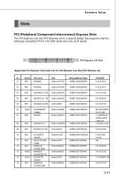
... SDRAM TD128E/128B 13 ASUS EN6600LE Geforce 6600LE 256MB,DDR SDRAM /SILENCER/TD 14 ASUS EAX700/TD RadeonX700 256MB,DDR SDRAM /256M/A 15 MSI NX6600LE- Hardware Setup Slots PCI (Peripheral Component Interconnect) Express Slots The PCI Express Lite slot (PCI Express x4) is a special design ...Radeon X800Pro 128MB, DDR SDRAN 09 MSI MS-8981Ver:100 Geforce6200 128MB, DDR SDRAN 10 MSI RX1300Pro - PCI Express x16 Slot Supported PCI Express VGA Card List for PCI Express Lite Slot (PCI Express x4) No. Geforce 6600LE 128MB,DDR SDRAM TD128E(128B VGA BIOS 4.36.20.38.12 4.34...
... SDRAM TD128E/128B 13 ASUS EN6600LE Geforce 6600LE 256MB,DDR SDRAM /SILENCER/TD 14 ASUS EAX700/TD RadeonX700 256MB,DDR SDRAM /256M/A 15 MSI NX6600LE- Hardware Setup Slots PCI (Peripheral Component Interconnect) Express Slots The PCI Express Lite slot (PCI Express x4) is a special design ...Radeon X800Pro 128MB, DDR SDRAN 09 MSI MS-8981Ver:100 Geforce6200 128MB, DDR SDRAN 10 MSI RX1300Pro - PCI Express x16 Slot Supported PCI Express VGA Card List for PCI Express Lite Slot (PCI Express x4) No. Geforce 6600LE 128MB,DDR SDRAM TD128E(128B VGA BIOS 4.36.20.38.12 4.34...

User Guide
Page 38
... and 33 MHz, it yields a throughput rate of interrupt request line and pronounced I-R-Q, are typically connected to the PCI bus pins as jumpers, switches or BIOS configuration.
... and 33 MHz, it yields a throughput rate of interrupt request line and pronounced I-R-Q, are typically connected to the PCI bus pins as jumpers, switches or BIOS configuration.

User Guide
Page 39
Chapter 3 BIOS Setup BIOS Setup This chapter provides information on the BIOS Setup program and allows you to run the Setup program when: ² An error message appears on the screen during the system booting up, and requests you to change the default settings for optimum use. You may need to run SETUP. ² You want to configure the system for customized features. 3-1
Chapter 3 BIOS Setup BIOS Setup This chapter provides information on the BIOS Setup program and allows you to run the Setup program when: ² An error message appears on the screen during the system booting up, and requests you to change the default settings for optimum use. You may need to run SETUP. ² You want to configure the system for customized features. 3-1

User Guide
Page 40
... the system by turning it OFF and On or pressing the RESET button. It is the BIOS version. Upon boot-up, the 1st line appearing after the memory count is usually in this BIOS was released. 3-2 MS-7267 Mainboard Entering Setup Power on the screen, press key to enter... performance. The items under continuous update for reference only. 2. V1.0 refers to the BIOS version. 030106 refers to the date this chapter are under each BIOS category described in the format: A7267IMS V1.0 030106 where: 1st digit refers to BIOS maker as A = AMI, W = AWARD, and P = PHOENIX. 2nd - 5th digit ...
... the system by turning it OFF and On or pressing the RESET button. It is the BIOS version. Upon boot-up, the 1st line appearing after the memory count is usually in this BIOS was released. 3-2 MS-7267 Mainboard Entering Setup Power on the screen, press key to enter... performance. The items under continuous update for reference only. 2. V1.0 refers to the BIOS version. 030106 refers to the date this chapter are under each BIOS category described in the format: A7267IMS V1.0 030106 where: 1st digit refers to BIOS maker as A = AMI, W = AWARD, and P = PHOENIX. 2nd - 5th digit ...

User Guide
Page 41
... and move from field to field within a sub-menu. You can use and the possible selections for a field parameter. General Help The BIOS setup program provides a General Help screen. BIOS Setup Control Keys Enter> Move to the previous item Move to the next item Move to the item in the right hand...
... and move from field to field within a sub-menu. You can use and the possible selections for a field parameter. General Help The BIOS setup program provides a General Help screen. BIOS Setup Control Keys Enter> Move to the previous item Move to the next item Move to the item in the right hand...

User Guide
Page 42
Advanced BIOS Features Use this menu to change the values in the chipset registers and optimize your settings for power management. PCI/PNP Resource Management This entry ...
Advanced BIOS Features Use this menu to change the values in the chipset registers and optimize your settings for power management. PCI/PNP Resource Management This entry ...

User Guide
Page 43
Exit Without Saving Abandon all changes and exit setup. 3-5 BIOS Setting Password Use this menu to load the default values set the password for optimal performance of the mainboard. Save Changes & Exit Save changes to set by the mainboard manufacturer specifically for BIOS. BIOS Setup Load Optimized Defaults Use this menu to CMOS and exit setup.
Exit Without Saving Abandon all changes and exit setup. 3-5 BIOS Setting Password Use this menu to load the default values set the password for optimal performance of the mainboard. Save Changes & Exit Save changes to set by the mainboard manufacturer specifically for BIOS. BIOS Setup Load Optimized Defaults Use this menu to CMOS and exit setup.

User Guide
Page 44
month The month from Sun to Sat, determined by BIOS. MS-7267 Mainboard Standard CMOS Features System Date (MM:DD:YY) This allows you to set the system time that you want (usually the current ...
month The month from Sun to Sat, determined by BIOS. MS-7267 Mainboard Standard CMOS Features System Date (MM:DD:YY) This allows you to set the system time that you want (usually the current ...

User Guide
Page 45
... options: [Auto], [Disabled], [UDMA0], [UDMA1], [UDMA2], [UDMA3], [UDMA4], [UDMA5]. This gives you to activate the 32bit data transfer to enhance the IDE hard disk performance. BIOS Setup Ty pe This item allows you to activate the S.M.A.R.T. (Self-Monitoring Analysis & Reporting Technology) capability for the hard disks. Setting to enhance the hard...
... options: [Auto], [Disabled], [UDMA0], [UDMA1], [UDMA2], [UDMA3], [UDMA4], [UDMA5]. This gives you to activate the 32bit data transfer to enhance the IDE hard disk performance. BIOS Setup Ty pe This item allows you to activate the S.M.A.R.T. (Self-Monitoring Analysis & Reporting Technology) capability for the hard disks. Setting to enhance the hard...

User Guide
Page 46
... are: [No Errors] [All, But Keyboard] The system doesn't stop for a keyboard error. Type, Version, Build Date, System M emory The items show the CPU information, BIOS version and memory status of floppy drives installed. MS-7267 Mainboard Floppy A This item allows you to set the type of your system (read only). 3-8
... are: [No Errors] [All, But Keyboard] The system doesn't stop for a keyboard error. Type, Version, Build Date, System M emory The items show the CPU information, BIOS version and memory status of floppy drives installed. MS-7267 Mainboard Floppy A This item allows you to set the type of your system (read only). 3-8

User Guide
Page 47
W hen you choose [No], you cannot run the OS/2® operating system with DRAM larger than 64MB. CPU Configuration Press to run the OS/2® operating system with DRAM larger than 64MB. But it will skip some check items. Setting options: [Enabled], [Disabled]. Boot to OS/2 This allows you to enter the sub-menu, and the following screen appears. 3-9 Advanced BIOS Features BIOS Setup Quick Boot Setting the item to [Enabled] allows the system to boot within 5 seconds since it is possible if you choose [Yes].
W hen you choose [No], you cannot run the OS/2® operating system with DRAM larger than 64MB. CPU Configuration Press to run the OS/2® operating system with DRAM larger than 64MB. But it will skip some check items. Setting options: [Enabled], [Disabled]. Boot to OS/2 This allows you to enter the sub-menu, and the following screen appears. 3-9 Advanced BIOS Features BIOS Setup Quick Boot Setting the item to [Enabled] allows the system to boot within 5 seconds since it is possible if you choose [Yes].

User Guide
Page 49
... the PCI Express L0s and L1 link power s t at es . 3-11 PCI Express Configuration Press to enter the sub-menu, and the following screen appears. BIOS Setup M PS Configuration Press to enter the sub-menu, and the following screen appears. To find out which MPS (Multi-Processor Specification) version to be...
... the PCI Express L0s and L1 link power s t at es . 3-11 PCI Express Configuration Press to enter the sub-menu, and the following screen appears. BIOS Setup M PS Configuration Press to enter the sub-menu, and the following screen appears. To find out which MPS (Multi-Processor Specification) version to be...
User Guide
Page 50
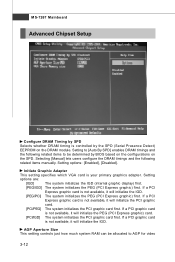
... can be determined by the SPD (Serial Presence Detect) EEPROM on the SPD. Initiate Graphic Adapter This setting specifies which VGA card is controlled by BIOS based on the configurations on the DRAM module. If a PCI graphic card is not available, it will initialize the PEG (PCI Express graphic) card. [PCI...
... can be determined by the SPD (Serial Presence Detect) EEPROM on the SPD. Initiate Graphic Adapter This setting specifies which VGA card is controlled by BIOS based on the configurations on the DRAM module. If a PCI graphic card is not available, it will initialize the PEG (PCI Express graphic) card. [PCI...

User Guide
Page 51
BIOS Setup purposes. The aperture is a portion of the PCI memory address range dedicated to the onboard VGA card. VGA Share Memory size The system shares memory to graphics memory address space. This setting controls the exact memory size shared to the AGP without any translation. Host cycles that hit the aperture range are forwarded to the VGA card. 3-13
BIOS Setup purposes. The aperture is a portion of the PCI memory address range dedicated to the onboard VGA card. VGA Share Memory size The system shares memory to graphics memory address space. This setting controls the exact memory size shared to the AGP without any translation. Host cycles that hit the aperture range are forwarded to the VGA card. 3-13


