User Guide
Page 2
Manual Rev: 1.0 Release Date: May 2004 FCC-B Radio Frequency Interference Statement This equipment has been tested and found to comply with the limits for compliance could void the user's authority to operate the equipment. Notice 1 The changes or modifications not expressly approved by the party responsible for a class B digital device, pursuant to part 15 of the FCC Rules. Micro-Star International MS-7058 This device complies with Part 15 of the FCC rules. Operation of this device must accept any , must be required to comply with the instruction manual, may cause harmful ...
Manual Rev: 1.0 Release Date: May 2004 FCC-B Radio Frequency Interference Statement This equipment has been tested and found to comply with the limits for compliance could void the user's authority to operate the equipment. Notice 1 The changes or modifications not expressly approved by the party responsible for a class B digital device, pursuant to part 15 of the FCC Rules. Micro-Star International MS-7058 This device complies with Part 15 of the FCC rules. Operation of this device must accept any , must be required to comply with the instruction manual, may cause harmful ...

User Guide
Page 3
... IEEE 1394 connectors Date May 2004 June 2004 July 2004 iii Revision History Revision V1.0 V1.1 V1.2 Revision History First release for PCB 1.X with Intel 915P/G & ICH6/ICH6R First release of multi-language Version Add the description of Microsoft Corporation. Microsoft is a registered trademark of NVIDIA Corporation in the United States...
... IEEE 1394 connectors Date May 2004 June 2004 July 2004 iii Revision History Revision V1.0 V1.1 V1.2 Revision History First release for PCB 1.X with Intel 915P/G & ICH6/ICH6R First release of multi-language Version Add the description of Microsoft Corporation. Microsoft is a registered trademark of NVIDIA Corporation in the United States...
User Guide
Page 4
... & FAQ site for further guidance. com.tw/program/service/faq/faq/esc_faq_list.php h Contact our technical staff at: support@msi.com.tw Safety Instructions 1. Always read the safety instructions carefully. 2. Always Unplug the Power Cord before setting it may damage the ... The equipment has obvious sign of the following help resources for technical guide, BIOS updates, driver updates, and other information: http://www.msi.com.tw & http://www.msi. h Liquid has penetrated into the opening that people can be obtained from the user's manual, please contact your place of the power...
... & FAQ site for further guidance. com.tw/program/service/faq/faq/esc_faq_list.php h Contact our technical staff at: support@msi.com.tw Safety Instructions 1. Always read the safety instructions carefully. 2. Always Unplug the Power Cord before setting it may damage the ... The equipment has obvious sign of the following help resources for technical guide, BIOS updates, driver updates, and other information: http://www.msi.com.tw & http://www.msi. h Liquid has penetrated into the opening that people can be obtained from the user's manual, please contact your place of the power...
User Guide
Page 5
... 2-3 Introduction to LGA 775 CPU 2-3 CPU & Cooler Installation 2-4 Memory ...2-7 Introduction to DDR2 SDRAM 2-7 Memory Module Population Rules 2-8 Installing DDR2 Modules 2-8 Power Supply ...2-9 ATX 24-Pin Power Connector: ATX1 2-9 ATX 12V Power Connector: JPW1 2-9 Back Panel ...2-10 Mouse/Keyboard Connector 2-10 VGA Connector (Optional 2-10 Serial Port Connector 2-11 USB Connectors 2-11 LAN...
... 2-3 Introduction to LGA 775 CPU 2-3 CPU & Cooler Installation 2-4 Memory ...2-7 Introduction to DDR2 SDRAM 2-7 Memory Module Population Rules 2-8 Installing DDR2 Modules 2-8 Power Supply ...2-9 ATX 24-Pin Power Connector: ATX1 2-9 ATX 12V Power Connector: JPW1 2-9 Back Panel ...2-10 Mouse/Keyboard Connector 2-10 VGA Connector (Optional 2-10 Serial Port Connector 2-11 USB Connectors 2-11 LAN...

User Guide
Page 6
BIOS Setup 3-1 Entering Setup ...3-3 Selecting the First Boot Device 3-2 Control Keys 3-3 Getting Help 3-3 Main Menu 3-3 Default Settings 3-3 The Main Menu ...3-4 Standard CMOS Features 3-6 Advanced BIOS Features 3-8 Advanced Chipset Features 3-10 Integrated Peripherals 3-11 Power Management Features 3-14 PNP/PCI Configurations 3-17 H/W Monitor ...3-19 Cell Menu ...3-21 BIOS Setting Password 3-25 Load Fail-Safe/Optimized Defaults 3-26 Chapter 4. Introduction to DigiCell 4-1 Main ...4-2 Introduction 4-2 H/W Diagnostic ...4-4 Communication ...4-5 Software Access Point 4-6 vi...
BIOS Setup 3-1 Entering Setup ...3-3 Selecting the First Boot Device 3-2 Control Keys 3-3 Getting Help 3-3 Main Menu 3-3 Default Settings 3-3 The Main Menu ...3-4 Standard CMOS Features 3-6 Advanced BIOS Features 3-8 Advanced Chipset Features 3-10 Integrated Peripherals 3-11 Power Management Features 3-14 PNP/PCI Configurations 3-17 H/W Monitor ...3-19 Cell Menu ...3-21 BIOS Setting Password 3-25 Load Fail-Safe/Optimized Defaults 3-26 Chapter 4. Introduction to DigiCell 4-1 Main ...4-2 Introduction 4-2 H/W Diagnostic ...4-4 Communication ...4-5 Software Access Point 4-6 vi...
User Guide
Page 7
Terminology 4-6 Access Point Mode 4-7 WLAN Card Mode 4-8 Live Update ...4-9 MEGASTICK ...4-10 Basic Function 4-10 Non-Unicode programs supported 4-12 Core Center (for Pentium 4 CPU 4-14 Left-wing: Current system status 4-15 Right-wing: PC hardware status during real time operation 4-15 Audio Speaker Setting 4-16 Power on Agent 4-18 Power On 4-18 Power Off / Restart 4-19 Start With 4-19 Auto Login 4-20 Chapter 5. Introduction to Intel ICH6R SATA RAID 5-1 BIOS Configuration 5-2 Using the Intel RAID Option ROM 5-2 Installing Software 5-8 Install Driver in Windows XP / 2000 5-8...
Terminology 4-6 Access Point Mode 4-7 WLAN Card Mode 4-8 Live Update ...4-9 MEGASTICK ...4-10 Basic Function 4-10 Non-Unicode programs supported 4-12 Core Center (for Pentium 4 CPU 4-14 Left-wing: Current system status 4-15 Right-wing: PC hardware status during real time operation 4-15 Audio Speaker Setting 4-16 Power on Agent 4-18 Power On 4-18 Power Off / Restart 4-19 Start With 4-19 Auto Login 4-20 Chapter 5. Introduction to Intel ICH6R SATA RAID 5-1 BIOS Configuration 5-2 Using the Intel RAID Option ROM 5-2 Installing Software 5-8 Install Driver in Windows XP / 2000 5-8...
User Guide
Page 8
Introduction to CMI9880L Audio Codec 7-1 Installing the Audio Codec Driver 7-2 Software Configuration 7-3 Main Setting 7-3 Smart Jack 7-7 Multi-Stream Function Support & Mixer 7-8 Effect ...7-11 Information 7-11 viii Rebuild Broken RAID 0/0+1 Array 6-12 Installing Software 6-14 Install Driver in Windows 2000/XP 6-14 Installation of VIA IDE RAID Utility 6-15 Using VIA RAID Tool 6-18 Chapter 7.
Introduction to CMI9880L Audio Codec 7-1 Installing the Audio Codec Driver 7-2 Software Configuration 7-3 Main Setting 7-3 Smart Jack 7-7 Multi-Stream Function Support & Mixer 7-8 Effect ...7-11 Information 7-11 viii Rebuild Broken RAID 0/0+1 Array 6-12 Installing Software 6-14 Install Driver in Windows 2000/XP 6-14 Installation of VIA IDE RAID Utility 6-15 Using VIA RAID Tool 6-18 Chapter 7.

User Guide
Page 9
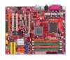
The 915P/G Combo mainboard is based on Intel® 915P/G and Intel® ICH6/ICH6R chipset for choosing the 915P/G Combo (MS-7058) v1.X ATX mainboard. Getting Started Chapter 1. Getting Started Getting Started Thank you for optimal system efficiency. Designed to fit the advanced Intel® Pentium Prescott LGA775 processor, the 915P/G Combo mainboard delivers a high performance and professional desktop platform solution. 1-1
The 915P/G Combo mainboard is based on Intel® 915P/G and Intel® ICH6/ICH6R chipset for choosing the 915P/G Combo (MS-7058) v1.X ATX mainboard. Getting Started Chapter 1. Getting Started Getting Started Thank you for optimal system efficiency. Designed to fit the advanced Intel® Pentium Prescott LGA775 processor, the 915P/G Combo mainboard delivers a high performance and professional desktop platform solution. 1-1
User Guide
Page 10
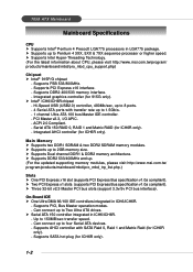
... ATX Mainboard Mainboard Specifications CPU h Supports Intel® Pentium 4 Prescott LGA775 processors in ICH6/ICH6R. - h Supports Intel Hyper-Threading Technology. (For the latest information about CPU, please visit http://www.msi.com.tw/program/ products/mainboard/mbd/pro_mbd_cpu_support.php) Chipset h Intel® 915P/G... Bus Master operation modes. - h Supports up . (For the updated supporting memory modules, please visit http://www.msi.com.tw/ program/products/mainboard/mbd/pro_mbd_trp_list.php.) Slots h One PCI Express x16 slot (supports PCI Express Bus specification v1.0a ...
... ATX Mainboard Mainboard Specifications CPU h Supports Intel® Pentium 4 Prescott LGA775 processors in ICH6/ICH6R. - h Supports Intel Hyper-Threading Technology. (For the latest information about CPU, please visit http://www.msi.com.tw/program/ products/mainboard/mbd/pro_mbd_cpu_support.php) Chipset h Intel® 915P/G... Bus Master operation modes. - h Supports up . (For the updated supporting memory modules, please visit http://www.msi.com.tw/ program/products/mainboard/mbd/pro_mbd_trp_list.php.) Slots h One PCI Express x16 slot (supports PCI Express Bus specification v1.0a ...
User Guide
Page 11
... - 8 USB ports (Rear * 4/ Front * 4) - 1 RJ-45 LAN jack (Optional) LAN (Optional) h Realtek® 8100C / 8110S (Optional) - PCI Express bus Spec 1.0a compliant. - Mounting and Dimension h ATX Form Factor: 24.4 cm (W) x 30.5 cm (L) h 9 mounting holes 1-3 Compliance with 360K, 720K, 1.2M, 1.44M and 2.88Mbytes - 1 serial port - 1 VGA port (for 8100S only). - Audio h Azalia...
... - 8 USB ports (Rear * 4/ Front * 4) - 1 RJ-45 LAN jack (Optional) LAN (Optional) h Realtek® 8100C / 8110S (Optional) - PCI Express bus Spec 1.0a compliant. - Mounting and Dimension h ATX Form Factor: 24.4 cm (W) x 30.5 cm (L) h 9 mounting holes 1-3 Compliance with 360K, 720K, 1.2M, 1.44M and 2.88Mbytes - 1 serial port - 1 VGA port (for 8100S only). - Audio h Azalia...

User Guide
Page 12
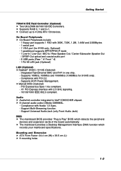
... 3 J1394_2 (Optional) JUSB1 B AT T + SATA2 SATA4 SATA1 SATA3 IDE1 J B AT 1 ICH6/ ICH6R S YS FAN 1 VIA VT6410 IDE 2 IDE 3 JUSB2 JDB1 JFP2 JFP1 ATX1 915P/G Combo (MS-7058) v1.X ATX Mainboard 1-4 7058 ATX Mainboard Mainboard Layout W in bo nd W 83 627 TH F Top : mouse Bottom: keyboard Top : Parallel Port Bottom: COM A VGA port (Optional) C P U FA...
... 3 J1394_2 (Optional) JUSB1 B AT T + SATA2 SATA4 SATA1 SATA3 IDE1 J B AT 1 ICH6/ ICH6R S YS FAN 1 VIA VT6410 IDE 2 IDE 3 JUSB2 JDB1 JFP2 JFP1 ATX1 915P/G Combo (MS-7058) v1.X ATX Mainboard 1-4 7058 ATX Mainboard Mainboard Layout W in bo nd W 83 627 TH F Top : mouse Bottom: keyboard Top : Parallel Port Bottom: COM A VGA port (Optional) C P U FA...
User Guide
Page 13
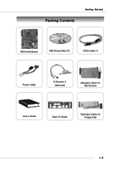
Packing Contents Getting Started MSI motherboard MSI Driver/Utility CD SATA Cable *2 Power Cable D-Bracket 2 (Optional) Standard Cable for IDE Devices User's Guide Back IO Shield Standard Cable for Floppy Disk 1-5
Packing Contents Getting Started MSI motherboard MSI Driver/Utility CD SATA Cable *2 Power Cable D-Bracket 2 (Optional) Standard Cable for IDE Devices User's Guide Back IO Shield Standard Cable for Floppy Disk 1-5

User Guide
Page 14
Also, it provides the instructions on the mainboard. Hardware Setup Chapter 2. Hardware Setup Hardware Setup This chapter tells you how to install the CPU, memory modules, and expansion cards, as well as how to setup the jumpers on connecting the peripheral devices, such as the mouse, keyboard, etc. While doing the installation, be careful in holding the components and follow the installation procedures. 2-1
Also, it provides the instructions on the mainboard. Hardware Setup Chapter 2. Hardware Setup Hardware Setup This chapter tells you how to install the CPU, memory modules, and expansion cards, as well as how to setup the jumpers on connecting the peripheral devices, such as the mouse, keyboard, etc. While doing the installation, be careful in holding the components and follow the installation procedures. 2-1
User Guide
Page 16
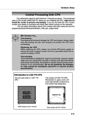
Hardware Setup Central Processing Unit: CPU The mainboard supports Intel® Pentium 4 Prescott processor. Overclocking This motherboard is the Pin 1 indicator 2-3 However, please make sure your dealer to ensure the safety of CPU. We do not have the CPU ...attempt to support overclocking. For the latest information about CPU, please visit http://www.msi.com.tw/ program/products/mainboard/mbd/pro_mbd_cpu_support.php. Replacing the CPU While replacing the CPU, always turn off the ATX power supply or unplug the power supply's power cord from overheating. When you do ...
Hardware Setup Central Processing Unit: CPU The mainboard supports Intel® Pentium 4 Prescott processor. Overclocking This motherboard is the Pin 1 indicator 2-3 However, please make sure your dealer to ensure the safety of CPU. We do not have the CPU ...attempt to support overclocking. For the latest information about CPU, please visit http://www.msi.com.tw/ program/products/mainboard/mbd/pro_mbd_cpu_support.php. Replacing the CPU While replacing the CPU, always turn off the ATX power supply or unplug the power supply's power cord from overheating. When you do ...
User Guide
Page 17
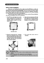
...for the same direction as the CPU (Pin 1 indicator, the red triangle is in the rightbottom corner. 2. land side cover 3. MS-7058 ATX Mainboard CPU & Cooler Installation When you do not forget to apply some silicon heat transfer compound on CPU before turning on the computer. Follow ...Clip, and use your CPU packing. 2-4 The CPU has a land side cover on your 4 fingers to push the CPU Clip down ) together. 4. MSI Reminds You... 1. Take out the accompanying CPU Clip and rotate it to install the CPU & cooler correctly. Meanwhile, do not have the cooler, contact your...
...for the same direction as the CPU (Pin 1 indicator, the red triangle is in the rightbottom corner. 2. land side cover 3. MS-7058 ATX Mainboard CPU & Cooler Installation When you do not forget to apply some silicon heat transfer compound on CPU before turning on the computer. Follow ...Clip, and use your CPU packing. 2-4 The CPU has a land side cover on your 4 fingers to push the CPU Clip down ) together. 4. MSI Reminds You... 1. Take out the accompanying CPU Clip and rotate it to install the CPU & cooler correctly. Meanwhile, do not have the cooler, contact your...

User Guide
Page 18
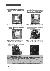
Correctly align the red triangle of CPU clip with the CPU chamfer, the red arrow with the left-side socket edge, and the red spot to protect the contact from lever hinge side (as the arrow shows). 7. Remove the cap from damage. The pins of the socket. 10. Lift the load lever up the load lever. 8. Put the whole module onto the CPU socket. 2-5 The CPU has a plastic cap on it to protect the socket pin. 6. Hardware Setup 5. Before you have installed the CPU, always cover it to the hook of socket reveal. Then lift up and open the load plate. 9.
Correctly align the red triangle of CPU clip with the CPU chamfer, the red arrow with the left-side socket edge, and the red spot to protect the contact from lever hinge side (as the arrow shows). 7. Remove the cap from damage. The pins of the socket. 10. Lift the load lever up the load lever. 8. Put the whole module onto the CPU socket. 2-5 The CPU has a plastic cap on it to protect the socket pin. 6. Hardware Setup 5. Before you have installed the CPU, always cover it to the hook of socket reveal. Then lift up and open the load plate. 9.
User Guide
Page 19
... plate onto the package. 13. Push down the load lever lightly onto the load plate, and then secure the lever with 2 fingers. locking switch MSI Reminds You... 1. Please note that the clip-ends are correctly inserted. Align the holes on it) to avoid damaging. 3. Press the four hooks ...for details) for the CPU temperature. 2. Check the information in PC Health Status of H/W Monitor in Figure 1) to lock the hooks. 16. MS-7058 ATX Mainboard 11. Push down to confirm that the mating/unmating durability of the mainboard. 15. Visually inspect if the CPU is seated well into the...
... plate onto the package. 13. Push down the load lever lightly onto the load plate, and then secure the lever with 2 fingers. locking switch MSI Reminds You... 1. Please note that the clip-ends are correctly inserted. Align the holes on it) to avoid damaging. 3. Press the four hooks ...for details) for the CPU temperature. 2. Check the information in PC Health Status of H/W Monitor in Figure 1) to lock the hooks. 16. MS-7058 ATX Mainboard 11. Push down to confirm that the mating/unmating durability of the mainboard. 15. Visually inspect if the CPU is seated well into the...
User Guide
Page 20
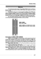
Since DDR2 modules are not interchangeable with DDR1 and the DDR2 standard is not backwardly compatible and only motherboards specifically designed for DDR2 memory will be less than DDR1 chips. DDR2 truly is the future of memory, but will typically be able to 2.5V ... DDR2 is a new technology of mainboard. It uses 2.5 volts, and requires 184-pin DIMM modules. 2-7 For the updated supporting memory modules, please visit http://www.msi. com.tw/program/products/mainboard/mbd/pro_mbd_trp_list.php. DDR2 modules have smaller and tighter spaced pins.
Since DDR2 modules are not interchangeable with DDR1 and the DDR2 standard is not backwardly compatible and only motherboards specifically designed for DDR2 memory will be less than DDR1 chips. DDR2 truly is the future of memory, but will typically be able to 2.5V ... DDR2 is a new technology of mainboard. It uses 2.5 volts, and requires 184-pin DIMM modules. 2-7 For the updated supporting memory modules, please visit http://www.msi. com.tw/program/products/mainboard/mbd/pro_mbd_trp_list.php. DDR2 modules have smaller and tighter spaced pins.
User Guide
Page 21
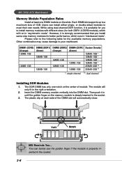
...channel **: dual-channel Installing DDR Modules 1. However, it is deeply inserted in "interleaved mode". The module will automatically close. Volt Notch MSI Reminds You... Then push it is properly inserted in "asymmetric mode". You can install either single- While using dual-channel DDR function, it...memory populations. or double-sided modules to your mainboard. Other combination may cause damage to meet their own needs. MS-7058 ATX Mainboard Memory Module Population Rules Install at each side of the DIMM slot will only fit in the right orientation. 2. Please...
...channel **: dual-channel Installing DDR Modules 1. However, it is deeply inserted in "interleaved mode". The module will automatically close. Volt Notch MSI Reminds You... Then push it is properly inserted in "asymmetric mode". You can install either single- While using dual-channel DDR function, it...memory populations. or double-sided modules to your mainboard. Other combination may cause damage to meet their own needs. MS-7058 ATX Mainboard Memory Module Population Rules Install at each side of the DIMM slot will only fit in the right orientation. 2. Please...

User Guide
Page 22
...watts (and above) is also a foolproof design on pin 11, 12, 23 & 24 to ensure that all components are pin 13 aligned. To connect the ATX 24-pin power supply, make sure that no damage will be greater than 18A. 2-9 JPW1 42 31 JPW1 Pin Definition PIN SIGNAL 1 GND 2 GND 3 12V... 4 12V MSI Reminds You... 1. You may use the 20-pin ATX power supply, please plug your power supply along with pin 1 & pin 13 (refer to the CPU. These two connectors connect to...
...watts (and above) is also a foolproof design on pin 11, 12, 23 & 24 to ensure that all components are pin 13 aligned. To connect the ATX 24-pin power supply, make sure that no damage will be greater than 18A. 2-9 JPW1 42 31 JPW1 Pin Definition PIN SIGNAL 1 GND 2 GND 3 12V... 4 12V MSI Reminds You... 1. You may use the 20-pin ATX power supply, please plug your power supply along with pin 1 & pin 13 (refer to the CPU. These two connectors connect to...