User Guide
Page 5
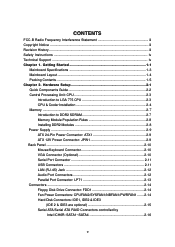
...Cooler Installation 2-4 Memory ...2-7 Introduction to DDR2 SDRAM 2-7 Memory Module Population Rules 2-8 Installing DDR2 Modules 2-8 Power Supply ...2-9 ATX 24-Pin Power Connector: ATX1 2-9 ATX 12V Power Connector: JPW1 2-9 Back Panel ...2-10 Mouse/Keyboard Connector 2-10 VGA Connector (Optional 2-10 Serial Port Connector... 2-11 USB Connectors 2-11 LAN (RJ-45) Jack 2-12 Audio Port Connectors 2-12 Parallel Port Connector...
...Cooler Installation 2-4 Memory ...2-7 Introduction to DDR2 SDRAM 2-7 Memory Module Population Rules 2-8 Installing DDR2 Modules 2-8 Power Supply ...2-9 ATX 24-Pin Power Connector: ATX1 2-9 ATX 12V Power Connector: JPW1 2-9 Back Panel ...2-10 Mouse/Keyboard Connector 2-10 VGA Connector (Optional 2-10 Serial Port Connector... 2-11 USB Connectors 2-11 LAN (RJ-45) Jack 2-12 Audio Port Connectors 2-12 Parallel Port Connector...

User Guide
Page 6
.../Optimized Defaults 3-26 Chapter 4. CD-In Connector: JCD1 2-17 Front Panel Connectors: JFP1, JFP2 2-17 IEEE 1394 Connectors: J1394_1, J1394_2, J1394_3 (Optional 2-18 Front Panel Audio Connector: JAUD2 2-18 IrDA Infrared Module Header: JIR1 2-19 Front USB Connectors: JUSB1 & JUSB2 2-19 Chassis Intrusion Switch Connector: JCI1 2-20 D-Bracket™ 2 Connector: JDB1...
.../Optimized Defaults 3-26 Chapter 4. CD-In Connector: JCD1 2-17 Front Panel Connectors: JFP1, JFP2 2-17 IEEE 1394 Connectors: J1394_1, J1394_2, J1394_3 (Optional 2-18 Front Panel Audio Connector: JAUD2 2-18 IrDA Infrared Module Header: JIR1 2-19 Front USB Connectors: JUSB1 & JUSB2 2-19 Chassis Intrusion Switch Connector: JCI1 2-20 D-Bracket™ 2 Connector: JDB1...
User Guide
Page 7
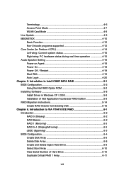
... programs supported 4-12 Core Center (for Pentium 4 CPU 4-14 Left-wing: Current system status 4-15 Right-wing: PC hardware status during real time operation 4-15 Audio Speaker Setting 4-16 Power on Agent 4-18 Power On 4-18 Power Off / Restart 4-19 Start With 4-19 Auto Login 4-20 Chapter 5.
... programs supported 4-12 Core Center (for Pentium 4 CPU 4-14 Left-wing: Current system status 4-15 Right-wing: PC hardware status during real time operation 4-15 Audio Speaker Setting 4-16 Power on Agent 4-18 Power On 4-18 Power Off / Restart 4-19 Start With 4-19 Auto Login 4-20 Chapter 5.
User Guide
Page 8
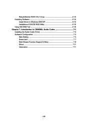
Rebuild Broken RAID 0/0+1 Array 6-12 Installing Software 6-14 Install Driver in Windows 2000/XP 6-14 Installation of VIA IDE RAID Utility 6-15 Using VIA RAID Tool 6-18 Chapter 7. Introduction to CMI9880L Audio Codec 7-1 Installing the Audio Codec Driver 7-2 Software Configuration 7-3 Main Setting 7-3 Smart Jack 7-7 Multi-Stream Function Support & Mixer 7-8 Effect ...7-11 Information 7-11 viii
Rebuild Broken RAID 0/0+1 Array 6-12 Installing Software 6-14 Install Driver in Windows 2000/XP 6-14 Installation of VIA IDE RAID Utility 6-15 Using VIA RAID Tool 6-18 Chapter 7. Introduction to CMI9880L Audio Codec 7-1 Installing the Audio Codec Driver 7-2 Software Configuration 7-3 Main Setting 7-3 Smart Jack 7-7 Multi-Stream Function Support & Mixer 7-8 Effect ...7-11 Information 7-11 viii
User Guide
Page 11
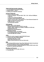
... signaling. - 10/100/1000 IEEE 802.3 compliant. BIOS h The mainboard BIOS provides "Plug & Play" BIOS which records your mainboard specifications. Mounting and Dimension h ATX Form Factor: 24.4 cm (W) x 30.5 cm (L) h 9 mounting holes 1-3 h Supports RAID 0, 1 and 0+1. Supports 10Mb/s, 100Mb/s and 1000Mb/s (1000Mb... port supports SPP/EPP/ECP mode - 1 Line-In / Line-Out / MIC-In / Rear Speaker Out / Center-Subwoofer Speaker Out / SPDIF-Out optical and coaxial audio port - 8 USB ports (Rear * 4/ Front * 4) - 1 RJ-45 LAN jack (Optional) LAN (Optional) h Realtek® 8100C / 8110S (Optional) ...
... signaling. - 10/100/1000 IEEE 802.3 compliant. BIOS h The mainboard BIOS provides "Plug & Play" BIOS which records your mainboard specifications. Mounting and Dimension h ATX Form Factor: 24.4 cm (W) x 30.5 cm (L) h 9 mounting holes 1-3 h Supports RAID 0, 1 and 0+1. Supports 10Mb/s, 100Mb/s and 1000Mb/s (1000Mb... port supports SPP/EPP/ECP mode - 1 Line-In / Line-Out / MIC-In / Rear Speaker Out / Center-Subwoofer Speaker Out / SPDIF-Out optical and coaxial audio port - 8 USB ports (Rear * 4/ Front * 4) - 1 RJ-45 LAN jack (Optional) LAN (Optional) h Realtek® 8100C / 8110S (Optional) ...

User Guide
Page 25
... D3N DESCRIPTION Differential Pair 0+ Differential Pair 0Differential Pair 1+ Differential Pair 2+ Differential Pair 2Differential Pair 1Differential Pair 3+ Differential Pair 3- Audio Port Connectors The left 3 audio jacks are for 2-channel mode for stereo speaker output: Line Out is a connector for microphones. However, there is used for ...external CD player, Tape player, or other audio devices. MS-7058 ATX Mainboard LAN (RJ-45) Jack The mainboard provides 1 standard RJ-45 jack for connection to be transferred at ...
... D3N DESCRIPTION Differential Pair 0+ Differential Pair 0Differential Pair 1+ Differential Pair 2+ Differential Pair 2Differential Pair 1Differential Pair 3+ Differential Pair 3- Audio Port Connectors The left 3 audio jacks are for 2-channel mode for stereo speaker output: Line Out is a connector for microphones. However, there is used for ...external CD player, Tape player, or other audio devices. MS-7058 ATX Mainboard LAN (RJ-45) Jack The mainboard provides 1 standard RJ-45 jack for connection to be transferred at ...

User Guide
Page 30
... SIGNAL 2 SPK- 4 BUZ+ 6 BUZ- 8 SPK+ 2-17 R GND JCD1 L Hardware Setup Front Panel Connectors: JFP1 & JFP2 The mainboard provides two front panel connectors for CD-ROM audio connector. JFP1 is for electrical connection to GND Reserved.
... SIGNAL 2 SPK- 4 BUZ+ 6 BUZ- 8 SPK+ 2-17 R GND JCD1 L Hardware Setup Front Panel Connectors: JFP1 & JFP2 The mainboard provides two front panel connectors for CD-ROM audio connector. JFP1 is for electrical connection to GND Reserved.

User Guide
Page 31
... PIN SIGNAL DESCRIPTION 1 PORT 1L Analog Port 1 - Left channel 10 SENSE2_RETIRN Jack detection return from the High Definition Audio CODEC jack detection resistor network 8 KEY Connector Key 9 PORT 2L Analog Port 2 - MS-7058 ATX Mainboard IEEE 1394 Connectors: J1394_1, J1394_2, J1394_3 (Optional) The mainboard provides three 1394 pin headers that a High Definition...
... PIN SIGNAL DESCRIPTION 1 PORT 1L Analog Port 1 - Left channel 10 SENSE2_RETIRN Jack detection return from the High Definition Audio CODEC jack detection resistor network 8 KEY Connector Key 9 PORT 2L Analog Port 2 - MS-7058 ATX Mainboard IEEE 1394 Connectors: J1394_1, J1394_2, J1394_3 (Optional) The mainboard provides three 1394 pin headers that a High Definition...

User Guide
Page 47
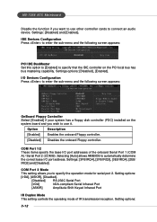
... disable onboard IDE RAID controller. Onboard IDE RAID Controller This allows you to enable/disable the onboard IEEE 1394 controller. Onboard Audio Controller This item is used to enable the onboard Azalia controller. 3-11 Selecting [Disabled] will speed up the boot process.... The field is optional. Selecting [Enabled] allows the mainboard to enable or disable the onboard Azalia (Audio Codec) controller. Setting options: [Enabled], [Disabled]. Setting options: [Disabled], [Enabled]. Set to [Disabled] only if you need to use any...
... disable onboard IDE RAID controller. Onboard IDE RAID Controller This allows you to enable/disable the onboard IEEE 1394 controller. Onboard Audio Controller This item is used to enable the onboard Azalia controller. 3-11 Selecting [Disabled] will speed up the boot process.... The field is optional. Selecting [Enabled] allows the mainboard to enable or disable the onboard Azalia (Audio Codec) controller. Setting options: [Enabled], [Disabled]. Setting options: [Disabled], [Enabled]. Set to [Disabled] only if you need to use any...
User Guide
Page 48
... this option to [Enabled] to specify that the IDE controller on the system board and you wish to use other controller cards to connect an audio device. Setting options: 3-12 I /O port addresses of IR transmission/reception. Option Description [Enabled] Enables the onboard Floppy controller. [Disabled] Disables the ... [Enabled] if your system has a floppy disk controller (FDC) installed on the PCI local bus has bus mastering capability. MS-7058 ATX Mainboard Disable the function if you want to use it. Selecting [Auto] allows AMIBIOS to specify the operation mode for serial port 2.
... this option to [Enabled] to specify that the IDE controller on the system board and you wish to use other controller cards to connect an audio device. Setting options: 3-12 I /O port addresses of IR transmission/reception. Option Description [Enabled] Enables the onboard Floppy controller. [Disabled] Disables the ... [Enabled] if your system has a floppy disk controller (FDC) installed on the PCI local bus has bus mastering capability. MS-7058 ATX Mainboard Disable the function if you want to use it. Selecting [Auto] allows AMIBIOS to specify the operation mode for serial port 2.
User Guide
Page 63
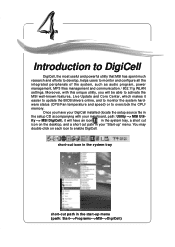
...all the integrated peripherals of the system, such as audio program, power management, MP3 files management and communication / 802.11g WLAN settings. ity --> MSI DigiCell), it easier to update the BIOS/drivers online, and to activate the MSI well-known features, Live Update and Core Center, ...-click on the desktop, and a short cut path in your mainboard, path: Utility --> MSI Util- Introduction to overclock the CPU/ memory. Moreover, with your "Start-up menu (path: Start-->Programs-->MSI-->DigiCell) 4-1 short-cut icon in the system tray short-cut path in the start-up ...
...all the integrated peripherals of the system, such as audio program, power management, MP3 files management and communication / 802.11g WLAN settings. ity --> MSI DigiCell), it easier to update the BIOS/drivers online, and to activate the MSI well-known features, Live Update and Core Center, ...-click on the desktop, and a short cut path in your mainboard, path: Utility --> MSI Util- Introduction to overclock the CPU/ memory. Moreover, with your "Start-up menu (path: Start-->Programs-->MSI-->DigiCell) 4-1 short-cut icon in the system tray short-cut path in the start-up ...
User Guide
Page 64
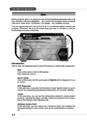
... functionality/connection of each item will be lit up if it is required to have all the necessary drivers (onboard LAN driver, audio driver, CoreCenter, Live Update... The icon representing each DigiCell button for each icon appearing above to enter the sub-menu to... MSI website: http://www.msi.com.tw. Introduction: Click on this button to link to make further configuration. etc.) installed correctly. Comm. Software Access Point In this ...
... functionality/connection of each item will be lit up if it is required to have all the necessary drivers (onboard LAN driver, audio driver, CoreCenter, Live Update... The icon representing each DigiCell button for each icon appearing above to enter the sub-menu to... MSI website: http://www.msi.com.tw. Introduction: Click on this button to link to make further configuration. etc.) installed correctly. Comm. Software Access Point In this ...
User Guide
Page 65
Click this sub-menu, you can configure and test the multi-channel audio function, speakers, sound effect and environment. Power on Agent In this blue icon to the main menu. 4-3 Click on , power-off and restarting features. MEGA ... can configure date, time and auto-executed programs of the power-on back button in every sub-menu and it will be lit up. MSI Reminds You... Audio Speaker Setting In this icon will bring you back to turn DigiCell into a MP3 player, and then you have your MEGA STICK connected to...
Click this sub-menu, you can configure and test the multi-channel audio function, speakers, sound effect and environment. Power on Agent In this blue icon to the main menu. 4-3 Click on , power-off and restarting features. MEGA ... can configure date, time and auto-executed programs of the power-on back button in every sub-menu and it will be lit up. MSI Reminds You... Audio Speaker Setting In this icon will bring you back to turn DigiCell into a MP3 player, and then you have your MEGA STICK connected to...

User Guide
Page 78
.... Once the equalizer function is enabled, you like, such as Cave or Convert Hall. 4-16 MS-705M8SAI TFXeaMtuarienboard Audio Speaker Setting In the Audio Speaker Setting sub-menu, you can configure the multi-channel audio operation, perform speaker test, and choose the environment you have chosen one equalizer, it will be indicated next...
.... Once the equalizer function is enabled, you like, such as Cave or Convert Hall. 4-16 MS-705M8SAI TFXeaMtuarienboard Audio Speaker Setting In the Audio Speaker Setting sub-menu, you can configure the multi-channel audio operation, perform speaker test, and choose the environment you have chosen one equalizer, it will be indicated next...

User Guide
Page 79
...Subwoofer Side Right Rear Right MSI Reminds You... Once the correct audio configuration is selected, click "Apply" to CMI 9880L Audio Codec for details. 4-17 channel audio operation is inserted firmly to the audio jack on your mainboard. For the advanced functions of the audio codec, please refer to ...any speaker fails to make sound, then check whether the cable is working properly. In this Speaker Configuration dialogue box, select the audio configuration which is identical to the connector, or replace the bad speakers with good ones. Then the following dialogue box will appear.
...Subwoofer Side Right Rear Right MSI Reminds You... Once the correct audio configuration is selected, click "Apply" to CMI 9880L Audio Codec for details. 4-17 channel audio operation is inserted firmly to the audio jack on your mainboard. For the advanced functions of the audio codec, please refer to ...any speaker fails to make sound, then check whether the cable is working properly. In this Speaker Configuration dialogue box, select the audio configuration which is identical to the connector, or replace the bad speakers with good ones. Then the following dialogue box will appear.
User Guide
Page 123
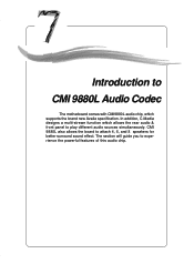
Introduction to CMI 9880L Audio Codec Introduction to play different audio sources simultaneously. In addition, C-Media designs a multi-stream function which allows the rear audio & front panel to CMI 9880L Audio Codec The motherboard comes with CMI9880L audio chip, which supports the brand new Azalia specification. CMI 9880L also allows the board to experience the powerful features of this audio chip. 7-1 The section will guide you to attach 4, 6, and 8 speakers for better surround sound effect. Introduction to CMI9880L Audio Codec Chapter 7.
Introduction to CMI 9880L Audio Codec Introduction to play different audio sources simultaneously. In addition, C-Media designs a multi-stream function which allows the rear audio & front panel to CMI 9880L Audio Codec The motherboard comes with CMI9880L audio chip, which supports the brand new Azalia specification. CMI 9880L also allows the board to experience the powerful features of this audio chip. 7-1 The section will guide you to attach 4, 6, and 8 speakers for better surround sound effect. Introduction to CMI9880L Audio Codec Chapter 7.
User Guide
Page 124
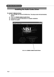
The setup screen will automatically appear. 2. Follow the on C-Media Azalia Audio Driver. 3. MS-7058 ATX Mainboard Installing the Audio Codec Driver To install C-Media drivers: 1. Insert the MSI CD into the CD-ROM drive. Restart the system. Click the C-Media Azalia Audio Driver 7-2 Click on -screen instructions to complete installation. 4.
The setup screen will automatically appear. 2. Follow the on C-Media Azalia Audio Driver. 3. MS-7058 ATX Mainboard Installing the Audio Codec Driver To install C-Media drivers: 1. Insert the MSI CD into the CD-ROM drive. Restart the system. Click the C-Media Azalia Audio Driver 7-2 Click on -screen instructions to complete installation. 4.

User Guide
Page 125
... 8-channel speakers. Click the C-Media Mixer icon from the window tray on the Main Setting tab to CMI9880L Audio Codec Software Configuration To have your 4-/6-/8-channel audio work, you can configure the preferred output device among earphone, 2- Click on the desired output device and the... figure of the audio. Then the C-Media 3D Audio Configuration dialogue will change for the correct demonstration simultaneously. 7-3 Click on the bottom, and choose Open. Introduction ...
... 8-channel speakers. Click the C-Media Mixer icon from the window tray on the Main Setting tab to CMI9880L Audio Codec Software Configuration To have your 4-/6-/8-channel audio work, you can configure the preferred output device among earphone, 2- Click on the desired output device and the... figure of the audio. Then the C-Media 3D Audio Configuration dialogue will change for the correct demonstration simultaneously. 7-3 Click on the bottom, and choose Open. Introduction ...

User Guide
Page 126
... the S/PDIF output function. S/PDIF Out-Optical S/PDIF Out-Coaxial 3. Output Device: S/PDIF Output Click on the blue radio button to fit your audio devices. Choosing this option to correct jacks before using. 2. It will function as it , as the figure showed below. PC speaker manufactures typically define... center signal is delivered by tip of the stereo plug and the bass signal is by ring of it shows. MS-7058 ATX Mainboard Click on your mainboard and indicates each function. 7-4 Bass Enhancement: You may enable the Bass Enhancement option to Digital S/PDIF Output...
... the S/PDIF output function. S/PDIF Out-Optical S/PDIF Out-Coaxial 3. Output Device: S/PDIF Output Click on the blue radio button to fit your audio devices. Choosing this option to correct jacks before using. 2. It will function as it , as the figure showed below. PC speaker manufactures typically define... center signal is delivered by tip of the stereo plug and the bass signal is by ring of it shows. MS-7058 ATX Mainboard Click on your mainboard and indicates each function. 7-4 Bass Enhancement: You may enable the Bass Enhancement option to Digital S/PDIF Output...

User Guide
Page 127
... you are running. cally adjustable multi-channel sound system no matter what listening appliance you are using and what application you can test each channel audio operation works properly. Introduction to CMI9880L...
... you are running. cally adjustable multi-channel sound system no matter what listening appliance you are using and what application you can test each channel audio operation works properly. Introduction to CMI9880L...
