
User Guide
Page 4
... only with your place of the following help resources for further guidance. † Visit the MSI homepage & FAQ site for technical guide, BIOS updates, driver updates, and other information: http://www.msi.com.tw & http://www. Make sure the voltage of the power source and adjust properly ... or cause electri- The openings on the equipment should be obtained from humidity. 4. iv msi.com.tw/program/service/faq/faq/esc_faq_list.php † Contact our technical staff at: support@msi.com.tw Safety Instructions 1. cal shock. 11. All cautions and warnings on the enclosure...
... only with your place of the following help resources for further guidance. † Visit the MSI homepage & FAQ site for technical guide, BIOS updates, driver updates, and other information: http://www.msi.com.tw & http://www. Make sure the voltage of the power source and adjust properly ... or cause electri- The openings on the equipment should be obtained from humidity. 4. iv msi.com.tw/program/service/faq/faq/esc_faq_list.php † Contact our technical staff at: support@msi.com.tw Safety Instructions 1. cal shock. 11. All cautions and warnings on the enclosure...

User Guide
Page 6
...4-20 Using 2-, 4-, 6- & 8- IEEE 1394 Connectors: J1394 (optional 2-20 IrDA Infrared Module Header: JIR1 2-20 Jumpers 2-21 BIOS Flash Jumper: BIOS_WP 2-21 Clear CMOS Jumper: JBAT1 2-21 Slots 2-22 PCI Express Slots 2-22 PCI (Peripheral Component Interconnect) Slots 2-...23 PCI Interrupt Request Routing 2-23 Chapter 3. BIOS Setup 3-1 Entering Setup 3-2 Selecting the First Boot Device 3-2 Control Keys 3-2 Getting Help 3-2 Main Menu 3-2 Default Settings 3-2 The Main Menu 3-3 Standard CMOS Features 3-6 Advanced BIOS Features 3-8 Advanced Chipset Features 3-11 Integrated ...
...4-20 Using 2-, 4-, 6- & 8- IEEE 1394 Connectors: J1394 (optional 2-20 IrDA Infrared Module Header: JIR1 2-20 Jumpers 2-21 BIOS Flash Jumper: BIOS_WP 2-21 Clear CMOS Jumper: JBAT1 2-21 Slots 2-22 PCI Express Slots 2-22 PCI (Peripheral Component Interconnect) Slots 2-...23 PCI Interrupt Request Routing 2-23 Chapter 3. BIOS Setup 3-1 Entering Setup 3-2 Selecting the First Boot Device 3-2 Control Keys 3-2 Getting Help 3-2 Main Menu 3-2 Default Settings 3-2 The Main Menu 3-3 Standard CMOS Features 3-6 Advanced BIOS Features 3-8 Advanced Chipset Features 3-11 Integrated ...
User Guide
Page 10
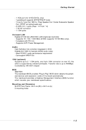
... On-board LAN † Realtek 8110S Gb LAN/8100C LAN (Optional) Controller - Transfer rate is supported by VIA 6307 chipset BIOS † 4Mb FWH † The mainboard BIOS provides "Plug & Play" BIOS which detects the peripheral devices and expansion cards of the board automatically † The mainboard provides a Desktop Management Interface (DMI) function...
... On-board LAN † Realtek 8110S Gb LAN/8100C LAN (Optional) Controller - Transfer rate is supported by VIA 6307 chipset BIOS † 4Mb FWH † The mainboard BIOS provides "Plug & Play" BIOS which detects the peripheral devices and expansion cards of the board automatically † The mainboard provides a Desktop Management Interface (DMI) function...
User Guide
Page 18
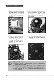
Turn over the mainboard to p.3-20 for details) for the CPU temperature. 3. locking switch MSI Reminds You... 1. Make sure that the clip-ends are not turned up or pressed down lightly onto the load plate, and then secure the lever .... Confirm if your CPU heatsink/cooler is firmly installed before turning on the mainboard with the hook under retention tab. 10. Check the information in BIOS (refer to confirm that the CPU socket pins are corrected inserted. Press the four hooks down the fan/heatsink until its four clips get wedged...
Turn over the mainboard to p.3-20 for details) for the CPU temperature. 3. locking switch MSI Reminds You... 1. Make sure that the clip-ends are not turned up or pressed down lightly onto the load plate, and then secure the lever .... Confirm if your CPU heatsink/cooler is firmly installed before turning on the mainboard with the hook under retention tab. 10. Check the information in BIOS (refer to confirm that the CPU socket pins are corrected inserted. Press the four hooks down the fan/heatsink until its four clips get wedged...

User Guide
Page 27
... Connector: IDE1 The mainboard has 1 IDE port and support the following function in the list. You must configure second hard drive to a 2-pin chassis switch. MSI Reminds You... Chassis Intrusion Switch Connector: JCASE1 This connector is opened, the switch will record this status and show a warning message on cable, you must... configure the second drive to IDE1. To clear the warning, you must enter the BIOS utility and clear the record. 2 GND CINTRU 1 JCASE1 2-15 IDE1 can connect a Master and a Slave drive.
... Connector: IDE1 The mainboard has 1 IDE port and support the following function in the list. You must configure second hard drive to a 2-pin chassis switch. MSI Reminds You... Chassis Intrusion Switch Connector: JCASE1 This connector is opened, the switch will record this status and show a warning message on cable, you must... configure the second drive to IDE1. To clear the warning, you must enter the BIOS utility and clear the record. 2 GND CINTRU 1 JCASE1 2-15 IDE1 can connect a Master and a Slave drive.
User Guide
Page 30
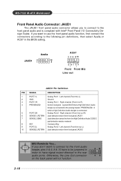
... AC97 2 4 6 8 10 5 91 7 3 Front Front Mic Line-out JAUD1 Pin Definition PIN SIGNAL DESCRIPTION 1 PORT 1L Analog Port 1 - signals BIOS that a High Definition Audio dongle is connected. 5 PORT 2R Analog Port 2 - PRESENCE# = 0 when a High Definition Audio dongle is connected to the ... (Front line-out R) 6 SENSE1_RETIRN Jack detection return from front panel JACK1 7 SENSE_SEND Jack detection sense line from front panel JACK2 2-18 MSI Reminds You... M S-7133 M -ATX M ainboard Front Panel Audio Connector: JAUD1 The JAUD1 front panel audio connector allows you don't want...
... AC97 2 4 6 8 10 5 91 7 3 Front Front Mic Line-out JAUD1 Pin Definition PIN SIGNAL DESCRIPTION 1 PORT 1L Analog Port 1 - signals BIOS that a High Definition Audio dongle is connected. 5 PORT 2R Analog Port 2 - PRESENCE# = 0 when a High Definition Audio dongle is connected to the ... (Front line-out R) 6 SENSE1_RETIRN Jack detection return from front panel JACK1 7 SENSE_SEND Jack detection sense line from front panel JACK2 2-18 MSI Reminds You... M S-7133 M -ATX M ainboard Front Panel Audio Connector: JAUD1 The JAUD1 front panel audio connector allows you don't want...
User Guide
Page 32
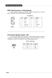
... power Ground IrDA Infrared Module Header: JIR1 The connector allows you to connect to use the IR function. You must configure the setting through the BIOS setup to IrDA Infrared module. JIR1 Pin Definition 5 1 6 2 JIR1 Pin Signal Pin 1 NC 2 3 VCC5 4 5 IRTX 6 Signal NC GND IRRX 2-20...
... power Ground IrDA Infrared Module Header: JIR1 The connector allows you to connect to use the IR function. You must configure the setting through the BIOS setup to IrDA Infrared module. JIR1 Pin Definition 5 1 6 2 JIR1 Pin Signal Pin 1 NC 2 3 VCC5 4 5 IRTX 6 Signal NC GND IRRX 2-20...

User Guide
Page 33
... the system can clear CMOS by shorting 2-3 pin while the system is a CMOS RAM on . Follow the instructions below to 1-2 pin position. BIOS Flash Jumper: BIOS_WP This jumper is turned on board that has a power supply from external battery to keep the system configuration data. W hen locked,... the BIOS boot block area cannot be updated. Then return to clear the data: 1 JBAT1 1 3 Keep Data 1 3 Clear Data MSI Reminds You... it is used to lock or unlock the boot block area on ; This ...
... the system can clear CMOS by shorting 2-3 pin while the system is a CMOS RAM on . Follow the instructions below to 1-2 pin position. BIOS Flash Jumper: BIOS_WP This jumper is turned on board that has a power supply from external battery to keep the system configuration data. W hen locked,... the BIOS boot block area cannot be updated. Then return to clear the data: 1 JBAT1 1 3 Keep Data 1 3 Clear Data MSI Reminds You... it is used to lock or unlock the boot block area on ; This ...
User Guide
Page 35
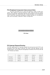
... for the expansion card to make sure that you to insert the expansion cards to the PCI bus INT A# ~ INT D# pins as jumpers, switches or BIOS configuration. The PCI IRQ pins are hardware lines over which devices can send interrupt signals to the microprocessor. Meanwhile, read the documentation for the expansion...
... for the expansion card to make sure that you to insert the expansion cards to the PCI bus INT A# ~ INT D# pins as jumpers, switches or BIOS configuration. The PCI IRQ pins are hardware lines over which devices can send interrupt signals to the microprocessor. Meanwhile, read the documentation for the expansion...
User Guide
Page 36
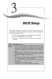
... up , and requests you to configure the system for better system performance. BIOS Setup Chapter 3. It is shown in the format: example: A7133IMS V1.0BH 01/23/05 where: 1st digit refers to the date this chap- MSI Reminds You... 1. W=AWARD(R) 2nd - 5th digit refers to the model number.... 6th - 7th digit refers to change the default settings for reference only. 2. V1.0BH refers to the BIOS version. 01/23/05 refers to BIOS maker as A=AMI(R); BIOS BIOS Setup This chapter provides ...
... up , and requests you to configure the system for better system performance. BIOS Setup Chapter 3. It is shown in the format: example: A7133IMS V1.0BH 01/23/05 where: 1st digit refers to the date this chap- MSI Reminds You... 1. W=AWARD(R) 2nd - 5th digit refers to the model number.... 6th - 7th digit refers to change the default settings for reference only. 2. V1.0BH refers to the BIOS version. 01/23/05 refers to BIOS maker as A=AMI(R); BIOS BIOS Setup This chapter provides ...

User Guide
Page 37
.... You may also restart the system by pressing . Selecting the First Boot Device You are allowed to select the 1st boot device without entering the BIOS setup utility by simultaneously pressing , , and keys. M S-7133 M -ATX M ainboard Entering Setup Power on the computer and the system will still use the ... DEL: Setup Menu TAB: Logo F11: Boot Menu F10: Flash Recovery If the message disappears before you respond and you to respond in the BIOS setup utility, so next time when you want to boot from the selected device. The POST messages might pass by too quickly for you still...
.... You may also restart the system by pressing . Selecting the First Boot Device You are allowed to select the 1st boot device without entering the BIOS setup utility by simultaneously pressing , , and keys. M S-7133 M -ATX M ainboard Entering Setup Power on the computer and the system will still use the ... DEL: Setup Menu TAB: Logo F11: Boot Menu F10: Flash Recovery If the message disappears before you respond and you to respond in the BIOS setup utility, so next time when you want to boot from the selected device. The POST messages might pass by too quickly for you still...
User Guide
Page 38
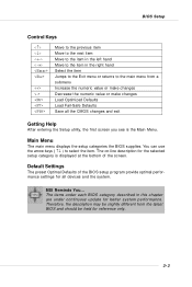
... devices and the system. Default Settings The preset Optimal Defaults of the screen. You can use the arrow keys ( ↑↓ ) to select the item. BIOS Setup Control Keys Enter> Move to the previous item Move to the next item Move to the item in the left hand Move to the... all the CMOS changes and exit Getting Help After entering the Setup utility, the first screen you see is displayed at the bottom of the BIOS setup program provide optimal performance settings for reference only. 3-3 MSI Reminds You... Main Menu The main menu displays the setup categories the...
... devices and the system. Default Settings The preset Optimal Defaults of the screen. You can use the arrow keys ( ↑↓ ) to select the item. BIOS Setup Control Keys Enter> Move to the previous item Move to the next item Move to the item in the left hand Move to the... all the CMOS changes and exit Getting Help After entering the Setup utility, the first screen you see is displayed at the bottom of the BIOS setup program provide optimal performance settings for reference only. 3-3 MSI Reminds You... Main Menu The main menu displays the setup categories the...
User Guide
Page 39
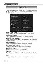
... frequency/voltage control. 3-4 M S-7133 M -ATX M ainboard The Main Menu Once you enter AMIBIOS NEW SETUP UTILITY, the Main Menu will appear on the screen. Advanced BIOS Features Use this menu to setup the items of your settings for overall system status. PNP/PCI Configurations This entry appears if your settings for...
... frequency/voltage control. 3-4 M S-7133 M -ATX M ainboard The Main Menu Once you enter AMIBIOS NEW SETUP UTILITY, the Main Menu will appear on the screen. Advanced BIOS Features Use this menu to setup the items of your settings for overall system status. PNP/PCI Configurations This entry appears if your settings for...
User Guide
Page 40
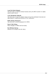
BIOS Setting Password Use this menu to set the password for stable system performance. Save & Exit Setup Save changes to load the default values set by the BIOS vendor for BIOS. BIOS Setup Load Fail-Safe Defaults Use this menu to load the default values set by the mainboard manufacturer specifically for optimal performance of the mainboard. Load Optimized Defaults Use this menu to CMOS and exit setup. Exit Without Saving Abandon all changes and exit setup. 3-5
BIOS Setting Password Use this menu to set the password for stable system performance. Save & Exit Setup Save changes to load the default values set by the BIOS vendor for BIOS. BIOS Setup Load Fail-Safe Defaults Use this menu to load the default values set by the mainboard manufacturer specifically for optimal performance of the mainboard. Load Optimized Defaults Use this menu to CMOS and exit setup. Exit Without Saving Abandon all changes and exit setup. 3-5
User Guide
Page 41
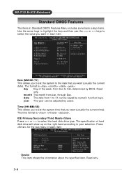
The specification of each item. day Day of the week, from Jan. through Dec. year The year can be adjusted by BIOS. Read-only. 3-6 Date (MM:DD:YY) This allows you to set the system time that you want (usually the current date). mon th The month ...
The specification of each item. day Day of the week, from Jan. through Dec. year The year can be adjusted by BIOS. Read-only. 3-6 Date (MM:DD:YY) This allows you to set the system time that you want (usually the current date). mon th The month ...
User Guide
Page 42
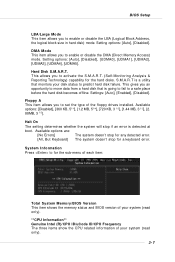
... (Self-Monitoring Analysis & Reporting Technology) capability for the sub-menu of each item: Total System M emory/BIOS Version This item shows the memory status and BIOS version of your system (read only). **CPU Information** Genuine Intel (R)/CPU ID/uCode ID/CPU Frequency The...], [UDMA0], [UDMA1], [UDMA2], [UDMA3], [UDMA4], [UDMA5]. Available options: [Disabled], [360 KB, 51/4], [1.2 MB, 51/4], [720 KB, 3 1/2], [1.44 MB, 3 1/2], [2. 88MB, 3 1/2]. BIOS Setup LBA/Large Mode This item allows you to a safe place before the hard disk becomes offline. The system doesn't stop if an error is...
... (Self-Monitoring Analysis & Reporting Technology) capability for the sub-menu of each item: Total System M emory/BIOS Version This item shows the memory status and BIOS version of your system (read only). **CPU Information** Genuine Intel (R)/CPU ID/uCode ID/CPU Frequency The...], [UDMA0], [UDMA1], [UDMA2], [UDMA3], [UDMA4], [UDMA5]. Available options: [Disabled], [360 KB, 51/4], [1.2 MB, 51/4], [720 KB, 3 1/2], [1.44 MB, 3 1/2], [2. 88MB, 3 1/2]. BIOS Setup LBA/Large Mode This item allows you to a safe place before the hard disk becomes offline. The system doesn't stop if an error is...
User Guide
Page 43
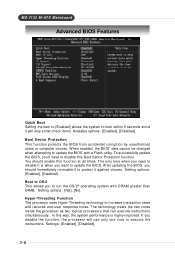
... it is highly improved. If you 'll need to run the OS/2® operating system with a Flash utility. To successfully update the BIOS, you disable the function, the processor will skip some check items. Available options: [Enabled], [Disabled]. Setting options: [Enabled], [Disabled...when you to disable it against viruses. Boot Sector Protection This function protects the BIOS from accidental corruption by unauthorized users or computer viruses. M S-7133 M -ATX M ainboard Advanced BIOS Features Quick Boot Setting the item to [Enabled] allows the system to increase transaction...
... it is highly improved. If you 'll need to run the OS/2® operating system with a Flash utility. To successfully update the BIOS, you disable the function, the processor will skip some check items. Available options: [Enabled], [Disabled]. Setting options: [Enabled], [Disabled...when you to disable it against viruses. Boot Sector Protection This function protects the BIOS from accidental corruption by unauthorized users or computer viruses. M S-7133 M -ATX M ainboard Advanced BIOS Features Quick Boot Setting the item to [Enabled] allows the system to increase transaction...

User Guide
Page 44
...appear. To find out which MPS (Multi-Processor Specification) version to be used to lower the CPU power consumption while idle. BIOS Setup MSI Reminds You... Settings: [Enabled], [Disabled]. Intel(R) SpeedStep(tm) tech When you can prevent viruses from proliferating. Settings are ... CPU: An Intel® Pentium® 4 Processor with HT Technology; * Chipset: An Intel® Chipset that supports HT Technology; * BIOS: A BIOS that supports HT Technology. M PS Table Version This field allows you to select the MPS version supported by your operating system. Settings: [Enabled...
...appear. To find out which MPS (Multi-Processor Specification) version to be used to lower the CPU power consumption while idle. BIOS Setup MSI Reminds You... Settings: [Enabled], [Disabled]. Intel(R) SpeedStep(tm) tech When you can prevent viruses from proliferating. Settings are ... CPU: An Intel® Pentium® 4 Processor with HT Technology; * Chipset: An Intel® Chipset that supports HT Technology; * BIOS: A BIOS that supports HT Technology. M PS Table Version This field allows you to select the MPS version supported by your operating system. Settings: [Enabled...
User Guide
Page 46
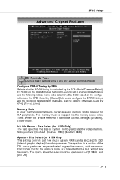
...determined by the SPD (Serial Presence Detect) EEPROM on the SPD. Setting options: [Manual], [Auto By SPD], [Turbo], [Ultra]. The aperture is controlled by BIOS based on the configurations on the DRAM module. Selecting [Manual] lets users configure the DRAM timings and the following related items to [Auto By SPD... of system memory allocated for video purposes. Configure DRAM Timing by SPD Selects whether DRAM timing is a portion of [128MB], and [256 MB]. 3-11 BIOS Setup Advanced Chipset Features MSI Reminds You... This memory must be mapped into the memory space below 16MB.
...determined by the SPD (Serial Presence Detect) EEPROM on the SPD. Setting options: [Manual], [Auto By SPD], [Turbo], [Ultra]. The aperture is controlled by BIOS based on the configurations on the DRAM module. Selecting [Manual] lets users configure the DRAM timings and the following related items to [Auto By SPD... of system memory allocated for video purposes. Configure DRAM Timing by SPD Selects whether DRAM timing is a portion of [128MB], and [256 MB]. 3-11 BIOS Setup Advanced Chipset Features MSI Reminds You... This memory must be mapped into the memory space below 16MB.
User Guide
Page 48
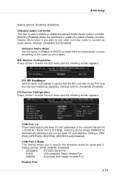
.... Setting options: [IrDA], [ASKIR], [Disabled]. [Disabled] RS-232C Serial Port [IrDA] IrDA-compliant Serial Infrared Port [ASKIR] Amplitude Shift Keyed Infrared Port Parallel Port 3-13 BIOS Setup Setting options: [Enabled], [Disabled]. Onboard Audio Controller This item is used to connect an audio device. Settings: [3F8/ IRQ4], [2F8/IRQ3], [3E8/IRQ4], [2E8...
.... Setting options: [IrDA], [ASKIR], [Disabled]. [Disabled] RS-232C Serial Port [IrDA] IrDA-compliant Serial Infrared Port [ASKIR] Amplitude Shift Keyed Infrared Port Parallel Port 3-13 BIOS Setup Setting options: [Enabled], [Disabled]. Onboard Audio Controller This item is used to connect an audio device. Settings: [3F8/ IRQ4], [2F8/IRQ3], [3E8/IRQ4], [2E8...


