User Guide
Page 2
.... Netware® is a registered trademark of American Megatrends Inc. AMI® is a registered trademark of Novell, Inc. Visit the MSI website for further guidance. W indows® XP/Vista are under continual improvement and we reserve the right to the correctness of Microsoft Corporation.... Alternatively, please try the following help resources for FAQ, technical guide, BIOS updates, driver updates, and other countries. Copyright Notice The material in this document, but no solution can be obtained from the...
.... Netware® is a registered trademark of American Megatrends Inc. AMI® is a registered trademark of Novell, Inc. Visit the MSI website for further guidance. W indows® XP/Vista are under continual improvement and we reserve the right to the correctness of Microsoft Corporation.... Alternatively, please try the following help resources for FAQ, technical guide, BIOS updates, driver updates, and other countries. Copyright Notice The material in this document, but no solution can be obtained from the...
User Guide
Page 8
... ...2-6 Power Supply ...2-8 Back Panel ...2-9 Connectors ...2-11 Buttons ...2-18 Switc h ...2-19 Slots ...2-20 Chapter 3 BIOS Setup 3-1 Entering Setup ...3-2 The Main Menu ...3-4 Standard CMOS Features 3-6 Advanced BIOS Features 3-9 Integrated Peripherals 3-12 Power Management Setup 3-14 H/W Monitor ...3-17 Green Power ...3-18 BIOS Setting Password 3-19 Cell Menu ...3-20 User Settings ...3-25 Load Fail-Safe/Optimized Defaults...
... ...2-6 Power Supply ...2-8 Back Panel ...2-9 Connectors ...2-11 Buttons ...2-18 Switc h ...2-19 Slots ...2-20 Chapter 3 BIOS Setup 3-1 Entering Setup ...3-2 The Main Menu ...3-4 Standard CMOS Features 3-6 Advanced BIOS Features 3-9 Integrated Peripherals 3-12 Power Management Setup 3-14 H/W Monitor ...3-17 Green Power ...3-18 BIOS Setting Password 3-19 Cell Menu ...3-20 User Settings ...3-25 Load Fail-Safe/Optimized Defaults...

User Guide
Page 27
...the actual CPU and system temperature. 3. the black wire is Ground and should be connected to take advantage of speed for the SYSFAN1/2 in BIOS. SYSFAN1/2 support fan control, too. Chassis Intrusion Connector: JCI1 This connector connects to the recommended CPU fans at processor's official website or ...consult the vendors for CPUFAN1. 4. If the mainboard has a System Hardware Monitor chipset on the screen. To clear the warning, you must enter the BIOS utility and clear the record. 1 CINTRU 2 GND JCI1 2-13 Fan/heatsink with speed sensor to the +12V; GND +1 2V SE NS OR GND...
...the actual CPU and system temperature. 3. the black wire is Ground and should be connected to take advantage of speed for the SYSFAN1/2 in BIOS. SYSFAN1/2 support fan control, too. Chassis Intrusion Connector: JCI1 This connector connects to the recommended CPU fans at processor's official website or ...consult the vendors for CPUFAN1. 4. If the mainboard has a System Hardware Monitor chipset on the screen. To clear the warning, you must enter the BIOS utility and clear the record. 1 CINTRU 2 GND JCI1 2-13 Fan/heatsink with speed sensor to the +12V; GND +1 2V SE NS OR GND...
User Guide
Page 35
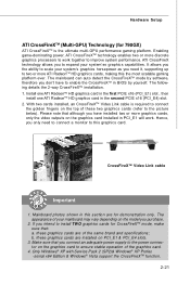
ATI CrossFireX technology allows you to enable the CrossFireXTM in BIOS by software, therefore you the ability to scale your mainboard may vary depending on the graphics card installed in PCI_E1 will work together to ensure ... x64 Edition & Windows® Vista support the CrossFireXTM function. 2-21 these graphics cards are for demonstration only. Hardware Setup ATI CrossFireXTM (Multi-GPU) Technology (for 790GX) ATI CrossFireXTM is required to connect the golden fingers on the top of these two graphics cards (refer to this graphics card. Enabling game-dominating...
ATI CrossFireX technology allows you to enable the CrossFireXTM in BIOS by software, therefore you the ability to scale your mainboard may vary depending on the graphics card installed in PCI_E1 will work together to ensure ... x64 Edition & Windows® Vista support the CrossFireXTM function. 2-21 these graphics cards are for demonstration only. Hardware Setup ATI CrossFireXTM (Multi-GPU) Technology (for 790GX) ATI CrossFireXTM is required to connect the golden fingers on the top of these two graphics cards (refer to this graphics card. Enabling game-dominating...

User Guide
Page 38
...MS-7576 Mainboard 2. Select Enable CrossFireTM 5. From the Graphics Adapter list, select the graphics card that acts as are all cards in Advanced BIOS Features -> Chipset Feature -> On-Chip VGA 4. Disable the Hybrid CrossFire in the CatalystTM Control Center, click CrossFireTM. 3. Reboot into... BIOS 3. Select the option in the configuration as the Display GPU. 4. W hen Hybrid CrossFireX is enabled, GPU Accelerated Physics is automatically disabled for...
...MS-7576 Mainboard 2. Select Enable CrossFireTM 5. From the Graphics Adapter list, select the graphics card that acts as are all cards in Advanced BIOS Features -> Chipset Feature -> On-Chip VGA 4. Disable the Hybrid CrossFire in the CatalystTM Control Center, click CrossFireTM. 3. Reboot into... BIOS 3. Select the option in the configuration as the Display GPU. 4. W hen Hybrid CrossFireX is enabled, GPU Accelerated Physics is automatically disabled for...
User Guide
Page 39
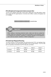
... and 33 MHz, it yields a throughput rate of interrupt request line and pronounced I-R-Q, are typically connected to the PCI bus pins as jumpers, switches or BIOS configuration. The PCI IRQ pins are hardware lines over which devices can send interrupt signals to configure any necessary hardware or software settings for the...
... and 33 MHz, it yields a throughput rate of interrupt request line and pronounced I-R-Q, are typically connected to the PCI bus pins as jumpers, switches or BIOS configuration. The PCI IRQ pins are hardware lines over which devices can send interrupt signals to configure any necessary hardware or software settings for the...
User Guide
Page 40
You may need to run the Setup program when: ² An error message appears on the BIOS Setup program and allows you to run SETUP. ² You want to configure the system for customized features. 3-1 Chapter 3 BIOS Setup BIOS Setup This chapter provides information on the screen during the system booting up, and requests you to change the default settings for optimum use.
You may need to run the Setup program when: ² An error message appears on the BIOS Setup program and allows you to run SETUP. ² You want to configure the system for customized features. 3-1 Chapter 3 BIOS Setup BIOS Setup This chapter provides information on the screen during the system booting up, and requests you to change the default settings for optimum use.

User Guide
Page 41
...7th - 8th digit refers to enter Setup, restart the system by simultaneously pressing , , and keys. You may be slightly different from the latest BIOS and should be held for better system performance. Important 1. The items under continuous update for reference only. 2. Upon boot-up, the 1st line ...appearing after the memory count is usually in this BIOS was released. 3-2 W hen the message below appears on the computer and the system will start POST (Power On Self Test) process. Therefore...
...7th - 8th digit refers to enter Setup, restart the system by simultaneously pressing , , and keys. You may be slightly different from the latest BIOS and should be held for better system performance. Important 1. The items under continuous update for reference only. 2. Upon boot-up, the 1st line ...appearing after the memory count is usually in this BIOS was released. 3-2 W hen the message below appears on the computer and the system will start POST (Power On Self Test) process. Therefore...
User Guide
Page 42
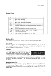
... within a sub-menu. Then you can use the arrow keys ( ↑↓ ) to select the item. General Help The BIOS setup program provides a General Help screen. You can call up this field. BIOS Setup Control Keys Enter> Move to the previous item Move to the next item Move to the item in...
... within a sub-menu. Then you can use the arrow keys ( ↑↓ ) to select the item. General Help The BIOS setup program provides a General Help screen. You can call up this field. BIOS Setup Control Keys Enter> Move to the previous item Move to the next item Move to the item in...

User Guide
Page 43
...enhanced features. Green Power Use this menu to specify your settings for power management. Integrated Peripherals Use this menu to set the password for BIOS. BIOS Setting Password Use this menu to specify your settings for integrated peripherals. MS-7576 Mainboard The Main Menu Standard CMOS Features Use this menu to... specify your settings for frequency/voltage control and overclocking. Cell Menu Use this menu for BIOS. 3-4 User Settings Use this menu to / from CMOS for basic system configurations, such as time, date etc. Advanced...
...enhanced features. Green Power Use this menu to specify your settings for power management. Integrated Peripherals Use this menu to set the password for BIOS. BIOS Setting Password Use this menu to specify your settings for integrated peripherals. MS-7576 Mainboard The Main Menu Standard CMOS Features Use this menu to... specify your settings for frequency/voltage control and overclocking. Cell Menu Use this menu for BIOS. 3-4 User Settings Use this menu to / from CMOS for basic system configurations, such as time, date etc. Advanced...

User Guide
Page 44
Save & Exit Setup Save changes to CMOS and exit setup. Load Optimized Defaults Use this menu to load the default values set by the BIOS vendor for optimal performance of the mainboard. BIOS Setup Load Fail-Safe Defaults Use this menu to load the default values set by the mainboard manufacturer specifically for stable system performance. Exit Without Saving Abandon all changes and exit setup. 3-5
Save & Exit Setup Save changes to CMOS and exit setup. Load Optimized Defaults Use this menu to load the default values set by the BIOS vendor for optimal performance of the mainboard. BIOS Setup Load Fail-Safe Defaults Use this menu to load the default values set by the mainboard manufacturer specifically for stable system performance. Exit Without Saving Abandon all changes and exit setup. 3-5
User Guide
Page 45
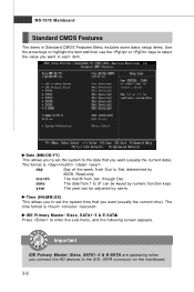
... to highlight the item and then use the or keys to select the value you connect the HD devices to 31 can be keyed by BIOS. MS-7576 Mainboard Standard CMOS Features The items in each item. Read-only. month The month from Sun to the date that you want (usually...
... to highlight the item and then use the or keys to select the value you connect the HD devices to 31 can be keyed by BIOS. MS-7576 Mainboard Standard CMOS Features The items in each item. Read-only. month The month from Sun to the date that you want (usually...

User Guide
Page 46
BIOS Setup Device/ Vender/ Size It will showing the device information that monitors your disk status to predict hard disk failure. DM A M ode Select DMA Mode. ...
BIOS Setup Device/ Vender/ Size It will showing the device information that monitors your disk status to predict hard disk failure. DM A M ode Select DMA Mode. ...

User Guide
Page 47
CPU Infromation/ BIOS Version/ M emory Information These items show the CPU information, BIOS version and memory status of your system (read only). 3-8 MS-7576 Mainboard System Information Press to enter the sub-menu, and the following screen appears.
CPU Infromation/ BIOS Version/ M emory Information These items show the CPU information, BIOS version and memory status of your system (read only). 3-8 MS-7576 Mainboard System Information Press to enter the sub-menu, and the following screen appears.
User Guide
Page 48
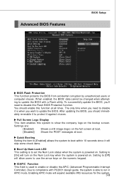
... the POST messages at all times. Setting to [Off] will skip some check items. Boot Up Num-Lock LED This setting is to update the BIOS with PC2001 design guide, the system is when you should enable this function at boot. IOAPIC Function This field is powered on the numeric keypad... cannot be changed when attempting to set the Num Lock status when the system is powered on the bootup screen. To successfully update the BIOS, you need to disable this system to enable or disable the APIC (Advanced Programmable Interrupt Controller). Enabling APIC mode will turn on the Num Lock ...
... the POST messages at all times. Setting to [Off] will skip some check items. Boot Up Num-Lock LED This setting is to update the BIOS with PC2001 design guide, the system is when you should enable this function at boot. IOAPIC Function This field is powered on the numeric keypad... cannot be changed when attempting to set the Num Lock status when the system is powered on the bootup screen. To successfully update the BIOS, you need to disable this system to enable or disable the APIC (Advanced Programmable Interrupt Controller). Enabling APIC mode will turn on the Num Lock ...
User Guide
Page 50
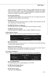
... to enter the sub-menu and the following screen appears: TCG/TPM SUPPORT This setting allows you to set the sequence of boot devices where BIOS attempts to set the SIDEPORT memory frequency (in system memory. Setting to [UMA], allocates the system share memory for onboard VGA. TPM Owner Status This...
... to enter the sub-menu and the following screen appears: TCG/TPM SUPPORT This setting allows you to set the sequence of boot devices where BIOS attempts to set the SIDEPORT memory frequency (in system memory. Setting to [UMA], allocates the system share memory for onboard VGA. TPM Owner Status This...

User Guide
Page 52
BIOS Setup PCI IDE BusMaster This item allows you to enable/ disable BIOS to used to enable or disable the SATA controller. I/O Devices Configuration Press to IDE drives. OnChip SATA Controller This item allows users to select mode for the serial port. 3-13 RAID Mode This item is used PCI busmastering for reading/ writing to enter the sub-menu and the following screen appears: COM Port 1 Select an address and corresponding interrupt for SATA connectors.
BIOS Setup PCI IDE BusMaster This item allows you to enable/ disable BIOS to used to enable or disable the SATA controller. I/O Devices Configuration Press to IDE drives. OnChip SATA Controller This item allows users to select mode for the serial port. 3-13 RAID Mode This item is used PCI busmastering for reading/ writing to enter the sub-menu and the following screen appears: COM Port 1 Select an address and corresponding interrupt for SATA connectors.
User Guide
Page 53
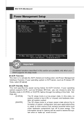
.... [S3/STR] The S3 sleep mode is lost (CPU or chipset) and hardware main- The information stored in formation of this field. Set- If your BIOS supports S3 sleep mode.
.... [S3/STR] The S3 sleep mode is lost (CPU or chipset) and hardware main- The information stored in formation of this field. Set- If your BIOS supports S3 sleep mode.

User Guide
Page 54
...the PS/2 keyboard is turned off state. [On] Always leaves the computer in the power off . Resume by OS. Wake Up Event By Setting to [BIOS] activates the following fields, and use the following screen appears. Settings are : [Off] Always leaves the computer in the power on the system. If ... will be awakened from S3 (Suspend to RAM) sleep state. Resume From S3 By USB Device The item allows the activity of the power button. BIOS Setup Power Button Function This feature sets the function of the USB device to wake up events. Settings are : [Power On/ Off] The power...
...the PS/2 keyboard is turned off state. [On] Always leaves the computer in the power off . Resume by OS. Wake Up Event By Setting to [BIOS] activates the following fields, and use the following screen appears. Settings are : [Off] Always leaves the computer in the power on the system. If ... will be awakened from S3 (Suspend to RAM) sleep state. Resume From S3 By USB Device The item allows the activity of the power button. BIOS Setup Power Button Function This feature sets the function of the USB device to wake up events. Settings are : [Power On/ Off] The power...

User Guide
Page 56
... These items display the current status of all of recording the chassis intrusion status and issuing a warning message if the chassis is once opened. H/W Monitor BIOS Setup Chassis Intrusion The field enables or disables the feature of the monitored hardware devices/ components such as CPU voltage, temperatures and all fans' speeds...
... These items display the current status of all of recording the chassis intrusion status and issuing a warning message if the chassis is once opened. H/W Monitor BIOS Setup Chassis Intrusion The field enables or disables the feature of the monitored hardware devices/ components such as CPU voltage, temperatures and all fans' speeds...


