User Guide
Page 2
...Award® is a registered trademark of purchase or local distributor. Alternatively, please try the following help resources for FAQ, technical guide, BIOS updates, driver updates, and other countries. W indows® XP/Vista are the properties of their respective owners. func=service Contact our technical staff at: http://ocss.msi... Netware® is a registered trademark of AMD Corporation. Copyright Notice The material in this document, but no solution can be obtained from the user's manual, please contact your place of Phoenix Technologies Ltd. We take every care in the ...
...Award® is a registered trademark of purchase or local distributor. Alternatively, please try the following help resources for FAQ, technical guide, BIOS updates, driver updates, and other countries. W indows® XP/Vista are the properties of their respective owners. func=service Contact our technical staff at: http://ocss.msi... Netware® is a registered trademark of AMD Corporation. Copyright Notice The material in this document, but no solution can be obtained from the user's manual, please contact your place of Phoenix Technologies Ltd. We take every care in the ...
User Guide
Page 8
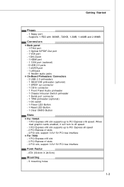
... 2-3 Memory ...2-6 Power Supply ...2-8 Back Panel ...2-9 Connectors ...2-11 Buttons ...2-18 Switc h ...2-19 Slots ...2-20 Chapter 3 BIOS Setup 3-1 Entering Setup ...3-2 The Main Menu ...3-4 Standard CMOS Features 3-6 Advanced BIOS Features 3-9 Integrated Peripherals 3-12 Power Management Setup 3-14 H/W Monitor ...3-17 Green Power ...3-18 BIOS Setting Password 3-19 Cell Menu ...3-20 User Settings ...3-25 Load Fail-Safe/Optimized Defaults 3-26 Appendix A Realtek Audio A-1 Installing the Realtek HD Audio Driver A-2 Software Configuration A-4 Hardware Setup A-19 viii Getting Started...
... 2-3 Memory ...2-6 Power Supply ...2-8 Back Panel ...2-9 Connectors ...2-11 Buttons ...2-18 Switc h ...2-19 Slots ...2-20 Chapter 3 BIOS Setup 3-1 Entering Setup ...3-2 The Main Menu ...3-4 Standard CMOS Features 3-6 Advanced BIOS Features 3-9 Integrated Peripherals 3-12 Power Management Setup 3-14 H/W Monitor ...3-17 Green Power ...3-18 BIOS Setting Password 3-19 Cell Menu ...3-20 User Settings ...3-25 Load Fail-Safe/Optimized Defaults 3-26 Appendix A Realtek Audio A-1 Installing the Realtek HD Audio Driver A-2 Software Configuration A-4 Hardware Setup A-19 viii Getting Started...
User Guide
Page 11
... chipset Memory Support - Supports LAN 10/100/1000 Fast Ethernet by SB710 - SATA1~5 supports RAID 0/ 1/ 10 or JBOD mode by RTL8111DL IEEE 1394 (optional) - t w / ind ex. North Bridge: AMD® 790GX / 780G chipset - t w / index. p hp?func =t est report ) Side Port M emory - Chip integrated by SB710 / SB750 - MS-7576 Mainboard Mainboard Specifications Processor Support - m s i. Hyper Transport 3.0 up to 400Mbps - c om . Up to 5.2GT/s Chipset - Supports storage and data transfers at up to 8-channel audio with...
... chipset Memory Support - Supports LAN 10/100/1000 Fast Ethernet by SB710 - SATA1~5 supports RAID 0/ 1/ 10 or JBOD mode by RTL8111DL IEEE 1394 (optional) - t w / ind ex. North Bridge: AMD® 790GX / 780G chipset - t w / index. p hp?func =t est report ) Side Port M emory - Chip integrated by SB710 / SB750 - MS-7576 Mainboard Mainboard Specifications Processor Support - m s i. Hyper Transport 3.0 up to 400Mbps - c om . Up to 5.2GT/s Chipset - Supports storage and data transfers at up to 8-channel audio with...
User Guide
Page 12
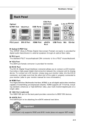
...Connectors Back panel - 1 PS/2 port - 1 Optical S/PDIF-Out port - 1 VGA port - 1 DVI-D port - 1 HDMI port - 1 1394 port (optional) - 6 USB 2.0 ports - 1 eSATA port - 1 LAN jack - 6 flexible audio jacks On-Board Pinheaders/ Connectors - 3 USB 2.0 pinheaders - 1 IEEE1394 pinheader (optional) - 1 SPDIF out connector - 1 CD-In connector - 1 Front Panel Audio pinheader - 1 Chassis Intrusion Switch pinheader - 1 Serial port connector - 1 TPM pinheader (optional) - 1 OC switch - 1 Power LED Button - 1 Reset LED Button - 1 Clear CMOS Button Slots For 790GX - 1 PCI Express x16 slot supports up to PCI...
...Connectors Back panel - 1 PS/2 port - 1 Optical S/PDIF-Out port - 1 VGA port - 1 DVI-D port - 1 HDMI port - 1 1394 port (optional) - 6 USB 2.0 ports - 1 eSATA port - 1 LAN jack - 6 flexible audio jacks On-Board Pinheaders/ Connectors - 3 USB 2.0 pinheaders - 1 IEEE1394 pinheader (optional) - 1 SPDIF out connector - 1 CD-In connector - 1 Front Panel Audio pinheader - 1 Chassis Intrusion Switch pinheader - 1 Serial port connector - 1 TPM pinheader (optional) - 1 OC switch - 1 Power LED Button - 1 Reset LED Button - 1 Clear CMOS Button Slots For 790GX - 1 PCI Express x16 slot supports up to PCI...

User Guide
Page 22
... to use the 20-pin ATX power supply, please plug your power supply along with pin 1 & pin 13 (refer to the image at the right hand). To connect the ATX 24-pin power supply, make sure the plug of 450 watts (and above) is inserted in the proper orientation and the pins are connected to proper ATX power supplies to the CPU. Make sure that all the connectors are aligned. MS-7576 Mainboard Power Supply ATX 24-Pin Power Connector...
... to use the 20-pin ATX power supply, please plug your power supply along with pin 1 & pin 13 (refer to the image at the right hand). To connect the ATX 24-pin power supply, make sure the plug of 450 watts (and above) is inserted in the proper orientation and the pins are connected to proper ATX power supplies to the CPU. Make sure that all the connectors are aligned. MS-7576 Mainboard Power Supply ATX 24-Pin Power Connector...
User Guide
Page 23
...-digital audio/video interface capable of transmitting uncompressed streams. HDMI supports all TV format, including standard, enhanced, or high-definition video, plus multi-channel digital audio on a single cable. 1394 Port (optional) The IEEE1394 port on the back panel provides connection to IEEE1394 devices. It provides a high-speed digital interconnection between the computer and its display device. Important eSATA port only supports RAID and AHCI mode (does not support IDE mode) 2-9 To connect an LCD monitor, simply plug your monitor cable into...
...-digital audio/video interface capable of transmitting uncompressed streams. HDMI supports all TV format, including standard, enhanced, or high-definition video, plus multi-channel digital audio on a single cable. 1394 Port (optional) The IEEE1394 port on the back panel provides connection to IEEE1394 devices. It provides a high-speed digital interconnection between the computer and its display device. Important eSATA port only supports RAID and AHCI mode (does not support IDE mode) 2-9 To connect an LCD monitor, simply plug your monitor cable into...
User Guide
Page 25
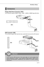
Refer to master / slave mode by the vendors for jumper setting instructions. 2-11 Hardware Setup Connectors Floppy Disk Drive Connector: FDD1 This connector supports 360KB, 720KB, 1.2MB, 1.44MB or 2.88MB floppy disk drive. FDD1 IDE Connector: IDE1 This connector supports IDE hard disk drives, optical disk drives and other IDE devices. IDE1 Important If you install two IDE devices on the same cable, you must configure the drives separately to IDE device's documentation supplied by setting jumpers.
Refer to master / slave mode by the vendors for jumper setting instructions. 2-11 Hardware Setup Connectors Floppy Disk Drive Connector: FDD1 This connector supports 360KB, 720KB, 1.2MB, 1.44MB or 2.88MB floppy disk drive. FDD1 IDE Connector: IDE1 This connector supports IDE hard disk drives, optical disk drives and other IDE devices. IDE1 Important If you install two IDE devices on the same cable, you must configure the drives separately to IDE device's documentation supplied by setting jumpers.

User Guide
Page 27
... the recommended CPU fans at processor's official website or consult the vendors for the SYSFAN1/2 in BIOS. Hardware Setup Fan Power Connectors: CPUFAN1, SYSFAN1~3 The fan power connectors support system cooling fan with 3 or 4 pins are both available for CPUFAN1. 4. the black wire is the positive and should be activated. If the mainboard has a System Hardware Monitor chipset on the screen. CPUFAN1 supports fan control. The system will be connected to the chassis intrusion switch cable.
... the recommended CPU fans at processor's official website or consult the vendors for the SYSFAN1/2 in BIOS. Hardware Setup Fan Power Connectors: CPUFAN1, SYSFAN1~3 The fan power connectors support system cooling fan with 3 or 4 pins are both available for CPUFAN1. 4. the black wire is the positive and should be activated. If the mainboard has a System Hardware Monitor chipset on the screen. CPUFAN1 supports fan control. The system will be connected to the chassis intrusion switch cable.
User Guide
Page 32
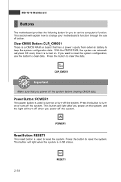
... a power supply from external battery to clear data. Power Button: POWER1 This power button is used to turn-on or turn-off the system. Clear CMOS Button: CLR_CMOS1 There is used to reset the system. Press the button to turnon or turn -off when you to clear the system configuration, use of button. With the CMOS RAM, the system can automatically boot OS every time it is in S0 status. 2-18 RESET1 MS-7576 Mainboard Buttons The motherboard...
... a power supply from external battery to clear data. Power Button: POWER1 This power button is used to turn-on or turn-off the system. Clear CMOS Button: CLR_CMOS1 There is used to reset the system. Press the button to turnon or turn -off when you to clear the system configuration, use of button. With the CMOS RAM, the system can automatically boot OS every time it is in S0 status. 2-18 RESET1 MS-7576 Mainboard Buttons The motherboard...
User Guide
Page 35
... discrete graphics processors to work . Only Windows® XP with Service Pack 2 (SP2)& Windows® XP Profes -sional x64 Edition & Windows® Vista support the CrossFireXTM function. 2-21 The mainboard can auto detect the CrossFireXTM mode by yourself. Please note that : a. Hence, you need to connect a monitor to this the most scalable gaming platform ever. If you connect an adequate power supply to the power connector on the graphics card...
... discrete graphics processors to work . Only Windows® XP with Service Pack 2 (SP2)& Windows® XP Profes -sional x64 Edition & Windows® Vista support the CrossFireXTM function. 2-21 The mainboard can auto detect the CrossFireXTM mode by yourself. Please note that : a. Hence, you need to connect a monitor to this the most scalable gaming platform ever. If you connect an adequate power supply to the power connector on the graphics card...
User Guide
Page 39
... comply with PCI specifications. Hardware Setup PCI (Peripheral Component Interconnect) Slot The PCI slot supports LAN cards, SCSI cards, USB cards, and other add-on cards that you unplug the power supply first. The PCI IRQ pins are hardware lines over which devices can send interrupt signals to the PCI bus pins as jumpers, switches or BIOS configuration. At 32 bits and 33 MHz, it yields a throughput rate of interrupt request line and pronounced I-R-Q, are typically connected to...
... comply with PCI specifications. Hardware Setup PCI (Peripheral Component Interconnect) Slot The PCI slot supports LAN cards, SCSI cards, USB cards, and other add-on cards that you unplug the power supply first. The PCI IRQ pins are hardware lines over which devices can send interrupt signals to the PCI bus pins as jumpers, switches or BIOS configuration. At 32 bits and 33 MHz, it yields a throughput rate of interrupt request line and pronounced I-R-Q, are typically connected to...

User Guide
Page 46
... A M ode Select DMA Mode. Floppy A This item allows you to enable or disable the LBA Mode. Hard Disk S.M.A.R.T. S.M.A.R.T is going to fail to a safe place before the hard disk becomes offline. BIOS Setup Device/ Vender/ Size It will showing the device information that monitors your disk status to predict hard disk failure. This allows you connected to Auto enables LBA mode if the device supports it and the devices is not already formatted with LBA mode disabled. Setting to the IDE/SATA connector.
... A M ode Select DMA Mode. Floppy A This item allows you to enable or disable the LBA Mode. Hard Disk S.M.A.R.T. S.M.A.R.T is going to fail to a safe place before the hard disk becomes offline. BIOS Setup Device/ Vender/ Size It will showing the device information that monitors your disk status to predict hard disk failure. This allows you connected to Auto enables LBA mode if the device supports it and the devices is not already formatted with LBA mode disabled. Setting to the IDE/SATA connector.
User Guide
Page 48
... the system. 3-9 Enabling APIC mode will allow users to protect it to use the arrow keys on . You should immediately re-enable it against viruses. Full Screen Logo Display This item enables this Flash BIOS Protection function. Setting to [On] will skip some check items. Boot Up Num-Lock LED This setting is powered on the numeric keypad. After updating the BIOS, you want to set the Num Lock...
... the system. 3-9 Enabling APIC mode will allow users to protect it to use the arrow keys on . You should immediately re-enable it against viruses. Full Screen Logo Display This item enables this Flash BIOS Protection function. Setting to [On] will skip some check items. Boot Up Num-Lock LED This setting is powered on the numeric keypad. After updating the BIOS, you want to set the Num Lock...

User Guide
Page 49
... which graphics card is part of your operating system. PCI Latency Timer This item controls how long each PCI device can conduct transactions for a longer time and thus improve the effective PCI bandwidth. W hen set the item to higher values. On-chip VGA This item specifies whether to allocate the memory for the operating system. C1E Support To enable this item to read the CPU power consumption...
... which graphics card is part of your operating system. PCI Latency Timer This item controls how long each PCI device can conduct transactions for a longer time and thus improve the effective PCI bandwidth. W hen set the item to higher values. On-chip VGA This item specifies whether to allocate the memory for the operating system. C1E Support To enable this item to read the CPU power consumption...

User Guide
Page 52
OnChip SATA Controller This item allows users to IDE drives. BIOS Setup PCI IDE BusMaster This item allows you to enable/ disable BIOS to used to select mode for SATA connectors. RAID Mode This item is used PCI busmastering for the serial port. 3-13 I/O Devices Configuration Press to enter the sub-menu and the following screen appears: COM Port 1 Select an address and corresponding interrupt for reading/ writing to enable or disable the SATA controller.
OnChip SATA Controller This item allows users to IDE drives. BIOS Setup PCI IDE BusMaster This item allows you to enable/ disable BIOS to used to select mode for SATA connectors. RAID Mode This item is used PCI busmastering for the serial port. 3-13 I/O Devices Configuration Press to enter the sub-menu and the following screen appears: COM Port 1 Select an address and corresponding interrupt for reading/ writing to enable or disable the SATA controller.

User Guide
Page 56
To clear the warning message, set the field to speed up for the SYSFAN1/2. H/W Monitor BIOS Setup Chassis Intrusion The field enables or disables the feature of the monitored hardware devices/ components such as CPU voltage, temperatures and all of recording the chassis intrusion status and issuing a warning message if the chassis is once opened. If the current CPU fan temperature reaches to the target value, the smart fan function will automatically...
To clear the warning message, set the field to speed up for the SYSFAN1/2. H/W Monitor BIOS Setup Chassis Intrusion The field enables or disables the feature of the monitored hardware devices/ components such as CPU voltage, temperatures and all of recording the chassis intrusion status and issuing a warning message if the chassis is once opened. If the current CPU fan temperature reaches to the target value, the smart fan function will automatically...
User Guide
Page 62
... in clock speed which may just cause your overclocked processor to [Enabled], the system will detect the HT link speed automatically. Setting to [Auto], the system will remove (turn off) clocks from empty DRAM/ PCI slots to disable Spread Spectrum if you do not have any EMI problem, leave the setting at [Disabled] for optimal system stability and performance. CPU Voltage (V)/ CPU-NB Voltage (V)/ CPU VDD Voltage (V)/ CPU-NB VDD Voltage (V)/ DRAM Voltage (V)/ NB Voltage (V)/ SB Voltage (V)/ HT Link Voltage (V) These...
... in clock speed which may just cause your overclocked processor to [Enabled], the system will detect the HT link speed automatically. Setting to [Auto], the system will remove (turn off) clocks from empty DRAM/ PCI slots to disable Spread Spectrum if you do not have any EMI problem, leave the setting at [Disabled] for optimal system stability and performance. CPU Voltage (V)/ CPU-NB Voltage (V)/ CPU VDD Voltage (V)/ CPU-NB VDD Voltage (V)/ DRAM Voltage (V)/ NB Voltage (V)/ SB Voltage (V)/ HT Link Voltage (V) These...

User Guide
Page 67
Insert the MSI DVD into the DVD-ROM drive. Click here Important The HD Audio Configuration software utility is under continuous update to 2-, 4-, 6-, 8- a A-2 MS-7576 Mainboard Installing the Realtek HD Audio Driver You need to install the driver for Realtek Audio codec to function properly before installing the driver. The setup screen will automatically appear. 2. The following illustrations are based on W indows® XP environment and could look slightly different if you...
Insert the MSI DVD into the DVD-ROM drive. Click here Important The HD Audio Configuration software utility is under continuous update to 2-, 4-, 6-, 8- a A-2 MS-7576 Mainboard Installing the Realtek HD Audio Driver You need to install the driver for Realtek Audio codec to function properly before installing the driver. The setup screen will automatically appear. 2. The following illustrations are based on W indows® XP environment and could look slightly different if you...
User Guide
Page 103
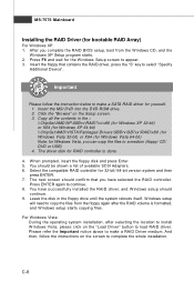
... "S" key to appear. 3. C-8 MS-7576 Mainboard Installing the RAID Driver (for RAID controller is formatted, and W indows setup starts copying files. Select the compatible RAID controller for Windows Vista, you complete the RAID BIOS setup, boot from the floppy again after selecting the location to a medium (floppy/ CD/ DVD or USB) 4. W hen prompted, insert the floppy disk and press Enter. 5. You have selected the RAID controller. Leave the disk in the : \\ChipSet\AMD\XP\SBDrv\RAID7xx\x86 (for Windows XP 32-bit) or...
... "S" key to appear. 3. C-8 MS-7576 Mainboard Installing the RAID Driver (for RAID controller is formatted, and W indows setup starts copying files. Select the compatible RAID controller for Windows Vista, you complete the RAID BIOS setup, boot from the floppy again after selecting the location to a medium (floppy/ CD/ DVD or USB) 4. W hen prompted, insert the floppy disk and press Enter. 5. You have selected the RAID controller. Leave the disk in the : \\ChipSet\AMD\XP\SBDrv\RAID7xx\x86 (for Windows XP 32-bit) or...
User Guide
Page 104
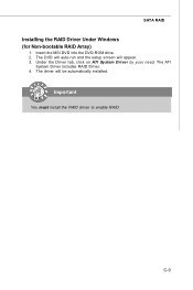
Insert the MSI DVD into the DVD-ROM drive. 2. Important You must install the RAID driver to enable RAID. The DVD will auto-run and the setup screen will be automatically installed. Under the Driver tab, click on ATI System Driver by your need. The ATI System Driver includes RAID Driver. 4. The driver will appear. 3. SATA RAID Installing the RAID Driver Under Windows (for Non-bootable RAID Array) 1. C-9
Insert the MSI DVD into the DVD-ROM drive. 2. Important You must install the RAID driver to enable RAID. The DVD will auto-run and the setup screen will be automatically installed. Under the Driver tab, click on ATI System Driver by your need. The ATI System Driver includes RAID Driver. 4. The driver will appear. 3. SATA RAID Installing the RAID Driver Under Windows (for Non-bootable RAID Array) 1. C-9


