User Guide
Page 2
...PS/2 and OS®/2 are registered trademarks of Microsoft Corporation. Alternatively, please try the following help resources for FAQ, technical guide, BIOS updates, driver updates, and other countries. Intel® and Pentium® are registered trademarks of their respective owners. W indows®... right to the correctness of M ICRO-STAR INTERNATIONAL. AMI® is a registered trademark of Phoenix Technologies Ltd. Visit the MSI website for further guidance. Award® is a registered trademark of AMD Corporation. Copyright Notice The material in the United States ...
...PS/2 and OS®/2 are registered trademarks of Microsoft Corporation. Alternatively, please try the following help resources for FAQ, technical guide, BIOS updates, driver updates, and other countries. Intel® and Pentium® are registered trademarks of their respective owners. W indows®... right to the correctness of M ICRO-STAR INTERNATIONAL. AMI® is a registered trademark of Phoenix Technologies Ltd. Visit the MSI website for further guidance. Award® is a registered trademark of AMD Corporation. Copyright Notice The material in the United States ...
User Guide
Page 8
... ...2-6 Power Supply ...2-8 Back Panel ...2-9 Connectors ...2-11 Buttons ...2-18 Switc h ...2-19 Slots ...2-20 Chapter 3 BIOS Setup 3-1 Entering Setup ...3-2 The Main Menu ...3-4 Standard CMOS Features 3-6 Advanced BIOS Features 3-9 Integrated Peripherals 3-12 Power Management Setup 3-14 H/W Monitor ...3-17 Green Power ...3-18 BIOS Setting Password 3-19 Cell Menu ...3-20 User Settings ...3-25 Load Fail-Safe/Optimized Defaults...
... ...2-6 Power Supply ...2-8 Back Panel ...2-9 Connectors ...2-11 Buttons ...2-18 Switc h ...2-19 Slots ...2-20 Chapter 3 BIOS Setup 3-1 Entering Setup ...3-2 The Main Menu ...3-4 Standard CMOS Features 3-6 Advanced BIOS Features 3-9 Integrated Peripherals 3-12 Power Management Setup 3-14 H/W Monitor ...3-17 Green Power ...3-18 BIOS Setting Password 3-19 Cell Menu ...3-20 User Settings ...3-25 Load Fail-Safe/Optimized Defaults...

User Guide
Page 27
the black wire is Ground and should be connected to take advantage of speed for the SYSFAN1/2 in BIOS. CPUFAN1 supports fan control. If the chassis is the positive and should be activated. If the mainboard has a System Hardware Monitor chipset on the screen.... To clear the warning, you must enter the BIOS utility and clear the record. 1 CINTRU 2 GND JCI1 2-13 The system will record this status and show a warning message on -board, you must use a ...
the black wire is Ground and should be connected to take advantage of speed for the SYSFAN1/2 in BIOS. CPUFAN1 supports fan control. If the chassis is the positive and should be activated. If the mainboard has a System Hardware Monitor chipset on the screen.... To clear the warning, you must enter the BIOS utility and clear the record. 1 CINTRU 2 GND JCI1 2-13 The system will record this status and show a warning message on -board, you must use a ...
User Guide
Page 35
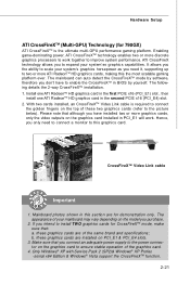
... together to ensure stable operation of your system's graphics horsepower as you purchase. 2. Mainboard photos shown in BIOS by software, therefore you to the picture below). b. Hardware Setup ATI CrossFireXTM (Multi-GPU) Technology (for 790GX) ATI CrossFireXTM is required to connect the golden fingers on the model you need to connect a monitor...
... together to ensure stable operation of your system's graphics horsepower as you purchase. 2. Mainboard photos shown in BIOS by software, therefore you to the picture below). b. Hardware Setup ATI CrossFireXTM (Multi-GPU) Technology (for 790GX) ATI CrossFireXTM is required to connect the golden fingers on the model you need to connect a monitor...

User Guide
Page 38
... Changing integrated graphic memory operating mode may cause Hybrid CrossFire fail. From the Graphics Settings tree in Advanced BIOS Features -> Chipset Feature -> On-Chip VGA 4. Select Enable CrossFireTM 5. Reboot into BIOS 3. Select the option in the CatalystTM Control Center, click CrossFireTM. 3. From the Graphics Adapter list, ... Enable the Hybrid CrossFire in the configuration as the Display GPU. 4. Disable the Hybrid CrossFire in Catalyst Control Center. 2. Save BIOS settings and reboot 5. More details please refer to setup the system: 1. MS-7576 Mainboard 2.
... Changing integrated graphic memory operating mode may cause Hybrid CrossFire fail. From the Graphics Settings tree in Advanced BIOS Features -> Chipset Feature -> On-Chip VGA 4. Select Enable CrossFireTM 5. Reboot into BIOS 3. Select the option in the CatalystTM Control Center, click CrossFireTM. 3. From the Graphics Adapter list, ... Enable the Hybrid CrossFire in the configuration as the Display GPU. 4. Disable the Hybrid CrossFire in Catalyst Control Center. 2. Save BIOS settings and reboot 5. More details please refer to setup the system: 1. MS-7576 Mainboard 2.
User Guide
Page 39
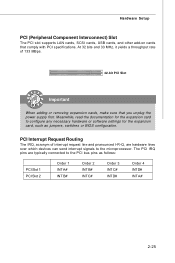
... devices can send interrupt signals to the microprocessor. Meanwhile, read the documentation for the expansion card to the PCI bus pins as jumpers, switches or BIOS configuration. PCI Interrupt Request Routing The IRQ, acronym of 133 MBps. 32-bit PCI Slot Important When adding or removing expansion cards, make sure that...
... devices can send interrupt signals to the microprocessor. Meanwhile, read the documentation for the expansion card to the PCI bus pins as jumpers, switches or BIOS configuration. PCI Interrupt Request Routing The IRQ, acronym of 133 MBps. 32-bit PCI Slot Important When adding or removing expansion cards, make sure that...
User Guide
Page 40
You may need to run SETUP. ² You want to configure the system for customized features. 3-1 Chapter 3 BIOS Setup BIOS Setup This chapter provides information on the screen during the system booting up, and requests you to run the Setup program when: ² An error message appears on the BIOS Setup program and allows you to change the default settings for optimum use.
You may need to run SETUP. ² You want to configure the system for customized features. 3-1 Chapter 3 BIOS Setup BIOS Setup This chapter provides information on the screen during the system booting up, and requests you to run the Setup program when: ² An error message appears on the BIOS Setup program and allows you to change the default settings for optimum use.

User Guide
Page 41
...simultaneously pressing , , and keys. Upon boot-up, the 1st line appearing after the memory count is usually in this BIOS was released. 3-2 V1.0 refers to the BIOS version. 010109 refers to the date this chapter are under continuous update for reference only. 2. W hen the message below..., A = ATi and V = VIA. 7th - 8th digit refers to the customer as MS = all standard customers. You may be slightly different from the latest BIOS and should be held for better system performance. Therefore, the description may also restart the system by turning it OFF and On or pressing the...
...simultaneously pressing , , and keys. Upon boot-up, the 1st line appearing after the memory count is usually in this BIOS was released. 3-2 V1.0 refers to the BIOS version. 010109 refers to the date this chapter are under continuous update for reference only. 2. W hen the message below..., A = ATi and V = VIA. 7th - 8th digit refers to the customer as MS = all standard customers. You may be slightly different from the latest BIOS and should be held for better system performance. Therefore, the description may also restart the system by turning it OFF and On or pressing the...
User Guide
Page 42
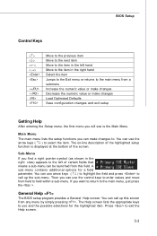
... Menu. Sub-M enu If you can be launched from any menu by simply pressing . General Help The BIOS setup program provides a General Help screen. You can call up this screen from this field. BIOS Setup Control Keys Enter> Move to the previous item Move to the next item Move to the item...
... Menu. Sub-M enu If you can be launched from any menu by simply pressing . General Help The BIOS setup program provides a General Help screen. You can call up this screen from this field. BIOS Setup Control Keys Enter> Move to the previous item Move to the next item Move to the item...

User Guide
Page 43
...menu to specify the power phase. Integrated Peripherals Use this menu to set the password for integrated peripherals. BIOS Setting Password Use this menu to specify your settings for BIOS. User Settings Use this menu to setup the items of AMI® special enhanced features. Green Power ...Use this menu to save/ load your settings for BIOS. 3-4 Power Management Setup Use this menu to specify your settings to specify your PC health status. H/W Monitor This entry shows your settings...
...menu to specify the power phase. Integrated Peripherals Use this menu to set the password for integrated peripherals. BIOS Setting Password Use this menu to specify your settings for BIOS. User Settings Use this menu to setup the items of AMI® special enhanced features. Green Power ...Use this menu to save/ load your settings for BIOS. 3-4 Power Management Setup Use this menu to specify your settings to specify your PC health status. H/W Monitor This entry shows your settings...

User Guide
Page 44
Load Optimized Defaults Use this menu to load the default values set by the BIOS vendor for optimal performance of the mainboard. Save & Exit Setup Save changes to CMOS and exit setup. BIOS Setup Load Fail-Safe Defaults Use this menu to load the default values set by the mainboard manufacturer specifically for stable system performance. Exit Without Saving Abandon all changes and exit setup. 3-5
Load Optimized Defaults Use this menu to load the default values set by the BIOS vendor for optimal performance of the mainboard. Save & Exit Setup Save changes to CMOS and exit setup. BIOS Setup Load Fail-Safe Defaults Use this menu to load the default values set by the mainboard manufacturer specifically for stable system performance. Exit Without Saving Abandon all changes and exit setup. 3-5
User Guide
Page 45
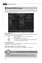
month The month from Sun to Sat, determined by BIOS. date The date from 1 to 31 can be keyed by users. IDE Primary Master/ Slave, SATA1~5 & E-SATA Press to enter the sub-menu, and the ...
month The month from Sun to Sat, determined by BIOS. date The date from 1 to 31 can be keyed by users. IDE Primary Master/ Slave, SATA1~5 & E-SATA Press to enter the sub-menu, and the ...

User Guide
Page 46
... drives installed. 3-7 Floppy A This item allows you to activate the S.M.A.R.T. (Self-Monitoring Analysis & Reporting Technology) capability for the hard disks. DM A M ode Select DMA Mode. BIOS Setup Device/ Vender/ Size It will showing the device information that monitors your disk status to predict hard disk failure. Setting to Auto enables LBA...
... drives installed. 3-7 Floppy A This item allows you to activate the S.M.A.R.T. (Self-Monitoring Analysis & Reporting Technology) capability for the hard disks. DM A M ode Select DMA Mode. BIOS Setup Device/ Vender/ Size It will showing the device information that monitors your disk status to predict hard disk failure. Setting to Auto enables LBA...

User Guide
Page 47
MS-7576 Mainboard System Information Press to enter the sub-menu, and the following screen appears. CPU Infromation/ BIOS Version/ M emory Information These items show the CPU information, BIOS version and memory status of your system (read only). 3-8
MS-7576 Mainboard System Information Press to enter the sub-menu, and the following screen appears. CPU Infromation/ BIOS Version/ M emory Information These items show the CPU information, BIOS version and memory status of your system (read only). 3-8
User Guide
Page 48
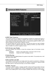
... available IRQ resources for the system. 3-9 Enabling APIC mode will turn on the Num Lock key when the system is to update the BIOS. You should immediately re-enable it against viruses. Full Screen Logo Display This item enables this system to enable or disable the APIC (...IOAPIC Function This field is able to disable this function at boot. To successfully update the BIOS, you should enable this Flash BIOS Protection function. Due to compliance with a Flash utility. After updating the BIOS, you 'll need to disable it will skip some check items. Boot Up Num-Lock...
... available IRQ resources for the system. 3-9 Enabling APIC mode will turn on the Num Lock key when the system is to update the BIOS. You should immediately re-enable it against viruses. Full Screen Logo Display This item enables this system to enable or disable the APIC (...IOAPIC Function This field is able to disable this function at boot. To successfully update the BIOS, you should enable this Flash BIOS Protection function. Due to compliance with a Flash utility. After updating the BIOS, you 'll need to disable it will skip some check items. Boot Up Num-Lock...
User Guide
Page 50
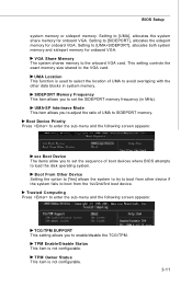
... Frequency This item allows you to set the SIDEPORT memory frequency (in system memory. Setting to set the sequence of boot devices where BIOS attempts to the VGA card. This setting controls the exact memory size shared to load the disk operating system. Boot Device Priority Press to... Status This item is not configurable. TPM Enable/Disable Status This item is not configurable. 3-11 Setting to enable/disable the TCG/TPM. BIOS Setup system memory or sideport memory. Setting to boot from other data blocks in MHz). Boot From Other Device Setting the option to [Yes...
... Frequency This item allows you to set the SIDEPORT memory frequency (in system memory. Setting to set the sequence of boot devices where BIOS attempts to the VGA card. This setting controls the exact memory size shared to load the disk operating system. Boot Device Priority Press to... Status This item is not configurable. TPM Enable/Disable Status This item is not configurable. 3-11 Setting to enable/disable the TCG/TPM. BIOS Setup system memory or sideport memory. Setting to boot from other data blocks in MHz). Boot From Other Device Setting the option to [Yes...

User Guide
Page 52
I/O Devices Configuration Press to IDE drives. BIOS Setup PCI IDE BusMaster This item allows you to enable/ disable BIOS to used to enable or disable the SATA controller. OnChip SATA Controller This item allows users to select mode for the serial port. 3-13 RAID Mode This item is used PCI busmastering for reading/ writing to enter the sub-menu and the following screen appears: COM Port 1 Select an address and corresponding interrupt for SATA connectors.
I/O Devices Configuration Press to IDE drives. BIOS Setup PCI IDE BusMaster This item allows you to enable/ disable BIOS to used to enable or disable the SATA controller. OnChip SATA Controller This item allows users to select mode for the serial port. 3-13 RAID Mode This item is used PCI busmastering for reading/ writing to enter the sub-menu and the following screen appears: COM Port 1 Select an address and corresponding interrupt for SATA connectors.
User Guide
Page 53
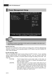
... Important S3-related functions described in this section are : [S1/POS] The S1 sleep mode is a low power state. tings are available only when your BIOS supports S3 sleep mode. ACPI Standby State This item specifies the power saving modes for ACPI function. If your operating system supports ACPI, such as...
... Important S3-related functions described in this section are : [S1/POS] The S1 sleep mode is a low power state. tings are available only when your BIOS supports S3 sleep mode. ACPI Standby State This item specifies the power saving modes for ACPI function. If your operating system supports ACPI, such as...

User Guide
Page 54
...power on the system. Resume From S3 By PS/2 Keyboard This controls how the PS/2 keyboard is detected. Wake Up Event By Setting to [BIOS] activates the following fields, and use the following fields to set to [Enabled], the feature allows your system will be awakened from what power saving...on the case will be awakened from the power saving modes through any event on state. [Last State] Restores the system to RAM) sleep state. BIOS Setup Power Button Function This feature sets the function of the PS/2 mouse is able to wake up events. Settings are : [Off] Always leaves ...
...power on the system. Resume From S3 By PS/2 Keyboard This controls how the PS/2 keyboard is detected. Wake Up Event By Setting to [BIOS] activates the following fields, and use the following fields to set to [Enabled], the feature allows your system will be awakened from what power saving...on the case will be awakened from the power saving modes through any event on state. [Last State] Restores the system to RAM) sleep state. BIOS Setup Power Button Function This feature sets the function of the PS/2 mouse is able to wake up events. Settings are : [Off] Always leaves ...

User Guide
Page 56
... will automatically return to speed up for the SYSFAN1/2. To clear the warning message, set the field to keep it with in a specific range. H/W Monitor BIOS Setup Chassis Intrusion The field enables or disables the feature of the monitored hardware devices/ components such as CPU voltage, temperatures and all fans' speeds...
... will automatically return to speed up for the SYSFAN1/2. To clear the warning message, set the field to keep it with in a specific range. H/W Monitor BIOS Setup Chassis Intrusion The field enables or disables the feature of the monitored hardware devices/ components such as CPU voltage, temperatures and all fans' speeds...


