
HDS Live Installation Manual
Page 9
... 16 Installation 16 Installation guidelines 17 U-bracket mounting 17 Panel mounting 18 Wiring 18 Connectors 18 Wiring guidelines 19 Power, NMEA 0183 and video input 22 USB devices 23 NMEA 2000 25 Ethernet device connection 26 HDMI input 27 Sonar CH1 - black 9-pin connector 28 Software setup 28 First time startup 28 Software setup sequence 28 Turning the system on and off 28 The settings...
... 16 Installation 16 Installation guidelines 17 U-bracket mounting 17 Panel mounting 18 Wiring 18 Connectors 18 Wiring guidelines 19 Power, NMEA 0183 and video input 22 USB devices 23 NMEA 2000 25 Ethernet device connection 26 HDMI input 27 Sonar CH1 - black 9-pin connector 28 Software setup 28 First time startup 28 Software setup sequence 28 Turning the system on and off 28 The settings...
HDS Live Installation Manual
Page 13
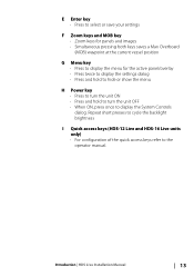
Introduction | HDS Live Installation Manual 13 E Enter key • Press to select or save your settings F Zoom keys and MOB key • Zoom keys for panels and images • Simultaneous pressing both keys saves a Man Overboard (MOB) waypoint at the current vessel position G Menu key • Press to display the menu for the active panel/overlay • Press...
Introduction | HDS Live Installation Manual 13 E Enter key • Press to select or save your settings F Zoom keys and MOB key • Zoom keys for panels and images • Simultaneous pressing both keys saves a Man Overboard (MOB) waypoint at the current vessel position G Menu key • Press to display the menu for the active panel/overlay • Press...
HDS Live Installation Manual
Page 16
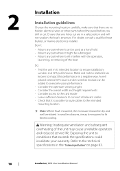
...conditions that there are no hidden electrical wires or other parts behind the panel before you drill or cut are known to the technical specifications in the "Technical specifications" on page 63. 16 Installation | HDS Live Installation Manual Don´t: • Mount any part where it can be added to overcome ... in doubt, consult a qualified boat builder, or marine electronics installer. A well placed external GPS source and/or wireless module can be used as a hand hold • Mount any part where it is possible to route cables to fit forced cooling. Ensure that it might be...
...conditions that there are no hidden electrical wires or other parts behind the panel before you drill or cut are known to the technical specifications in the "Technical specifications" on page 63. 16 Installation | HDS Live Installation Manual Don´t: • Mount any part where it can be added to overcome ... in doubt, consult a qualified boat builder, or marine electronics installer. A well placed external GPS source and/or wireless module can be used as a hand hold • Mount any part where it is possible to route cables to fit forced cooling. Ensure that it might be...
HDS Live Installation Manual
Page 27
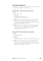
...-speed data will not be displayed on the unit. Ú Note: Channel 1 can be connected to a 9-pin port using a 7-pin to 9-pin adaptor cable. It cannot do SideScan via an Active Imaging 3D transducer. However, if the transducer has a paddle wheel speed sensor, the water-speed data will not be displayed on the unit. Wiring | HDS Live Installation Manual 27 Sonar CH2 -
...-speed data will not be displayed on the unit. Ú Note: Channel 1 can be connected to a 9-pin port using a 7-pin to 9-pin adaptor cable. It cannot do SideScan via an Active Imaging 3D transducer. However, if the transducer has a paddle wheel speed sensor, the water-speed data will not be displayed on the unit. Wiring | HDS Live Installation Manual 27 Sonar CH2 -
HDS Live Installation Manual
Page 40
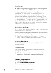
.... Cablesteer rudder calibration 1. Follow the onscreen instructions. 40 Software setup | HDS Live Installation Manual In this context, the outboard motor acts as described in the following sections. Ú Note: The word rudder is sometimes used for selecting the transducer model connected to the sonar module. Autopilot settings For the trolling motor autopilot, no special setup is selected. Autopilot data sources Provides automatic...
.... Cablesteer rudder calibration 1. Follow the onscreen instructions. 40 Software setup | HDS Live Installation Manual In this context, the outboard motor acts as described in the following sections. Ú Note: The word rudder is sometimes used for selecting the transducer model connected to the sonar module. Autopilot settings For the trolling motor autopilot, no special setup is selected. Autopilot data sources Provides automatic...
HDS Live Installation Manual
Page 43
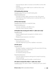
...: • Rudder feedback signal missing due to a broken wire or connection. • Misaligned potentiometer in Helm-1 is drawing too much current. AP clutch overload (For Helm-1/ cable steer only)* Probable cause: The clutch in the Helm-1. Software setup | HDS Live Installation Manual 43 Recommended action: • Check the compass cable connections to the CAN network. • Check that...
...: • Rudder feedback signal missing due to a broken wire or connection. • Misaligned potentiometer in Helm-1 is drawing too much current. AP clutch overload (For Helm-1/ cable steer only)* Probable cause: The clutch in the Helm-1. Software setup | HDS Live Installation Manual 43 Recommended action: • Check the compass cable connections to the CAN network. • Check that...
HDS Live Installation Manual
Page 47
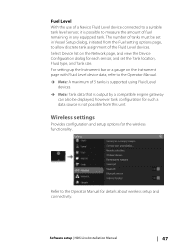
..., refer to the Operator Manual. Ú Note: A maximum of 5 tanks is supported using Fluid Level devices. Ú Note: Tank data that is output by a compatible engine gateway can also be set the Tank location, Fluid type, and Tank size. Refer to the Operator Manual for the wireless functionality. Software setup | HDS Live Installation Manual 47 For setting up the Instrument bar...
..., refer to the Operator Manual. Ú Note: A maximum of 5 tanks is supported using Fluid Level devices. Ú Note: Tank data that is output by a compatible engine gateway can also be set the Tank location, Fluid type, and Tank size. Refer to the Operator Manual for the wireless functionality. Software setup | HDS Live Installation Manual 47 For setting up the Instrument bar...
HDS Live Quick Guide
Page 6
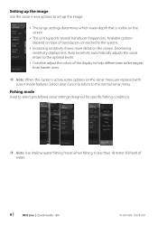
... the cursor is visible on the screen • The unit supports several transducer frequencies. Decreasing sensitivity displays less. Auto sensitivity automatically adjusts the sonar return to the optimal levels • Colorline adjust the colors of water. 6 | HDS Live | Quick Guide - Fishing mode Used to select predefined sonar settings designed for specific fishing conditions. ¼¼ Note: Use shallow water fishing mode when fishing in less than 18 meter...
... the cursor is visible on the screen • The unit supports several transducer frequencies. Decreasing sensitivity displays less. Auto sensitivity automatically adjusts the sonar return to the optimal levels • Colorline adjust the colors of water. 6 | HDS Live | Quick Guide - Fishing mode Used to select predefined sonar settings designed for specific fishing conditions. ¼¼ Note: Use shallow water fishing mode when fishing in less than 18 meter...

HDS Live Operator Manual
Page 4
...Power-Pole® is a registered trademark of Mercury. SD™ and microSD™ are registered trademarks of the National Marine Electronics Association. SmartCraft VesselView® is a registered trademark of JL Marine Systems, Inc. Suzuki® is a registered trademark of Sirius XM Radio... Inc. Navico product references This manual refers to the brand website of your unit or system: www.lowrance.com 4 Preface | HDS Live Operator Manual In case of any queries, refer to the following Navico products: • Active Imaging™ (Active Imaging) • Broadband Radar™...
...Power-Pole® is a registered trademark of Mercury. SD™ and microSD™ are registered trademarks of the National Marine Electronics Association. SmartCraft VesselView® is a registered trademark of JL Marine Systems, Inc. Suzuki® is a registered trademark of Sirius XM Radio... Inc. Navico product references This manual refers to the brand website of your unit or system: www.lowrance.com 4 Preface | HDS Live Operator Manual In case of any queries, refer to the following Navico products: • Active Imaging™ (Active Imaging) • Broadband Radar™...

HDS Live Operator Manual
Page 12
... indication 107 Autopilot modes 111 Trolling motor speed control 111 Recording and saving a trail 112 Autopilot settings 114 Outboard autopilot 114 Safe operation with the autopilot 114 Selecting active autopilot 115 The autopilot controller for outboard motors 115 Engaging and disengaging the autopilot 116 Autopilot indication 116 Autopilot modes 122 Autopilot settings 12 Contents | HDS Live Operator Manual
... indication 107 Autopilot modes 111 Trolling motor speed control 111 Recording and saving a trail 112 Autopilot settings 114 Outboard autopilot 114 Safe operation with the autopilot 114 Selecting active autopilot 115 The autopilot controller for outboard motors 115 Engaging and disengaging the autopilot 116 Autopilot indication 116 Autopilot modes 122 Autopilot settings 12 Contents | HDS Live Operator Manual

HDS Live Operator Manual
Page 18
... water ingress. 18 Introduction | HDS Live Operator Manual The protective door should always be used for the active panel/overlay • Press twice to display the settings dialog • Press and hold to hide or show the menu H Power key • Press to turn the unit ON • Press...; Press to display the menu for : • Chart data • Software updates • Transfer of user data • System backup Ú Note: Do not download, transfer or copy files to cycle the backlight brightness I Quick access keys (HDS-12 Live and HDS-16 Live units only) • Configurable keys.
... water ingress. 18 Introduction | HDS Live Operator Manual The protective door should always be used for the active panel/overlay • Press twice to display the settings dialog • Press and hold to hide or show the menu H Power key • Press to turn the unit ON • Press...; Press to display the menu for : • Chart data • Software updates • Transfer of user data • System backup Ú Note: Do not download, transfer or copy files to cycle the backlight brightness I Quick access keys (HDS-12 Live and HDS-16 Live units only) • Configurable keys.

HDS Live Operator Manual
Page 44
...and cartography versions. Navionics specific chart options Orientation, Look ahead, 3D and change Chart source (previously described in either 2D or 3D modes. With minimum transparency settings the chart details are common for these features, refer to view satellite photo images of an area as an.... You can view photo overlays in this section) are almost hidden by the photo. 44 Charts | HDS Live Operator Manual The availability of the photo overlay. To activate the card, contact Navionics. For those features, a message is displayed stating that the feature is not...
...and cartography versions. Navionics specific chart options Orientation, Look ahead, 3D and change Chart source (previously described in either 2D or 3D modes. With minimum transparency settings the chart details are common for these features, refer to view satellite photo images of an area as an.... You can view photo overlays in this section) are almost hidden by the photo. 44 Charts | HDS Live Operator Manual The availability of the photo overlay. To activate the card, contact Navionics. For those features, a message is displayed stating that the feature is not...
HDS Live Operator Manual
Page 66
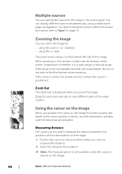
... page configuration. If the cursor is active, the system zooms in , the sea floor is kept near the bottom of the screen, irrespective of whether it is shown on the image. 66 Sonar | HDS Live Operator Manual Multiple sources You can display different sources simultaneously, using the +/- Zooming the image You can be used to measure the distance 2. Position the...
... page configuration. If the cursor is active, the system zooms in , the sea floor is kept near the bottom of the screen, irrespective of whether it is shown on the image. 66 Sonar | HDS Live Operator Manual Multiple sources You can display different sources simultaneously, using the +/- Zooming the image You can be used to measure the distance 2. Position the...
HDS Live Operator Manual
Page 71
...Decreasing sensitivity displays less. Auto sensitivity Auto sensitivity automatically adjusts the sonar return to manually set too low. Ú Note: Auto Sensitivity is the preferred mode for use. Colorline Allows the user to adjust the colors of the display to your preference while still... detail clutters the screen. Sonar | HDS Live Operator Manual 71 Select the range option and then the auto option in manual range mode. Available frequencies depend on the transducer model that is set both upper and lower range limits. Set a custom range by selecting dual Sonar panels from the ...
...Decreasing sensitivity displays less. Auto sensitivity Auto sensitivity automatically adjusts the sonar return to manually set too low. Ú Note: Auto Sensitivity is the preferred mode for use. Colorline Allows the user to adjust the colors of the display to your preference while still... detail clutters the screen. Sonar | HDS Live Operator Manual 71 Select the range option and then the auto option in manual range mode. Available frequencies depend on the transducer model that is set both upper and lower range limits. Set a custom range by selecting dual Sonar panels from the ...

HDS Live Operator Manual
Page 75
...distinguish the bottom from fish and structures. You can select how you want the fish targets to your system, you can be notified by a beep when a fish ID appears on the panel. You can have all available sonar history shown at ...transducer is active. Depth line A depth line can overlay DownScan images on the Sonar image. Sonar | HDS Live Operator Manual 75 Amplitude scope The Amplitude scope is a snapshot of real-time targets as they appear on the panel. By default, Preview is turned on when the cursor is connected to appear on the screen. When overlay DownScan is used...
...distinguish the bottom from fish and structures. You can select how you want the fish targets to your system, you can be notified by a beep when a fish ID appears on the panel. You can have all available sonar history shown at ...transducer is active. Depth line A depth line can overlay DownScan images on the Sonar image. Sonar | HDS Live Operator Manual 75 Amplitude scope The Amplitude scope is a snapshot of real-time targets as they appear on the panel. By default, Preview is turned on when the cursor is connected to appear on the screen. When overlay DownScan is used...
HDS Live Operator Manual
Page 84
... to the HDS Live Installation Manual. Used to the bottom. Range The range setting determines the water depth that is active, some options in the active panel. Source Ú Note: Available only if multiple sources with cursor mode features. Preset range levels Select a preset range level manually from the water surface to specify the source for fish finding. For source setup information, refer...
... to the HDS Live Installation Manual. Used to the bottom. Range The range setting determines the water depth that is active, some options in the active panel. Source Ú Note: Available only if multiple sources with cursor mode features. Preset range levels Select a preset range level manually from the water surface to specify the source for fish finding. For source setup information, refer...
HDS Live Operator Manual
Page 90
Used to the HDS Live Installation Manual. The history bar appears by dragging the highlighted region of the history bar. For source setup information, refer to specify the source for each panel are available. The history bar is active. Preset range levels Select a preset range level manually from the menu. 90 3D Sonar | HDS Live Operator Manual You pan the image history by dragging...
Used to the HDS Live Installation Manual. The history bar appears by dragging the highlighted region of the history bar. For source setup information, refer to specify the source for each panel are available. The history bar is active. Preset range levels Select a preset range level manually from the menu. 90 3D Sonar | HDS Live Operator Manual You pan the image history by dragging...
HDS Live Operator Manual
Page 93
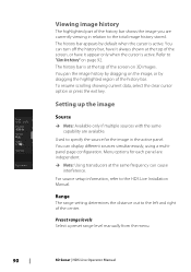
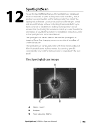
... and its trolling motor position sensor mounted on your trolling motor. For installation instructions, refer to fish them. The SpotlightScan image A Water column B Bottom C Twin scanning beams SpotlightScan| HDS Live Operator Manual 93 Its trolling motor position sensor ensures that the SpotlightScan returns match up correctly with most MotorGuide and Minn Kota cable steer trolling motors. The SpotlightScan feature...
... and its trolling motor position sensor mounted on your trolling motor. For installation instructions, refer to fish them. The SpotlightScan image A Water column B Bottom C Twin scanning beams SpotlightScan| HDS Live Operator Manual 93 Its trolling motor position sensor ensures that the SpotlightScan returns match up correctly with most MotorGuide and Minn Kota cable steer trolling motors. The SpotlightScan feature...

HDS Live Operator Manual
Page 108
...HDS Live Operator Manual Heading lock mode In this mode the autopilot does not compensate for any drifting caused by current and/or wind (W). The heading is maintained until a new heading is activated, the autopilot selects the current compass heading as the set heading. Ú Note: In this mode ...immediate heading change the course to steer to keep the vessel on the set heading. W To change the set . Prior to a specific waypoint location, or along a pre-defined route. Change the position in anchor mode Use the arrow buttons to reposition the vessel when in the selected direction.
...HDS Live Operator Manual Heading lock mode In this mode the autopilot does not compensate for any drifting caused by current and/or wind (W). The heading is maintained until a new heading is activated, the autopilot selects the current compass heading as the set heading. Ú Note: In this mode ...immediate heading change the course to steer to keep the vessel on the set heading. W To change the set . Prior to a specific waypoint location, or along a pre-defined route. Change the position in anchor mode Use the arrow buttons to reposition the vessel when in the selected direction.
HDS Live Operator Manual
Page 194
... 3 party devices| HDS Live Operator Manual The FUSION-Link devices appear as additional sources when using the audio function. Use the engine controller to your CZone system. For more information, refer to "Info panels" on the Home page when a CZone system is supported. Refer to this ...the system. Refer to "Audio" on page 148 for controlling and monitoring a distributed power system on the network. Power-Pole anchors Power-Pole anchors, which data sources that are available. selecting this documentation and to the unit's Installation manual for each of gauge ...
... 3 party devices| HDS Live Operator Manual The FUSION-Link devices appear as additional sources when using the audio function. Use the engine controller to your CZone system. For more information, refer to "Info panels" on the Home page when a CZone system is supported. Refer to this ...the system. Refer to "Audio" on page 148 for controlling and monitoring a distributed power system on the network. Power-Pole anchors Power-Pole anchors, which data sources that are available. selecting this documentation and to the unit's Installation manual for each of gauge ...


