
Operators Manual US
Page 3
... injury or property damage. Fishing Hot Spots® is a registered trademark of the Documentation. Preface | HDS Gen3 Operator Manual 3 It is the owner's sole responsibility to install and use the equipment in this product is a registered trademark of Fishing Hot Spots Inc. Governing ... 2012 Fishing Hot Spots. SiriusXM® is solely responsible for observing safe boating practices. FUSION-LinkTM Marine Entertainment StandardTM is a registered trademark of this version of Navico. Please contact your nearest distributor if you require any instruction manuals, user guides and ...
... injury or property damage. Fishing Hot Spots® is a registered trademark of the Documentation. Preface | HDS Gen3 Operator Manual 3 It is the owner's sole responsibility to install and use the equipment in this product is a registered trademark of Fishing Hot Spots Inc. Governing ... 2012 Fishing Hot Spots. SiriusXM® is solely responsible for observing safe boating practices. FUSION-LinkTM Marine Entertainment StandardTM is a registered trademark of this version of Navico. Please contact your nearest distributor if you require any instruction manuals, user guides and ...

Operators Manual US
Page 21
... is operated by the system. This manual does not include specific operation instructions for how to "Audio" on the NMEA 2000 network. FUSION-Link integration The FUSION-Link devices appear as additional sources when using menus and dialogs as on other panels. No additional icons are enabled through the HDS Gen3 when a VesselView 7 or VesselView 4 gateway device...
... is operated by the system. This manual does not include specific operation instructions for how to "Audio" on the NMEA 2000 network. FUSION-Link integration The FUSION-Link devices appear as additional sources when using menus and dialogs as on other panels. No additional icons are enabled through the HDS Gen3 when a VesselView 7 or VesselView 4 gateway device...

Operators Manual US
Page 64
... "Sonar Settings" on the Sonar image; When zooming in, the sea floor is kept near the bottom of the screen, irrespective of the panel. keys Zoom level is shown, and the information window and the history bar are currently viewing in relation to the total Sonar image history stored. 64 Sonar | HDS Gen3 Operator Manual the screen pauses, the depth at...
... "Sonar Settings" on the Sonar image; When zooming in, the sea floor is kept near the bottom of the screen, irrespective of the panel. keys Zoom level is shown, and the information window and the history bar are currently viewing in relation to the total Sonar image history stored. 64 Sonar | HDS Gen3 Operator Manual the screen pauses, the depth at...

Operators Manual US
Page 65
... is set up the Sonar image Use the Sonar menu options to set to the normal Sonar menu. Sonar | HDS Gen3 Operator Manual 65 The range The range setting determines the water depth that you position the cursor to the left side of the screen, the history bar starts scrolling towards the left, and the automatic scrolling as new soundings are received is turned...
... is set up the Sonar image Use the Sonar menu options to set to the normal Sonar menu. Sonar | HDS Gen3 Operator Manual 65 The range The range setting determines the water depth that you position the cursor to the left side of the screen, the history bar starts scrolling towards the left, and the automatic scrolling as new soundings are received is turned...

Operators Manual US
Page 81
...HDS Gen3 Operator Manual 81 Its scanning speed is controlled by how fast the trolling motor is rotated with most MotorGuide and Minn Kota cable steer trolling motors. The SpotlightScan transducer can show structure and fish targets ahead and around the boat without disturbing these areas before you have a chance to the SpotlightScan Installation Manual. The SpotlightScan transducer...its trolling motor position sensor mounted on the trolling motor foot pedal. 9 SpotlightScan To use the SpotlightScan feature, the SpotlightScan transducer must be used for SpotlightScan imaging, Downscan ...
...HDS Gen3 Operator Manual 81 Its scanning speed is controlled by how fast the trolling motor is rotated with most MotorGuide and Minn Kota cable steer trolling motors. The SpotlightScan transducer can show structure and fish targets ahead and around the boat without disturbing these areas before you have a chance to the SpotlightScan Installation Manual. The SpotlightScan transducer...its trolling motor position sensor mounted on the trolling motor foot pedal. 9 SpotlightScan To use the SpotlightScan feature, the SpotlightScan transducer must be used for SpotlightScan imaging, Downscan ...
Operators Manual US
Page 97
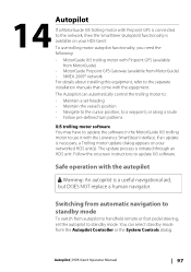
...: An autopilot is initiated through an HDS unit. If an update is available on your HDS Gen3. 14 Autopilot If a MotorGuide Xi5 trolling motor with the Lowrance SmartSteer interface. Follow the onscreen instructions to the separate installation manuals that come with the equipment. Safe operation with Pinpoint GPS (available from MotorGuide) • MotorGuide Pinpoint GPS Gateway (available from MotorGuide) •...
...: An autopilot is initiated through an HDS unit. If an update is available on your HDS Gen3. 14 Autopilot If a MotorGuide Xi5 trolling motor with the Lowrance SmartSteer interface. Follow the onscreen instructions to the separate installation manuals that come with the equipment. Safe operation with Pinpoint GPS (available from MotorGuide) • MotorGuide Pinpoint GPS Gateway (available from MotorGuide) •...
Operators Manual US
Page 150
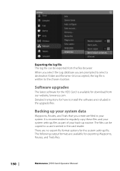
... | HDS Gen3 Operator Manual Software upgrades The latest software for download from the files browser. Backing up routine. Once accepted, the log file is available for the HDS Gen3 is written to install the software are prompted to a card inserted in the card reader. It is recommended to regularly copy these files and your system settings files as part...
... | HDS Gen3 Operator Manual Software upgrades The latest software for download from the files browser. Backing up routine. Once accepted, the log file is available for the HDS Gen3 is written to install the software are prompted to a card inserted in the card reader. It is recommended to regularly copy these files and your system settings files as part...
Installation Manual US
Page 3
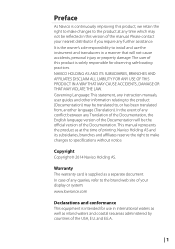
...this product, we retain the right to make changes to specifications without notice. The user of the Documentation. This manual represents the product as at any instruction manuals, user guides and other information relating to the product (Documentation) may ...install and use in international waters as well as a separate document. Please contact your display or system: www.lowrance.com Declarations and conformance This equipment is intended for observing safe boating practices. It is solely responsible for use the instrument and transducers in this product is the owner...
...this product, we retain the right to make changes to specifications without notice. The user of the Documentation. This manual represents the product as at any instruction manuals, user guides and other information relating to the product (Documentation) may ...install and use in international waters as well as a separate document. Please contact your display or system: www.lowrance.com Declarations and conformance This equipment is intended for observing safe boating practices. It is solely responsible for use the instrument and transducers in this product is the owner...
Installation Manual US
Page 5
... harmful interference to radio or television reception, which can radiate radio frequency energy and, if not installed and used in accordance with the instructions, may cause harmful interference to correct the interference by turning the equipment off and on a circuit different from that the interference will not occur in a residential installation. This equipment generates, uses and can be...
... harmful interference to radio or television reception, which can radiate radio frequency energy and, if not installed and used in accordance with the instructions, may cause harmful interference to correct the interference by turning the equipment off and on a circuit different from that the interference will not occur in a residential installation. This equipment generates, uses and can be...

Installation Manual US
Page 7
...' is being used under license. | 5 The manual does not cover basic background information about how equipment such as follows: Note: Used to draw the reader's attention to equipment/personnel. Warning: Used when it is necessary to warn personnel that requires special attention from the reader is a reference guide for installing the Lowrance HDS-7, HDS-9, and HDS-12 Gen3 displays. Important...
...' is being used under license. | 5 The manual does not cover basic background information about how equipment such as follows: Note: Used to draw the reader's attention to equipment/personnel. Warning: Used when it is necessary to warn personnel that requires special attention from the reader is a reference guide for installing the Lowrance HDS-7, HDS-9, and HDS-12 Gen3 displays. Important...

Installation Manual US
Page 10
.... The displays are charting ready, with the supplied surface mount bracket, or flush mounted in DC systems. 8 | HDS Gen3 overview | HDS Gen3 Installation Manual All displays are intended for Insight, Navionics®, and C-MAP™ cartography. 1 HDS Gen3 overview All HDS-7, HDS-9, and HDS-12 Gen3 multifunction displays have built-in high speed GPS receiver (10Hz) and support for 12 V DC operation, though will accept the moderate...
.... The displays are charting ready, with the supplied surface mount bracket, or flush mounted in DC systems. 8 | HDS Gen3 overview | HDS Gen3 Installation Manual All displays are intended for Insight, Navionics®, and C-MAP™ cartography. 1 HDS Gen3 overview All HDS-7, HDS-9, and HDS-12 Gen3 multifunction displays have built-in high speed GPS receiver (10Hz) and support for 12 V DC operation, though will accept the moderate...
Installation Manual US
Page 14
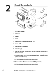
2 Check the contents 2 1 3 6 11 7 8 12 4 9 5 10 13 1 HDS Gen3 display 2 Suncover 3 Bracket 4 Knobs 5 Fasteners (4 x 6G x 1.5 panhead PH1) 6 Power cable 7 Fuse holder (ATC blade) 8 Fuse (3 amp) 9 Caps (3x for HDS7 4x for ethernet, NMEA 2000, StructureScan) 10Documentation pack (Operator & Installation manual, Quick guide, warranty card) 11 83/200 kHz transducer (model dependant) 12StructureScan HD transducer (model dependant) 1350/200 kHz transducer (model dependant) 12 | Check the contents | HDS Gen3 Installation Manual for HDS9/12 -
2 Check the contents 2 1 3 6 11 7 8 12 4 9 5 10 13 1 HDS Gen3 display 2 Suncover 3 Bracket 4 Knobs 5 Fasteners (4 x 6G x 1.5 panhead PH1) 6 Power cable 7 Fuse holder (ATC blade) 8 Fuse (3 amp) 9 Caps (3x for HDS7 4x for ethernet, NMEA 2000, StructureScan) 10Documentation pack (Operator & Installation manual, Quick guide, warranty card) 11 83/200 kHz transducer (model dependant) 12StructureScan HD transducer (model dependant) 1350/200 kHz transducer (model dependant) 12 | Check the contents | HDS Gen3 Installation Manual for HDS9/12 -

Installation Manual US
Page 15
...Installation | HDS Gen3 Installation Manual | 13 Be sure to connect all of the cables. Inadequate ventilation may affect the internal GPS receiver. ear muffs, protective glasses, gloves and a dust mask. Lowrance displays are high-contrast, and are in a safe position and will not be used in doubt, consult a qualified boat builder, or marine electronics installer... please see the display screen. If bracket mounting the display, choose an area where the display will not weaken the boat's structure. The chosen location should be mounted so that any part where it can be subjected...
...Installation | HDS Gen3 Installation Manual | 13 Be sure to connect all of the cables. Inadequate ventilation may affect the internal GPS receiver. ear muffs, protective glasses, gloves and a dust mask. Lowrance displays are high-contrast, and are in a safe position and will not be used in doubt, consult a qualified boat builder, or marine electronics installer... please see the display screen. If bracket mounting the display, choose an area where the display will not weaken the boat's structure. The chosen location should be mounted so that any part where it can be subjected...

Installation Manual US
Page 21
... turn electrical power off. 5 Wiring Guidelines Don't do this Do make sharp bends in the cables Don't run cables in a way that the voltage of 12 V DC, it is left on or turned on during the installation, fire, electrical shock, or other serious injury may occur. Wiring | HDS Gen3 Installation Manual | 19 If power is not suited for use with the HDS Gen3 display ! Warning: The HDS Gen3...
... turn electrical power off. 5 Wiring Guidelines Don't do this Do make sharp bends in the cables Don't run cables in a way that the voltage of 12 V DC, it is left on or turned on during the installation, fire, electrical shock, or other serious injury may occur. Wiring | HDS Gen3 Installation Manual | 19 If power is not suited for use with the HDS Gen3 display ! Warning: The HDS Gen3...
Installation Manual US
Page 22
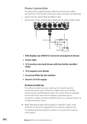
... used to control the power state of Navico modules such as SonicHub, StructureScan, and Broadband radar. The following : • power into the system (Red and Black wires) • remote turn-on for a typical small system. 20 | Wiring | HDS Gen3 Installation Manual For connection, simply combine all yellow wires on the moment the display is powered up line. The thickest of the supplied power cable...
... used to control the power state of Navico modules such as SonicHub, StructureScan, and Broadband radar. The following : • power into the system (Red and Black wires) • remote turn-on for a typical small system. 20 | Wiring | HDS Gen3 Installation Manual For connection, simply combine all yellow wires on the moment the display is powered up line. The thickest of the supplied power cable...

Installation Manual US
Page 24
... corresponding blue socket labeled 'Sonar'. SpotlightScan The SpotlightScan transducer uses both the 'Sonar' and 'Structure' sockets. Refer to the transducer cable is designed for more information. Once inserted, turn locking collar to the socket labelled 'Structure'. contact your Lowrance dealer for use of this manual, or embossed labeling on the unit for further information. 22 | Wiring | HDS Gen3 Installation Manual Navico transducers fitted with the 7 pin...
... corresponding blue socket labeled 'Sonar'. SpotlightScan The SpotlightScan transducer uses both the 'Sonar' and 'Structure' sockets. Refer to the transducer cable is designed for more information. Once inserted, turn locking collar to the socket labelled 'Structure'. contact your Lowrance dealer for use of this manual, or embossed labeling on the unit for further information. 22 | Wiring | HDS Gen3 Installation Manual Navico transducers fitted with the 7 pin...
Installation Manual US
Page 26
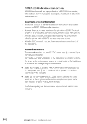
... 78m (256 ft). • A NMEA 2000 network, using standard cabling, has a maximum cable length of 100 m (328 ft), between any location in the backbone for smaller systems. For larger systems, introduce power at each end of 6 m (20 ft). The following diagram demonstrates a typical small NMEA 2000 network: 24 | Wiring | HDS Gen3 Installation Manual Essential network information • A network consists of...
... 78m (256 ft). • A NMEA 2000 network, using standard cabling, has a maximum cable length of 100 m (328 ft), between any location in the backbone for smaller systems. For larger systems, introduce power at each end of 6 m (20 ft). The following diagram demonstrates a typical small NMEA 2000 network: 24 | Wiring | HDS Gen3 Installation Manual Essential network information • A network consists of...
Installation Manual US
Page 43
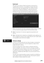
... well as the HDS Gen3. Software setup | HDS Gen3 Installation Manual | 41 CZone setup In order to communicate with the CZone modules connected to take a laptop computer aboard the vessel. Refer to the Operator manual on setting up data overlays or a gauge on the Instruments page using the Fluid Level device data. Note: A maximum of 5 tanks are supported using the CZone Configuration...
... well as the HDS Gen3. Software setup | HDS Gen3 Installation Manual | 41 CZone setup In order to communicate with the CZone modules connected to take a laptop computer aboard the vessel. Refer to the Operator manual on setting up data overlays or a gauge on the Instruments page using the Fluid Level device data. Note: A maximum of 5 tanks are supported using the CZone Configuration...

Installation Manual US
Page 56
... www.lowrance.com NMEA 2000 Part number ...GPS AND HEADING RC42 RATE COMPASS Ethernet cables Part Number 000-0127-51 000-0127-29 000-0127-30 000-0127-37 Description ETHERNET CABLE YELLOW 5 PIN 2M (6.5FT) ETHERNET CABLE YELLOW 5 PIN 4.5M (15FT) ETHERNET CABLE YELLOW 5 PIN 7.7M (25FT) ETHERNET CABLE...HDS GEN2/3 VIDEO ADAPTER CABLE HDS-7 GEN3 TOUCH BEZEL AND CARD DOOR HDS-9 GEN3 TOUCH BEZEL AND CARD DOOR HDS-12 GEN3 TOUCH BEZEL AND CARD DOOR HDS-7 GEN3 TOUCH SUNCOVER HDS-9 GEN3 TOUCH SUNCOVER HDS-12 GEN3 TOUCH SUNCOVER HDS-7 GEN2/3 TOUCH GIMBAL BRACKET Accessories | HDS Gen3 Installation Manual
... www.lowrance.com NMEA 2000 Part number ...GPS AND HEADING RC42 RATE COMPASS Ethernet cables Part Number 000-0127-51 000-0127-29 000-0127-30 000-0127-37 Description ETHERNET CABLE YELLOW 5 PIN 2M (6.5FT) ETHERNET CABLE YELLOW 5 PIN 4.5M (15FT) ETHERNET CABLE YELLOW 5 PIN 7.7M (25FT) ETHERNET CABLE...HDS GEN2/3 VIDEO ADAPTER CABLE HDS-7 GEN3 TOUCH BEZEL AND CARD DOOR HDS-9 GEN3 TOUCH BEZEL AND CARD DOOR HDS-12 GEN3 TOUCH BEZEL AND CARD DOOR HDS-7 GEN3 TOUCH SUNCOVER HDS-9 GEN3 TOUCH SUNCOVER HDS-12 GEN3 TOUCH SUNCOVER HDS-7 GEN2/3 TOUCH GIMBAL BRACKET Accessories | HDS Gen3 Installation Manual
Quick Start Guide US
Page 6
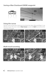
Multi-touch zooming 6 | HDS Gen3 Touch | QuickStart Guide Drag your finger in any direction to activate the cursor. Saving a Man Overboard (MOB) waypoint Using the cursor Tap the screen or press the Cursor keys to pan the screen. Select Clear Cursor or press the Exit key to remove the cursor from the page.
Multi-touch zooming 6 | HDS Gen3 Touch | QuickStart Guide Drag your finger in any direction to activate the cursor. Saving a Man Overboard (MOB) waypoint Using the cursor Tap the screen or press the Cursor keys to pan the screen. Select Clear Cursor or press the Exit key to remove the cursor from the page.


